Universal Gas Detector Series Operations Manual - RC Systems
←
→
Page content transcription
If your browser does not render page correctly, please read the page content below
Universal Gas Detector Series
   Operations Manual
              8621 Hwy 6
          Hitchcock, TX 77563
             409-986-9800        UM-1067
         www.rcsystemsco.com    Revision A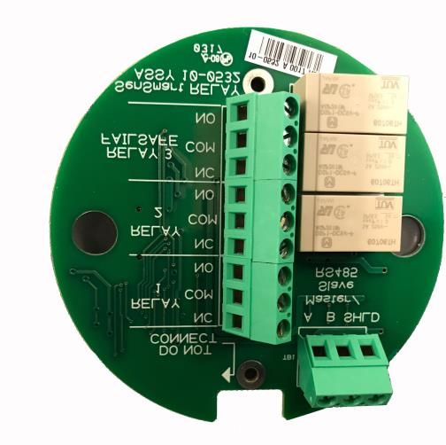
Table of Contents
Table of Figures ................................................................................................................................. I

Chapter 1            Safety Information .......................................................................................................1

   1.1       Safety Information – Read Before Installation and Applying Power ............................................................1

   1.2       Contacting RC Systems Inc. ..........................................................................................................................1

Chapter 2            General Description .....................................................................................................2

Chapter 3            Installation Instructions ...............................................................................................3

   3.1       Selecting a Location .....................................................................................................................................3

   3.2       Mounting the Enclosure ...............................................................................................................................4

   3.3       Power and Analog Outputs Wiring...............................................................................................................4

      3.3.1          SenSmart 4000 ...................................................................................................................... 5

      3.3.2          SenSmart 5000 and SenSmart 8000X ................................................................................... 5

   3.4       Option Board Wiring ....................................................................................................................................6

      3.4.1          SenSmart 5000 RS 485 Option Board.................................................................................... 6

      3.4.2          SenSmart 5000 Relay Option ................................................................................................ 7

   3.5       Remote Sensor Installation ..........................................................................................................................8

      3.5.1          SenSmart 5000 Remote Sensor ............................................................................................ 8

      3.5.2          SenSmart 8000X Remote Sensor .......................................................................................... 8

   3.6       Sensor Installation and Replacement .........................................................................................................10

   3.7       Smart Sensors .............................................................................................................................................10

Chapter 4            General Operating Instructions .................................................................................. 11

   4.1       Introduction ................................................................................................................................................11

   4.2       General Setup for SenSmart 4000 and SenSmart 5000 ..............................................................................11

 UM-1067
 Revision A                                                                                                                                                                    I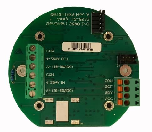
4.3         Wireless Network Setup for SenSmart 8000 and SenSmart 8000X ............................................................12

   4.4         Normal Operation ......................................................................................................................................12

   4.5         Fault Condition ...........................................................................................................................................12

   4.6         Alarm Conditions ........................................................................................................................................13

       4.6.1           SenSmart 4000 .................................................................................................................... 13

       4.6.2           SenSmart 5000 and SenSmart 8000X ................................................................................. 13

Chapter 5              Calibration Procedure ................................................................................................ 14

   5.1         Preparation ................................................................................................................................................14

   5.2         Routine Calibration Procedure ...................................................................................................................16

   5.3         Bump Test Procedure .................................................................................................................................17

Chapter 6              Maintenance Procedure ............................................................................................. 18

   6.1         Regular Maintenance .................................................................................................................................18

   6.2         Sensor Replacement ...................................................................................................................................18

Appendix 1             Gas Detector Specifications ........................................................................................ 19

Appendix 2             Sensor Specifications ................................................................................................. 22

Appendix 3             Modbus Table and Operations ................................................................................... 24

   System Registers......................................................................................................................................................25

   Relay Registers ........................................................................................................................................................27

   Sensor Registers ......................................................................................................................................................29

   Channel Registers ....................................................................................................................................................30

Appendix 4             Menu Navigation ....................................................................................................... 33

Output Settings................................................................................................................................ 34

Appendix 5             Antenna Selection ...................................................................................................... 40

 UM-1067
 Revision A                                                                                                                                                                     II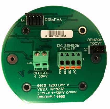
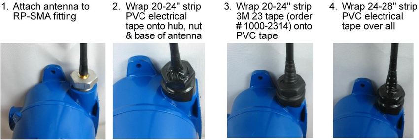
Antenna Transmission Range ..................................................................................................................................40

  Antenna Selection and Location ..............................................................................................................................40

  Water-proofing Antenna Connections ....................................................................................................................41

  Dipole and Collinear Antennas ................................................................................................................................41

  Yagi Antennas..........................................................................................................................................................42

  Mounting Near other Antennas ..............................................................................................................................42

  Coax Cables .............................................................................................................................................................42

  Surge Protection and Grounding .............................................................................................................................43

  Antenna Grounding .................................................................................................................................................43

  Connections to other Equipment .............................................................................................................................44

Appendix 6            Ordering Information ................................................................................................. 45

Appendix 7            Frequently Asked Questions ....................................................................................... 46

Appendix 8            Channel States ........................................................................................................... 48

Appendix 9            Drawings ................................................................................................................... 49

  Drawings .................................................................................................................................................................49

 UM-1067
 Revision A                                                                                                                                                                      III
Table of Figures
Figure 1 Mounting Dimensions ..................................................................................................................... 4

Figure 2 SenSmart 4000 ................................................................................................................................ 5

Figure 3 SenSmart 5000 Wiring .................................................................................................................... 5

Figure 4 SenSmart 5000 Modbus Option Wiring .......................................................................................... 6

Figure 5 SenSmart 5000 Relay Option Wiring............................................................................................... 7

Figure 6 Remote Sensor Option .................................................................................................................... 8

Figure 7 Wireless Remote Sensor Option ..................................................................................................... 9

Figure 8 Stainless Steel Sensor Head .......................................................................................................... 10

Figure 9 Universal Gas Detector Data Display Screens ............................................................................... 12

Figure 10 SenSmart 5000 Fault Screen ....................................................................................................... 13

Figure 11 SenSmart 5000 and SenSmart 8000X Alarm Screens ................................................................. 13

Figure 12 Calibration Diagram .................................................................................................................... 15

Figure 13 Calibration Menu Flowchart ....................................................................................................... 16

Figure 14 Water-proofing Antenna Connections........................................................................................ 41

Figure 15 10-0517 CPU Board ..................................................................................................................... 50

Figure 16 10-0533 I/O Board....................................................................................................................... 50

Figure 17 10-0531 Modbus Board .............................................................................................................. 51

Figure 18 10-0529 2.4 GHz Board ............................................................................................................... 51

Figure 19 10-0530 900 MHz Board ............................................................................................................. 52

Figure 20 10-0532 Modbus/Relay Board .................................................................................................... 52

Figure 21 10-0535 4-20mA Output ............................................................................................................. 53

 UM-1067
 Revision A                                                                                                                                                 I
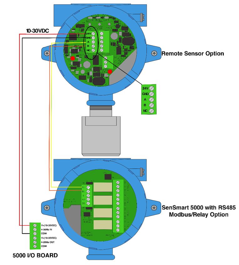
Figure 22 10-0534 Battery Board ................................................................................................................ 53

 UM-1067
 Revision A                                                                                                                                           II
Chapter 1 Safety Information
1.1 Safety Information – Read Before Installation and Applying Power
The following symbols are used in this manual to alert the user of important instrument operating
issues:
This symbol is intended to alert the user to the presence of important operating and
! maintenance (servicing) instructions.
This symbol is intended to alert the user to the presence of dangerous voltage within the
instrument enclosure that may be sufficient magnitude to constitute a risk of electric
shock.
WARNINGS:
WARNING- EXPLOSION HAZARD - DO NOT REPLACE FUSE UNLESS POWER HAS BEEN SWITCHED
OFF OR THE AREA IS KNOWN TO BE NON-HAZARDOUS.
WARNING- EXPLOSION HAZARD - DO NOT DISCONNECT EQUIPMENT UNLESS POWER HAS BEEN
SWITCHED OFF OR THE AREA IS KNOWN TO BE NON-HAZARDOUS.
Use a properly rated CERTIFIED AC power (mains) cable installed as per local or national codes
A certified AC power (mains) disconnect or circuit breaker should be mounted near the
controller and installed following applicable local and national codes. If a switch is used instead
of a circuit breaker, a properly rate CERTIFIED fuse or current limiter is required to be installed
as per local or national codes. Markings for positions of the switch or breaker should state (I)
for on and (O) for off.
Clean only with a damp cloth without solvents.
Equipment not used as prescribed within this manual may impair overall safety.
1.2 Contacting RC Systems Inc.
To contact RC Systems Inc., call, fax, email or write:
409–986-9800 FAX 409-986-9880 Email: info@rcsystemsco.com
8621 Hwy. 6 Hitchcock, TX 77563
Or visit us on the Web at www.rcsystemsco.com
UM-1067
Revision A 1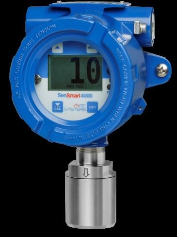
Chapter 2              General Description
The Universal Transmitter Series consists of a
common processor board connected to various
combinations of input output options. The
models are based on wireless vs wired
communications; and powering as follows:

SenSmart 4000 – Low-power, 4-20mA loop
powered gas detector for toxic and oxygen
detection. Includes a 4-20mA output.
                                                             SenSmart 4000

SenSmart 5000 – 10-30VDC powered gas
detector for toxic, oxygen, combustible, VOC and
CO2 detection. This model adds a color backlit
LCD display and has Modbus and/or 4-20mA
communications and relays available.

SenSmart 8000 – Battery powered wireless gas
detector for toxic, oxygen, combustible and CO2
detection. Available in either 900MHz or 2.4GHz             SenSmart 5000
models.

SenSmart 8000X – 10-30VDC powered wireless
gas detector for toxic, oxygen, combustible and
CO2 detection. This model adds a color backlit
LCD display.

All models use RC Systems latest Smart Sensor
technology, providing smarter gas detection
with simplified solutions.

                                                   SenSmart 8000 and 8000X

 UM-1067
 Revision A                                                                  2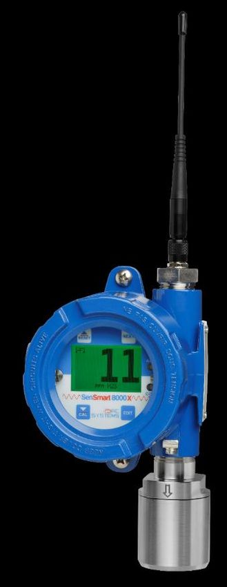
Chapter 3                Installation Instructions
3.1 Selecting a Location

Factors such as air movement, gas density in relation to air,
emission sources and environmental variables affect correct
sensor location.

Air movement by fans, prevailing winds and convection should be
carefully evaluated to determine if a leak is more likely to raise gas
levels in certain areas within the facility.

                                      Vapor density of a gas determines if it will rise or fall in air when
                                      there are no significant currents. Lighter than air gases should have
                                      the detector mounted 12 to 18 inches (30 to 45 cm) above the
                                      potential gas leak, and heavier than air gases should be this
                                      distance below the potential gas leak.

The Universal Series of gas detectors are designed for
rugged service in the field. However, sensors should always
be protected from environmental damage from water,
snow, shock, vibration and dirt.

 UM-1067
 Revision A                                                                                              3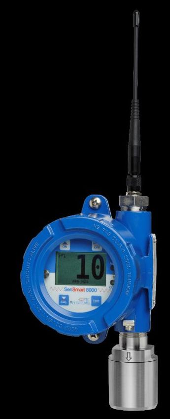
3.2 Mounting the Enclosure

              Install the detector to a wall or bracket using the predrilled mounting flanges with I.D. 0.25
              on 5-inch centers (Figure 1). If conduit is rigid and able to support the weight of the
              universal detector, the mounting bolts may be omitted.

After you have determined the appropriate location for your gas detector, it is important to securely
mount the gas detector using the predrilled mounting flanges on the enclosure. Dimensions for the
mounting holes can be found for both the aluminum and poly enclosures in Figure 3-1.

                                         Figure 1 Mounting Dimensions

3.3 Power and Analog Outputs Wiring
              WARNING: Qualified personnel should perform the installation according to applicable
              electrical codes, regulations and safety standards. Ensure correct cabling and sealing
              fitting practices are implemented. Do not aim the sensor pointing upward.

Modular design simplifies the installation of the universal gas detectors. A top display assembly is
mounted with captive thumbscrews and is easily removed to access field-wiring terminals. Option

 UM-1067
 Revision A                                                                                               4
boards mount to the back of the display assembly, and power, input and output wires mount to the
power supply board.
3.3.1 SenSmart 4000
The SenSmart 4000 is powered through a non-polar 4-20mA loop connected to TB2. Connect the +10-
30VDC/4-20mA loop wires to TB2.1 and TB2.2 on the 2-wire 4-20mA Output Board (Figure 2).
TB2. 1 - +10-30VDC/4-20mA
(non-polar)
TB2. 2 - +10-30VDC/4-20mA
(non-polar)
12
TB2
Figure 2 SenSmart 4000
3.3.2 SenSmart 5000 and SenSmart 8000X
The SenSmart 5000 and SenSmart 8000X are 10-30VDC powered and have a dedicated 4-20mA output
terminal. Connect the 10-30VDC Positive wire to terminal TB2.1. Connect the 10-30VDC Negative
(Common) wire to terminal TB2.3. Connect the 4-20mA signal wire to terminal TB2.5 on the I/O Board
(not necessary for SenSmart 8000X wireless communication) (Figure 3).
TB2. 1 - 10 to 30VDC
Positive (+)
1
2
3
TB2. 3 - 10 to 30VDC 4
Common (-) 5
6
TB2. 5 - 4-20mA Output
1
Figure 3 SenSmart 5000 Wiring
UM-1067
Revision A 53.4 Option Board Wiring
3.4.1 SenSmart 5000 RS 485 Option Board
The RS 485 Option (Figure 4) adds a single Modbus master port and a single Modbus slave port.
For the Modbus master port, connect your Modbus communication wires to terminals TB1.A and TB1.B,
and connect your shield wire to TB1.SHLD.
For the Modbus slave port, connect your Modbus communication wires to terminals TB2.A and TB2.B,
and connect your shield wire to TB2.SHLD. Note that there are two sets of terminals labeled TB2.A and
TB2. B. This allows you to connect multiple SenSmart 5000 gas detectors in series. Each SenSmart 5000
represents an RS-485 slave and must have a unique Remote ID address (slave address). It is also
important to note that wiring should be daisy chained as opposed to a star pattern for reliable
operation. RC Systems recommends using shielded twisted pair cable such as Belden 3106A.
A
B
S
TB1 – RS485 Modbus Master Port
TB1
TB2 – RS485 Modbus Slave Port
A
B
TB2
S
A
B
Figure 4 SenSmart 5000 Modbus Option Wiring
UM-1067
Revision A 63.4.2 SenSmart 5000 Relay Option
The SenSmart 5000 Relay option (Figure 5) includes three programmable relays and a single
programmable RS 485 Modbus master or slave port. The relay labeled “FAILSAFE” is set up as a failsafe
Fault relay by default but can be configured as a programmable relay in the Relay Settings menu. It is
possible to use only the relays, only Modbus or both.
The relay terminals are labeled NO (Normally Open), NC (Normally Closed) or C (Common, or pole).
These designators correspond to the shelf, or de-energized, state of the relays. When a relay is in
Failsafe mode, it is energized when the alarm condition is not met, and therefore its action is reverse of
the designators.
For the RS-485 Modbus master/slave port, connect your Modbus communication wires to terminals
TB1.A and TB1.B, and connect your shield wire to TB1.SHLD.
ABS
RLY 1
TB1
TB1 – RS485 Modbus Master/
Slave Port
RLY 2
TB2
TB2 – Relay Terminals
FLT
Figure 5 SenSmart 5000 Relay Option Wiring
UM-1067
Revision A 73.5 Remote Sensor Installation
3.5.1 SenSmart 5000 Remote Sensor
Use of the Remote Sensor Option Board requires the SenSmart 5000 to be equipped with a RS 485
Option or Relay Option Board. The Remote Sensor Option Board communicates to the SenSmart 5000 by
utilizing one of the RS-485 communication ports located on the option board.
Connect 24VDC and ground wires to the 24V and GND terminals on TB1 or TB2 of the Remote Sensor
Option Board to supply the necessary 24V. Connect the A and B terminals of TB1 or TB2 of the Remote
Sensor Option Board to the A and B Master Port terminals of the Relay/RS-485 Option Board.
Figure 6 Remote Sensor Option
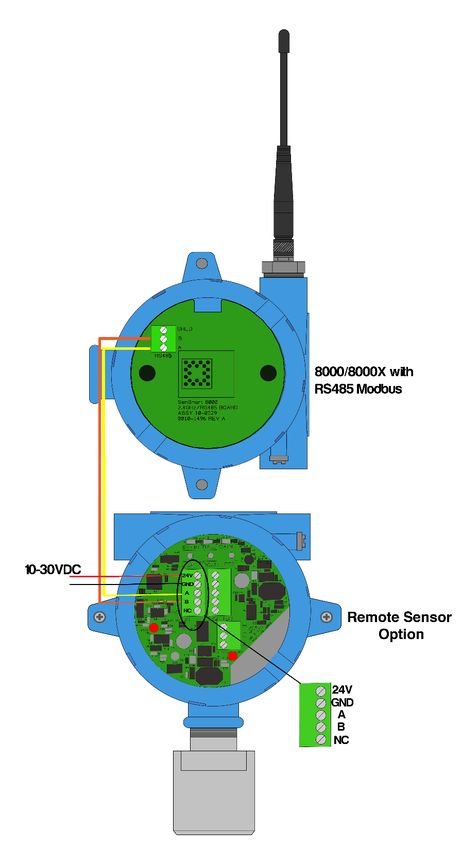
3.5.2 SenSmart 8000X Remote Sensor
The Remote Sensor Option Board communicates with the SenSmart 8000X via the Modbus master port
located on the SenSmart 8000X’s radio board.
UM-1067
Revision A 8Connect 24VDC and ground wires to the 24V and GND terminals on TB1 or TB2 of the Remote Sensor
Option Board to supply the necessary 24V. Connect the A and B terminals of TB1 or TB2 of the Remote
Sensor Option Board to the A and B Master Port terminals of the radio board of the SenSmart 8000X.
Figure 7 Wireless Remote Sensor Option
UM-1067
Revision A 93.6 Sensor Installation and Replacement
The Universal Gas Detector series of monitors utilize RC Systems’ Gen II Smart Sensors. These sensors
come factory installed and provide our highest level of performance with increased accuracy and signal
to noise ratio. The 8-conductor Smart Sensor interface connector attaches to the J1 connector on the
base board, and the detector detects the type of sensor automatically. This makes it easier than ever to
switch from any of our electrochemical Smart Sensors to any of our bridge (infrared, catalytic bead and
PID) Smart Sensors without having to reconfigure wiring.
3.7 Smart Sensors
WARNING: Prior to performing sensor replacement ensure the area has been declassified.
To install a new sensor, simply remove the sensor head cap, remove the old sensor assembly and align
the alignment arrows on the new sensor assembly with the sensor head body and press the sensor
assembly toward the sensor head body until it has fully seated in the connector. The sensor board
should be flush with the edge of the sensor head body when fully seated. Reinstall the sensor head cap
and follow the on-screen prompts to upload the sensor settings into the gas detector.
Important: Sensor assembly must be fully inserted into the sensor head body when
! tightening the sensor head cap. Failure to do so could result in damage to the sensor and/or
the sensor head body.
Figure 8 Stainless Steel Sensor Head
UM-1067
Revision A 10Chapter 4 General Operating Instructions
4.1 Introduction
Swiping a magnetic wand past the Edit key, from any of the Data Display screens, displays the Main
Menu. The Up and Down keys maneuver the selection bar up and down and Edit selects the highlighted
item to enter the sub-menus. All items with a sub-menu are indicated by a right facing arrow at the end
of the line. To edit menu item values, swipe the Edit key, and use the Up and Down keys to edit the
value. Once the desired value is entered, swipe the Edit key again to save the value. Swipe the Next key
to reverse out of a sub-menu.
Important: Some values require a Technician Sequence to be entered to change their
values. This is to prevent the operator from inadvertently changing the values. When
! prompted to “Enter technician sequence:” simply swipe the Up key four times to unlock the
value for editing.
4.2 General Setup for SenSmart 4000 and SenSmart 5000
After ensuring proper installation perform the following steps:
1. Apply power to the gas detector
2. Verify the detector has begun startup.
Note: Once the detector is on the data screen, you may notice high or low values out of the full-scale
range. These values should quickly return to the zero-gas value if no gas is present. No false alarms
should be indicated at this time as the zero-gas value will be transmitted by the detector during the
user-defined warmup delay period (up to 5 minutes).
3. Using the magnetic interface, navigate the menus to ensure:
a) Alarm levels for Alarm 1, 2 and 3 are set to the desired value
Note: SenSmart 5000 series gas detectors have optional relays, which should also be set up at this time.
When no relays are installed, alarms are indicated only by the display color and/or alarm LEDs.
b) Time and date are set correctly
c) Engineering units are set to the desired value
d) Calibration span gas value is set to the value of the calibration gas that will be used to
perform initial calibration
e) Calibration marker is set to the desired value (this is the value the output will be held at
during calibration and the calibration purge delay)
4. After sensor has stabilized, perform routine sensor calibration in accordance with Chapter 5.
UM-1067
Revision A 114.3 Wireless Network Setup for SenSmart 8000 and SenSmart 8000X
The Universal Gas Detector series utilizes R.C. Systems’ WaveNet wireless technology to make setup
simplified with three easy steps.
1. Power on the SenSmart 8000/8000X (for the SenSmart 8000 hold a magnet over the Up key, for
the SenSmart 8000X apply 10-30VDC to the power terminals).
Note: Once the detector is on the data screen, you may notice high or low values out of the full-scale
range. These values should quickly return to the zero-gas value if no gas is present. No false alarms
should be indicated at this time as the zero-gas value will be transmitted by the detector during the
user-defined warmup delay period (up to 5 minutes).
2. Using the magnetic interface, navigate the menus to:
a. Ensure the Network ID matches the Network ID of the controller.
b. Set the RTU number to the desired number.
3. Verify proper operation by ensuring readings on gas detector and controller match.
4.4 Normal Operation
During normal operation the sensor data is displayed on one of three data display screens as shown
below. To cycle through the data display screens, use a magnet and swipe the Next key until the desired
screen is reached.
Figure 9 Universal Gas Detector Data Display Screens
4.5 Fault Condition
The Fault alarm is used to indicate a condition when there is a failure from the sensor or an out of range
state has been reached. It is recommended to set the fault alarm level to -10% of the span value. For
example, if an H2S sensor is installed with a span value of 100, the fault should be set at -10, or if an
oxygen sensor is installed with a span value of 25, the fault setting should be -2.5.
If relays are installed, the Fault relay is always Failsafe. This is necessary for the relay to de-energize in
the event there is a loss of power, so that a Fault will be indicated.
If relays are not installed, a Fault condition will only be indicated by the display color changing to red
and/or the red Fault LED flashing.
UM-1067
Revision A 12Figure 10 SenSmart 5000 Fault Screen
4.6 Alarm Conditions
4.6.1 SenSmart 4000
Alarm levels are user configured. When an alarm condition is met the alarm condition will be indicated
by the alarm LED flashing.
4.6.2 SenSmart 5000 and SenSmart 8000X
The SenSmart 5000 and SenSmart 8000X allow the user to select the color associated with a certain
alarm level. Options include yellow, orange, red, blue and purple. Alarm 1 is always set to yellow, and
the Fault alarm is always set to Red.
Figure 11 SenSmart 5000 and SenSmart 8000X Alarm Screens
When an alarm level is reached, the display will change to the user defined color and the alarm level will
flash on the display. If Latching is turned on, the alarm will stay enabled until the user acknowledges the
alarm, even if the alarm condition has cleared.
UM-1067
Revision A 13Chapter 5 Calibration Procedure
5.1 Preparation
Calibration is the most important function for ensuring correct operation of the Universal Series of gas
detectors. The CAL MODE is designed to make calibration quick, easy and error free, and a successful
Zero and Span calibration requires only four keystrokes. The 4-20mA output transmits 3mA during the
calibration, and 4mA during calibration purge to prevent alarms. After 5 minutes of inactivity the gas
detector will exit calibration mode automatically.
RC Systems recommends performing calibrations
Immediately prior to placing a gas detector in service
Any time a new sensor is installed
Every six months for routine calibrations (more often if sensor is known to have been
exposed to gas for extended periods of time)
Periodic bump tests are recommended if detector has potentially been exposed to
incompatible gases to ensure correct operation
Follow these calibration guidelines to ensure proper operation of your RC Systems, Inc. gas
detector:
Calibration accuracy is only as good as the calibration gas accuracy. RC Systems
recommends calibration gases with National Institute of Standards and Technology (NIST)
traceable accuracy to increase the validity of the calibration.
Do not use gas cylinders beyond their expiration date.
Calibrate a new sensor before it is put in use.
Allow the sensor to stabilize before starting calibration.
Calibrate on a regular schedule. RC Systems recommends once every 6 months, depending
on use and sensor exposure to poisons and contaminants.
Calibrate only in a clean atmosphere, free of background gas.
UM-1067
Revision A 14Figure 12 Calibration Diagram
Prior to beginning your calibration make sure you have the following items:
1. A cylinder of calibration gas with concentration equal to the SPAN GAS VALUE setting (RC
Systems typically recommends choosing a value at 50% of full scale.)
2. A cylinder of Zero Air (unless you are confident there is no target gas potentially present in
the area)
3. A flow regulator, a fixed flow of 0.5LPM is recommended for most applications, but some
instances may require a 1.0LPM fixed flow regulator.
4. A Calibration Cup or Calibration Adaptor
5. Sufficient length of flexible tubing to connect the regulator to the calibration adaptor
UM-1067
Revision A 155.2 Routine Calibration Procedure
Use the following step-by-step procedure to perform Zero and Span calibrations (Figure 1-2 may be used
for reference to the Menus.):
Note: The first three steps must be performed before the timer in the bottom right
! corner expires, 15 seconds, otherwise the SenSmart 6000 will exit back to the Data
Display Screen.
Cal Confirm Apply: 0 Apply: 50
Are you sure you E.Units E.Units
want to enter -25 E.Units -25 E.Units
calibration mode? -25 Raw Value -25 Raw Value
[Edit] = Set Zero [Edit] = Set Zero
[Edit] Yes, [Next] No [Next] = Cal Span [Next] = Cal Span
Figure 13 Calibration Menu Flowchart
1. Enter Calibration mode from any of the Data Display Screens by swiping the Down/Cal key.
2. Swipe the Edit key to enter Cal Mode.
3. Apply a clean Zero Gas (Figure 9), using the Calibration Cup or be sure there is no
background target gas in the monitored area. After the reading is stable, swipe the Edit key
to set the Zero Calibration. To skip the Zero calibration, and go to the Span calibration,
swipe the Next key. Once a message that the Zero calibration was completed successfully
has been displayed, proceed to the next step.
4. Apply the correct, as indicated, span gas (Figure 9). After the reading is stable, swipe the Edit
key to set the Span Calibration. To skip the Span Calibration, swipe the Next key. When a
message that the Span Calibration was completed successfully is displayed, the gas detector
will exit back to the Data Display Screen.
5. Remove the calibration gas. Once the Cal Purge Delay has expired, normal alarm and relay
functionality will be restored.
Calibration history records are logged and may be viewed in the Sensor Information.
UM-1067
Revision A 165.3 Bump Test Procedure
Note: A bump test, when performed correctly, is meant to check both sensor and
! alarm functionality. This results in expected alarms, and proper precautions should be
taken.
Also known as a functionality test, a bump test is not meant to test the accuracy of the detector, and no
calibration settings are changed during the test.
To perform a bump test, briefly expose the sensor to a gas of known concentration (above the Low
Alarm set point), and check to ensure the display reading increases to a value within tolerance of the
concentration applied and check for alarm actuation. If the sensor does not perform as expected, RC
Systems recommends performing a routine calibration and/or replacing the sensor. If the alarm does
not perform as expected check the detector’s alarm settings.
UM-1067
Revision A 17Chapter 6 Maintenance Procedure
6.1 Regular Maintenance
RC Systems recommends performing calibrations at regular intervals to ensure proper functionality of
the Universal Gas Detector. During routine calibration, RC Systems recommends a visual inspection of
sensor head, enclosure and conduit entries to check for cleanliness and physical integrity. Cleaning the
detector is recommended when necessary but be aware that some cleaning compounds may be
detected by an operational detector depending on the sensor type. So, proper precautions should be
taken.
RC Systems recommends calibrations:
Immediately prior to placing a gas detector in service
Any time a new sensor is installed
Every six months for routine calibrations (more often if sensor is known to have been
exposed to gas for extended periods of time)
Periodic bump tests are recommended if detector has potentially been exposed to
incompatible gases to ensure correct operation
6.2 Sensor Replacement
When a sensor has reached its end of life, it is necessary to replace the sensor. For sensor replacement
instructions, refer to Chapter 3.7.
UM-1067
Revision A 18Appendix 1 Gas Detector Specifications
Figure 14 SenSmart 4000 and SenSmart 5000 Specifications Table
UM-1067
Revision A 19Figure 15 SenSmart 8000 and SenSmart 8000X Specifications Table UM-1067 Revision A 20
Appendix 2                 Sensor Specifications
                                     Relateive Gas
   Target gas         Formula                            TWA              IDLH          Min Span             Max Span
                                        Density

  Acetaldehyde         C2H4O             1.5            200ppm        2000ppm (Ca)       30ppm               1500ppm
    Acetylene          C2H2              0.91              --          asphyxiant           --              0-100% LEL
    Ammonia             NH3              0.6            50ppm           300ppm           25ppm               1000ppm
    Ammonia             NH3              0.6            50ppm           300ppm          1250ppm              5000ppm
     Arsine            AsH3              2.69           0.5ppm           3ppm               --                0.5ppm
     Arsine            AsH3              2.69           0.5ppm           3ppm               --                 1ppm
    Benzene            C6H6             2.6961           1ppm           500ppm            3ppm                25ppm
     Butane            C3H8              1.55        1000ppm (pel)      2100ppm             --              0-100% LEL
 Carbon Dioxide        CO2               1.53          5000ppm         40000ppm             --              0-100%vol
 Carbon Dioxide        CO2               2.33          0.1ppm C          5ppm               --                5%/vol
 Carbon Dioxide         CO2              1.53          5000ppm         40000ppm             --                5%/vol
 Carbon Dioxide         CO2              1.53          5000ppm         40000ppm             --               1.5%/vol
Carbon Monoxide         CO               0.97           50ppm           1200ppm          40ppm               5000ppm
    Chlorine            Cl2              2.47           1ppm C           10ppm            5ppm                20ppm
Chlorine Dioxide       ClO2              2.33          0.1ppm C          5ppm             2ppm                 6ppm
  Combustible       Hydrocarbons        varies             --          asphyxiant           --               100%LEL
     Ethane            C2H6              1.07              --          asphyxiant           --              0-100% LEL
    Ethanol            C2H6O             1.6           1000ppm          3300ppm             --              0-100% LEL
    Ethylene           C2H4              0.98           200ppm         asphyxiant           --              0-100% LEL
  Ethyl Alcohol        C2H6O             1.59          1000ppm          3300ppm          40ppm               3300ppm
 Ethylene Oxide        C2H4O             1.49
Relative Humidity (non-
TYPE T50 T90 TEMP °F Application Notes A1 A2 A3
condensing)
PID --Appendix 3 Modbus Table and Operations The Universal Gas Detector series may be equipped with two optional (10-0388 Relay/RS-485 Modbus Option Board) RS-485 boards where the 10-0388 Relay board can be set up as master or slave, and the RS-485 Modbus Option board can be set up as master and slave (base 1). The Modbus slave ports allow function code 3 (write coil), as well as function code 6, and 16 (write holding registers). These function codes can be used to write configuration parameters to the Universal Gas Detectors. Writing parameters that span multiple register (such as 32bit floating points) requires function code 16. All registers must be written at once. The following table describes the Universal Gas Detector series Modbus slave database. Any portion of this data may be read by a Modbus master device such as a PC, PLC or DCS. Since the Modbus port is RS- 485, multiple Universal Gas Detectors may be multi-dropped onto the same cable. UM-1067 Revision A 24
System Registers
Input Registers
                                        Function   Function
Tag                Address   Type       Code to    Code to    Size   Notes
                                        Read       Write
                                                                     0- OK
                                                                     1- Alarm 1
                                                                     2- Alarm2
                                                                     3- Alarm3
                                                                     4- Fault
                                                                     5- Warmup
                                                                     6- Inhibited
                                                                     7- Zero Calibration
                                                                     8- Calibration Span
                                                                     9- Calibration Purge
                             Unsigned                                10- Calibration Mode
Packed Status      31000                   4         N/A       1
                             Integer                                 11- Diagnostics Mode
                                                                     12- Value Error (Calibration needed or
                                                                     Channel State Over range)
                                                                     13- Sensor Error
                                                                     (Channel State Corrupted,
                                                                     Channel State Over range,
                                                                     Channel State Mismatch,
                                                                     Channel State No Sensor,
                                                                     Channel State Sensor Error,
                                                                     Channel State Comm Error,
                                                                     Channel state Scaling Error)
                                                                     12-bit value;
                             Unsigned
Analog Output      31001                   4         N/A       1     800 = 4mA;
                             Integer
                                                                     4000 = 20mA
                                                                     16-bit signed integer 1 to 100
Sensor Life        31009     Integer       4         N/A       1
                                                                     1 indicates Calibration Required
                             32-Bit
                                                                     16-bit integer 1 to 4095
Temperature        31011     Floating      4         N/A       2
                                                                     scaled for - 55°C to +125°C
                             Point
                             32-Bit
4-20mA(mA)         31210     Floating      4         N/A       2     32-bit floating point
                             Point
                             32-Bit
Bridge Supply(V)   31220     Floating      4         N/A       2     32-bit floating point
                             Point
                             32-Bit
Bridge Out(V)      31224     Floating      4         N/A       2     32-bit floating point
                             Point
                             Unsigned
Version            32002                   4         N/A       1     Factory use only
                             Integer

UM-1067
Revision A                                                                                              25
Boot Date 32006 Date 4 N/A 2 Last Power up date
Boot Time 32009 Time 4 N/A 2 Last Power up Time
Holding
Registers
Command
Alarm Reset 40001 write 1 to 3 6 1 Write to acknowledge alarm
activate
Command
Set Unity 40002 write 1 to 3 6/16 1
activate
Command
Start Inhibit 40003 write 1 to 3 6/16 1
activate
Command
Stop Inhibit 40004 write 1 to 3 6/16 1
activate
Packed
Name 40010 Character 3 6/16 1 16-character ASCII text
String
Date 40020 Date 3 6/16 2 Current Data
Time 40023 Time 3 6/16 2 Current Time
Warmup Time 40027 Integer 3 6/16 1 Warm up delay (minutes)
Cal Purge Time 40028 Integer 3 6/16 1 Cal purge delay (minutes)
0-Clear
Block Negative 40029 Selection 3 6/16 1 1-Triggered
1 prohibits display of values < 0
0-Modbus slave
Comm Mode 40030 Selection 3 6/16 1 1-Remote sensor
MODBUS serial port #1
0 -9600
1 - 19200
Baud Rate 40031 Selection 3 6/16 1 2 - 38400
3 - 57600
4 - 115200
0- None
Parity 40032 Selection 3 6/16 1 1- Even
2-Odd
Remote ID 40033 Integer 3 6/16 1
0-ABCD
1-CDAB
Byte Order 40036 Selection 3 6/16 1
2-BADC
3-DCBA
Comm 1 LED 0-No
40038 Selection 3 6/16 1
Enable 1-Yes
Comm 1 Term 0-No
40039 Selection 3 6/16 1
Resistor 1-Yes
UM-1067
Revision A 26Comm 2 LED 0-No
40048 Selection 3 6/16 1
Enable 1-Yes
Comm 2 Term 0-No
40049 Selection 3 6/16 1
Resistor 1-Yes
Table 1 System Registers
Relay Registers
Input Registers
Function Function
Tag Address Type Code to Read Code to Write Size Notes
0-Clear
Standard Relay 1 State 32020 Selection 4 N/A 1
1-Triggered
0-Clear
Standard Relay 2 State 32021 Selection 4 N/A 1
1-Triggered
0-Clear
Standard Relay 3 State 32022 Selection 4 N/A 1
1-Triggered
0-No
Warmup 32025 Selection 4 N/A 1
1-Yes
0-No
Standard Relay 1 Flashing 32026 Selection 4 N/A 1
1-Yes
0-No
Standard Relay 2 Flashing 32027 Selection 4 N/A 1
1-Yes
0-No
Standard Relay 3 Flashing 32028 Selection 4 N/A 1
1-Yes
Holding Registers
0-Alarm 1
1-Alarm 2
3-Alarm 3
3-Fault
Relay 1 Source 40106 Selection 3 6/16 1
4-Cal Mode
5-Cal Zero
6-Cal Span
7-Disabled
0-No
Relay 1 Acknowledge 40107 Selection 3 6/16 1
1-Yes
0-No
Relay 1 Failsafe 40108 Selection 3 6/16 1
1-Yes
Relay 1 Refresh Time 40109 Integer 3 6/16 1
UM-1067
Revision A 270-Alarm 1
1-Alarm 2
3-Alarm 3
3-Fault
Relay 2 Source 40116 Selection 3 6/16 1
4-Cal Mode
5-Cal Zero
6-Cal Span
7-Disabled
0-No
Relay 2 Acknowledge 40117 Selection 3 6/16 1
1-Yes
0-No
Relay 2 Failsafe 40118 Selection 3 6/16 1
1-Yes
Relay 2 Refresh Time 40119 Integer 3 6/16 1
0-Alarm 1
1-Alarm 2
3-Alarm 3
3-Fault
Relay 3 Source 40126 Selection 3 6/16 1
4-Cal Mode
5-Cal Zero
6-Cal Span
7-Disabled
0-No
Relay 3 Acknowledge 40127 Selection 3 6/16 1
1-Yes
0-No
Relay 3 Failsafe 40128 Selection 3 6/16 1
1-Yes
Relay 3 Refresh Time 40129 Integer 3 6/16 1
Table 2 Relay Registers
UM-1067
Revision A 28Sensor Registers
Input Registers
Function Function
Code to Code to
Tag Address Type Read Write Size Notes
0-No
Send Sensor Life 40153 Selection 3 6/16 1
1-Yes
Packed 16 ASCII characters (2 per
Contact Info String 40160 3 6/16 1
Character String register)
0-Unlocked
Security 40182 Selection 3 6/16 1
1-Locked
Packed 16 ASCII characters (2 per
Measurement Name 40401 3 6/16 1
Character String register)
Packed 10 ASCII characters (2 per
E. Units 40423 3 6/16 1
Character String register)
PGA Gain 40433 Integer 3 6/16 1 Contact Factory
32-Bit Modbus 32-bit IEEE 754
Zero Setpoint 42001 3 6/16 2
Floating Point Floating Pt
32-Bit Modbus 32-bit IEEE 754
Span Setpoint 42003 3 6/16 2
Floating Point Floating Pt
32-Bit Modbus 32-bit IEEE 754
Zero Value 42005 3 6/16 2
Floating Point Floating Pt
32-Bit Modbus 32-bit IEEE 754
Span Value 42007 3 6/16 2
Floating Point Floating Pt
32-Bit Modbus 32-bit IEEE 754
Fault Value 42009 3 6/16 2
Floating Point Floating Pt
32-Bit Modbus 32-bit IEEE 754
Alarm 1 Setpoint 42011 3 6/16 2
Floating Point Floating Pt
32-Bit Modbus 32-bit IEEE 754
Alarm 2 Setpoint 42013 3 6/16 2
Floating Point Floating Pt
32-Bit Modbus 32-bit IEEE 754
Alarm 3 Setpoint 42015 3 6/16 2
Floating Point Floating Pt
32-Bit Modbus 32-bit IEEE 754
Calibration Gain 42017 3 6/16 2
Floating Point Floating Pt
32-Bit Modbus 32-bit IEEE 754
Calibration Offset 42019 3 6/16 2
Floating Point Floating Pt
Table 3 Sensor Registers
UM-1067
Revision A 29Channel Registers
Input Registers
Function Function
Tag Address Type Code to Code to Size Notes
Read Write
0-No
Alarm 1 Status 33017 Selection 4 N/A 1
1-Yes
0-No
Alarm 1 Flashing 33018 Selection 4 N/A 1
1-Yes
0-No
Alarm Status 33019 Selection 4 N/A 1
1-Yes
0-No
Alarm Flashing 33020 Selection 4 N/A 1
1-Yes
0-No
Alarm 3 Status 33021 Selection 4 N/A 1
1-Yes
0-No
Alarm 3 Flashing 33022 Selection 4 N/A 1
1-Yes
0-No
Fault Status 33023 Selection 4 N/A 1
1-Yes
Comm Error 33024 Selection 4 N/A 1 True if comm error
Config Error 33025 Selection 4 N/A 1 True if config error
I/O Error 33026 Selection 4 N/A 1 True if input/output error
Calibration Flag 33027 Selection 4 N/A 1 True if calibration in progress
Error Flashing 33030 Selection 4 N/A 1 True if channel error
32-Bit
Value 33065 4 N/A 2
Floating Point
Holding Registers
Function Function
Tag Address Type Code to Code to Size Notes
Read Write
0-No
Alarm 1 Latch 43001 Selection 3 6/16 1
1-Yes
0-High
Alarm 1 Trip 43002 Selection 3 6/16 1
1-Low
Alarm 1 On Delay 43003 Integer 3 6/16 1 Activation delay in seconds
Alarm 1 Off Delay 43004 Integer 3 6/16 1 Deactivation delay in minutes
Alarm 1 Deadband% 43005 Integer 3 6/16 1 Percent of scale
0-No
Alarm 2 Latch 43011 Selection 3 6/16 1
1-Yes
UM-1067
Revision A 300-High
Alarm 2 Trip 43012 Selection 3 6/16 1
1-Low
Alarm 2 On Delay 43013 Integer 3 6/16 1 Activation delay in seconds
Alarm 2 Off Delay 43014 Integer 3 6/16 1 Deactivation delay in minutes
Alarm 2 Deadband% 43015 Integer 3 6/16 1 Percent of scale
0-Red
Alarm 2 Color 43016 Selection 3 6/16 1 1- Orange
2-Blue
0-No
Alarm 3 Latch 43021 Selection 3 6/16 1
1-Yes
0-High
Alarm 3 Trip 43022 Selection 3 6/16 1
1-Low
Alarm 3 On Delay 43023 Integer 3 6/16 1 Activation delay in seconds
Alarm 3 Off Delay 43024 Integer 3 6/16 1 Deactivation delay in minutes
Alarm 3 Deadband% 43025 Integer 3 6/16 1 Percent of scale
0-Red
Alarm 3 Color 43026 Selection 3 6/16 1 1- Orange
2-Blue
0-No
Alarm 3 Enabled 43027 Selection 3 6/16 1
1-Yes
0-Sensor
Data From 43031 Selection 3 6/16 1 1-Remote Sensor
2-4-20mA
Unsigned
Min Raw 43032 3 6/16 1 Binary (800)
Integer
Unsigned
Max Raw 43033 3 6/16 1 Binary (4000)
Integer
Remote ID 43034 Integer 3 6/16 1 Binary
Remote ID 43042 Integer 3 1
Decimal Points 43079 Selection 3 6/16 1 Number of decimal points
Modbus 32-bit IEEE 754
Deadband(%) 43081 Integer 3 16 1
Floating Pt
Filter Count 43090 Integer 3 6/16 1 Binary ;0 to 60
Polarity 43092 Selection 3 6/16 1 Binary
32-Bit Modbus 32-bit IEEE 754
Bridge Voltage 43093 3 16 2
Floating Point Floating Pt
Balance 43095 Integer 3 6/16 1 Binary
0-No
Heater Enabled 43096 Selection 3 6/16 1
1-Yes
32-Bit Modbus 32-bit IEEE 754
Heater Setpoint 43097 3 16 2
Floating Point Floating Pt
UM-1067
Revision A 31Temperature
Temp Comp -40C 43099 3 16 4 32-bit FP Gain ;32-bit FP Offset
Comp
Temperature
Temp Comp -30C 43103 3 16 4 32-bit FP Gain ;32-bit FP Offset
Comp
Temperature
Temp Comp -20C 43107 3 16 4 32-bit FP Gain ;32-bit FP Offset
Comp
Temperature
Temp Comp -10C 43111 3 16 4 32-bit FP Gain ;32-bit FP Offset
Comp
Temperature
Temp Comp 0C 43115 3 16 4 32-bit FP Gain ;32-bit FP Offset
Comp
Temperature
Temp Comp 10C 43119 3 16 4 32-bit FP Gain ;32-bit FP Offset
Comp
Temperature
Temp Comp 20C 43123 3 16 4 32-bit FP Gain ;32-bit FP Offset
Comp
Temperature
Temp Comp 30C 43127 3 16 4 32-bit FP Gain ;32-bit FP Offset
Comp
Temperature
Temp Comp 40C 43131 3 16 4 32-bit FP Gain ;32-bit FP Offset
Comp
Temperature
Temp Comp 50C 43135 3 16 4 32-bit FP Gain ;32-bit FP Offset
Comp
Temperature
Temp Comp 60C 43139 3 16 4 32-bit FP Gain ;32-bit FP Offset
Comp
0-None, 1-EC, 2-Bridge, 3-Low
Sensor Type 43143 Selection 3 6/16 1
Power IR
32-Bit Modbus 32-bit IEEE 754
Cal mA Setting 43145 3 16 2
Floating Point Floating Pt
Table 4 Channel Registers
UM-1067
Revision A 32Appendix 4 Menu Navigation
Main Menu
Output Settings >
Input Settings >
Comm Settings >
Security
Event Log
System
Technician
>
>
>
>
Main Menus
Alarm Outputs
Output Settings
Analog Output > The Alarm Outputs Menu is accessed via the Main Menu, and is
Relay 1 >
Relay 2 >
used to configure the mapping of the three programmable
Relay 3 >
Inhibit >
relays to the alarm setpoints, and relay configuration items
such as Acknowledge, Failsafe and Override.
Input Settings
Alarm 1 > Input Settings
Alarm 2 >
Alarm 3 > The Input Settings Menu provides access to user configurable
Fault Alarm >
Data From > input parameters. This includes Alarm settings for all three
Configure >
Calibration
Temp Comp
>
>
alarms, access to the data from menus (where you can adjust
sensor settings for various types of sensors including sensor
Comm Setting voltage for bridge type sensors), input configuration settings
Mode Modbus Slave
Remote Sensor > including tag name, engineering units and inCal mA, calibration
Radio Setup >
Modbus Slave > span value, and the Temperature compensation table.
Com Settings
Security
The Com Settings Menu provides access to the settings for the
Security Unlocked Modbus configuration, when installed.
Code to Lock
****
Contact Info
Security
Allows the user to enter a passcode to restrict access to some
settings
Event Log
View Events >
Clear Events >
Event Log
The Event Log allows the user to view a list of recent events
logged in the transmitter, and to clear the log. Events are
logged in a first in first out manner.
System
Version v1.07
Name
Date
SenSmart
09/05/2018
System
Time 14:04:37 User adjustable items which effect the entire gas detector, and
Set Contrast >
are not specific to either channel.
Technician Technician
Analog >
Relays > The Technician Menu provides access to a variety of useful
Inputs >
Diagnostics > troubleshooting screens to view ADC reading, Discrete I/O,
Current input, Sensor life and access to the diagnostics mode
for testing analog outputs, relay function and LED operation.
Help
The Help Menu provides a QR Code link to this manual
UM-1067
Revision A 33Output Settings
Output Settings
Output Settings Menus
Analog Output >
Relay 1 > Analog Outputs
Relay 2 >
Relay 3 > o Fault mA
Inhibit >
Allows the user to configure the mA output when the
detector is in the Fault condition. This is useful to indicate a
fault condition on the connected control device.
Analog Outputs
o Cal mA
Fault mA 1 Allows the user to configure the mA output when the
Cal mA 3
detector is in Cal Mode. This is useful to indicate a
calibration condition on the connected control device.
Relay 1, 2, 3
o Source
The Source setting can be set to Alarm 1, Alarm 2, Alarm 3,
Relay 1
Source Alarm 1 Fault, Cal Mode, Cal Zero, Cal Span or Disabled. This setting
Failsafe No
Acknowledge No determines which condition must be met in order for the
Refresh(m) No relay to actuate.
State Clear
o Failsafe
When set to Yes, Failsafe means the relay de-energizes
during alarm and energizes with no alarm. This is useful for
Relay 2
Source Alarm 2
signaling an alarm on a loss of power. The dedicated Fault
Failsafe No relay is always Failsafe.
Acknowledge No
Refresh(m) No o Acknowledge
State Clear
When set to Yes, Acknowledge means the UP/RESET key will
set the relay to its normal state even if the alarm condition
still exists. This can be useful for silencing audible devices
Relay 3 driven from the relay.
Source Fault o Refresh
State Clear
When enabled, this feature refreshes the relay for
acknowledged alarms if the indicated time elapses and the
alarm condition still exists
o State
Inhibit Indicates the current state of the relay
InhibitTime(m) 15
Start Inhibit > Inhibit
Stop Inhibit > o Fault mA
Timer(s) 0
The inhibit feature allows the user to inhibit outputs during a
designated time period. Once the timer has been started all
outputs will be blocked until the time has expired.
o Start Inhibit
Starts the inhibit timer
o Stop Inhibit
Stops the inhibit timer
o Timer (s)
Indicates the time remaining on the inhibit timer in seconds
UM-1067
Revision A 34Input Settings
Alarm 1 >
Alarm 2 >
Alarm 3 >
Fault Alarm
Data From
Configure
>
>
>
Input Settings Menus
Setpoint (Alarm 1, 2, 3 and Fault)
Input Settings
Calibration > Setpoint enters the engineering unit value where the alarm will
Temp Comp >
trip. It may be negative, and trip when monitored values fall out
of range in this direction.
Latching (Alarm 1, 2, 3)
Setting Latching to YES causes the alarm to remain active even
after the condition is gone, and to reset only when the
Alarm 1 UP/RESET key is swiped from a data display.
Setpoint 20
Latching No
Trip High
On Delay(sec) 0 Trip (Alarm 1, 2, 3)
Off Delay(min) 0
Deadband % 1 Set Trip to HIGH to have the alarm trip when the value goes
above the setpoint. Set to LOW to trip when the value falls
below the setpoint.
Alarm 2 On Delay (sec) (Alarm 1, 2, 3)
Setpoint 40
Latching No On Delay allows entering a maximum 10 second delay before
Trip High
On Delay(sec) 0 this alarm becomes active. This is useful for preventing
Off Delay(min) 0
Deadband % 1
spurious alarms by brief spikes beyond the alarm setpoint.
Alarm 2 Off Delay (min) (Alarm 1, 2, 3)
Color Red Off Delay allows entering a maximum 120-minute delay before
clearing an alarm after the alarm condition is gone. This is
useful for continuing an alarm function, such as operation of an
exhaust fan, for a period of time after the alarm condition
clears.
Deadband % (Alarm 1, 2, 3)
Alarm 3
Enabled Yes Deadband allows forcing low values to continue to read zero.
Setpoint 60
Latching No This is useful when there are small amounts of background
Trip High
On Delay(sec) 0 gases that cause fluctuating readouts above zero. The highest
Off Delay(min) 0
amount of Deadband allowed is 5%.
Alarm 3
Deadband % 1
Color (Alarm 2, 3)
Color Red Selecting Color changes the color associated with the particular
alarm. Options are Red, Blue, Purple and Orange.
Enabled (Alarm 3)
Set to YES to enable Alarm 3 and NO to disable.
Fault Alarm
Setpoint 0
UM-1067
Revision A 35Data From
Source Sensor
Remote Sensor No
Min Raw 800
Max Raw 4000
Remote ID 1
Alias 31001 Input Settings Menus (cont’d)
Data From (certain menu items only show up depending on the input type)
Data From o Source determines the type of sensor installed in the detector. E.g. bridge,
Interface COM1 electrochemical, etc.
Filter(second) 5
Byte Order ABCD o Remote Sensor set to Yes indicates that the sensor is installed remotely with Remote
Polarity Negative
Heater Enabled No sensor option.
Heat (degC) 25 o Min and Max Raw set the range of the input to the A/D converter. Normally set to
800/4000. Useful when the sensor’s output doesn’t provide a full range signal.
Data From o Remote ID is where the Modbus slave’s ID number is entered
Set Voltage >
Set Balance > o Alias is the register number which defines the location of the variable representing the
Set PGA > input value of the Modbus data received through the communication ports
Marker >
o Interface assigns which communication port the Modbus slave is connected to and the
detector will get its data from
o Filter (second) sets the number of seconds over which samples are averaged
o Byte Order determines WORD and BYTE alignment of data at the remote Modbus
Configure
Tag Measurement Name transmitter when sending this 4-byte IEEE floating point values
E.Units E .Units o Polarity determines the polarity of the sensor
Zero 0
Span 100 o Heater Enabled determines if the sensor heater is turned on or off
Decimal Points 0
Block Negative Yes o Heat (degC) is the thermostat setting of the sensor
o Set Voltage set’s the voltage being supplied to bridge type sensors
Configure
o Set Balance adjusts the balance of a catalytic bead sensor and must only be adjusted
Deadband (%) 1 with ZERO gas on the sensor.
Warmup(m) 1
Cal Purge(m) 1 o Set PGA is the adjustment that matches the input signal range to the detectors input
signal conditioning circuits.
o Marker used to detect special modes of operation from analog inputs, which some
monitors use to indicate special modes of operation, such as calibration mode
Configure
Calibration o Tag is a 16-character ASCII field typically used to describe the monitored point by user
ZeroSetpoint 0 tag number or other familiar terminology.
SpanSetpoint 50
Cal Gain 1 o E. Units or engineering units may have up to 10 ASCII characters, and is usually factory
Gain Offset 0 configured based on sensor type.
Set Unity >
Calibrate > o Zero defines the reading to be displayed when the output is 4mA (0%)
o Span defines the reading to be displayed when 20mA (100%) is the output.
o Decimal Points sets the resolution of the displayed reading, and may best to zero, one
Temp Comp or two.
-40C g1.000:o+0.000
-30C g1.000:o+0.000
o Block Negative blocks negative values from being display (Displays 0).
-20C g1.000:o+0.000 o Deadband (%) allows forcing low values to continue to read zero. This is useful when
-10C g1.000:o+0.000
0C g1.000:o+0.000 there are small amounts of background gases that cause fluctuating readouts above
10C g1.000:o+0.000
zero. The highest amount of Deadband allowed is 5%. Note: Deadband affects all
outputs as well as the local reading.
Temp Comp o Warmup (m) defines the time allotted for sensor warmup. During this time output s will
20C g1.000:o+0.000
30C g1.000:o+0.000 be held at a zero value and relays will stay in their normal state.
40C g1.000:o+0.000 o Cal Purge (m) determines the amount of time the transmitter will stay in calibration
50C g1.000:o+0.000
60C g1.000:o+0.000 mode after calibration is complete as the sensor returns to normal state.
Calibration
o Zero Setpoint is set to the zero value.
o Span Setpoint is set to the calibration gas value, typically 50% of full scale.
o Cal Gain reflects the change made when calibrating.
o Gain Offset reflects the change made when calibrating.
o Gain Unity is to reset the Gain and Offset back to default (1 and 0 respectively)
o Calibrate is used to calibrate sensors.
Temp Comp allows the user to adjust the gain and offset that is applied to sensors to
compensate for temperature drift. Factory supplied sensors are preprogrammed with
these values which are automatically uploaded from the Smart Sensor.
UM-1067
Revision A 36You can also read