5000 Series Audio/Video System - Installation & Service Manual - Hamilton Security
←
→
Page content transcription
If your browser does not render page correctly, please read the page content below
A Wholly Owned Subsidiary of Gunnebo AB

     5000 Series Audio/Video System
                  Installation & Service Manual

08-315 (2/6/17)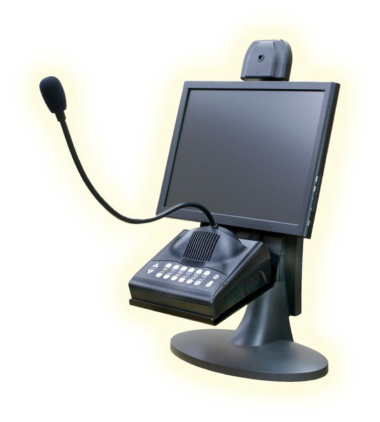
Table of Contents

    Description.....................................................................................................3
    System Configuration.....................................................................................3
    Cable Considerations......................................................................................4
    Matrix Installation..........................................................................................4
    Matrix / System Wiring Diagram...................................................................5
    Cat 5 Lane Speaker/Driver Kit Installation....................................................6
    Wireless Headset Installation.........................................................................7
    E10052 Wireless Expansion Adapter.............................................................8
    5512 Remote Handset Installation.................................................................8
    5012 Remote Handset..................................................................................10
    5570 / 5571 Remote Customer Audio Consoles..........................................11
    5572 / 5573 Remote Customer “In Wall” Audio Units................................12
    5550 Teller Video Unit Installation..............................................................14
    5650 Teller Video Unit Installation..............................................................16
    5517 Remote Video Unit Installation...........................................................18
    5617 Remote Video Unit Installation...........................................................21
    Video Power Control Wiring for 5517 / 5617..............................................23
    5550/5517 LCD Menu Adjustments............................................................24
    E0465-3WD-LP License Plate Camera Installation.....................................25
    E0465-3WD-LPXLR License Plate Camera Installation.............................26
    Audio Matrix Switch Settings......................................................................27
    Video Matrix Switch Settings......................................................................28
    Adjusting the Audio System........................................................................29
    Mixing 5501 Series Consoles With Different Firmware Revisions.............30
    Changing the Call Tone Type & Volume....................................................31
    Colored Lane Stickers for 5501 Series Consoles.........................................31
    System Operating Instructions.....................................................................32
    Echo Canceller & Background Noise Cancellation.....................................33
    Troubleshooting Tips...................................................................................34
    Using E10278 Vehicle Detectors With 5000 Series Audio.........................36
    Frequently Asked Questions........................................................................37
    Hamilton Audio/Video Part Numbers..........................................................43
    Part Number Photos.....................................................................................46

2                                                                                                                       08-315 (2/6/17)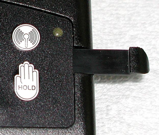
Description
The 5000 Series system consists of components that allow 2-way audio and video communications between teller consoles
and customer units in banks, pharmacies and other service environments. The audio is full duplex which allow both parties to
hear and speak at the same time and includes echo cancellation and background noise cancellation circuitry. The video
circuitry is analog (composite video).

System Configuration
To configure a new system using current components:
1) Determine the maximum number of teller consoles and customer lanes required and select audio/video matrixes with an
    adequate number of ports. Note that 2-lane audio matrixes are shipped with power supplies but others require that the
    power supply be ordered separately. Video matrixes and audio consoles receive their power from the audio matrix.
         Audio Matrix
              5003..............................Supports 1 teller & 2 customers - includes power supply (see 5501-1KIT below)
              5004..............................Supports 2 tellers & 2 customers - includes power supply
              5002-4...........................Supports 3 tellers & 4 customers - requires power supply E10171
              5002-8...........................Supports 6 tellers & 8 customers - requires power supply E10171
              5002-12.........................Supports 6 tellers & 12 customers - requires power supply E10171
         Video Matrix
              5005-4...........................Supports 3 tellers & 4 customers
              5005-8...........................Supports 6 tellers & 8 customers
              5005-12.........................Supports 6 tellers & 12 customers
         Audio/Video Matrix
              5006..................Supports 2 tellers & 2 customers - includes power supply
2) Select the required number of teller audio consoles with the required number of customer lane buttons.
              5501-2...........................2 lanes
              5501-4...........................4 lanes
              5501-8...........................8 lanes
              5501-12.........................12 lanes
              5501-1KIT....................This is a kit number that includes a 5501-2 audio console with a 5003 matrix.
3) Select the proper number of lane microphones and speakers if these do not already exist. Note that there are a wide
    variety of electret microphones on the market and all have different characteristics. Using an existing microphone may
    not provide optimum results. Also the system is designed for a 4 ohm lane speaker. A comparable 8 ohm speaker could
    be used but the volume would be reduced. Factory installed microphones and speakers in Hamilton Air units are correct
    for this system.
              E0604............................Lane microphone with 48” leads
              B4956...........................Lane speaker, 4 ohm, 3”
4) If video is being used, select the proper number of teller and customer video units if cameras and monitors do not already
    exist. Existing video units must use composite video.
              5550..............................Teller Video Unit (10.4” LCD & camera) - includes stand & power supply
              5650..............................Teller Video Unit (15” LCD & camera) - includes stand & power supply
              5517..............................Remote Video Unit (10.4” LCD & camera) - includes mounting arm & power supply
              5517-SUN.....................Remote Video Unit (10.4” Sun View LCD & camera) includes mounting arm & power
                                                supply
              XLR-2WTV-MOUNT..Required to mount the 5517 or 5517-SUN to an HA1000-XLR pneumatic unit
              5617A-S........................Remote Video Unit (15” LCD & camera) - includes side mounting arm & power
                                                supply - unit has a built-in speaker & mic - Not compatible with HA1000-XLR
              5617A-P........................Remote Video Unit (15” LCD & camera) - includes mounting post & power supply -
                                                unit has a built-in speaker & mic
              5617A-SUN-S...............Remote Video Unit (15” Sun View LCD & camera) includes side mounting arm &
                                                power supply - unit has a built-in speaker & mic - Not compatible with HA1000-XLR
              5617A-SUN-P...............Remote Video Unit (15” Sun View LCD & camera) includes mounting post & power
                                                supply - unit has a built-in speaker & mic
              E10036..........................Video Power Control Cable - Recommended for any 5517 or 5617 used with a
                                                Hamilton pneumatic unit that has an E0873-C I/O control board so a teller can turn the
                                                customer LCD on/off
              E0885............................Video Power Control Kit - Recommended for pneumatic units that cannot use the
                                                E10036 power control cable - only one kit required per system

08-315 (2/6/17)                                                                                                                     3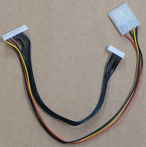
Cable Considerations
Be sure to use the proper cable for connecting the matrix to the customer lanes. For audio it is HIGHLY
RECOMMENDED to use Hamilton cable (E0680) for distances up to approximately 180 feet. This
cable contains a 16AWG twisted pair for the speaker, a 20AWG twisted pair for the call button and a
20AWG twisted, shielded pair for the microphone. For distances over 180 feet it may be necessary to
use a heavier gauge of wire for the speaker to prevent excessive loss due to the wire resistance.

 If you don’t use E0680 cable, make sure the microphone pair is individually shielded with it’s own
drain wire. DO NOT use cable with an overall shield. DO NOT use cable with individually shielded
pairs that have a common drain wire. If your cable has individually shielded pairs, with each pair having
it’s own drain wire, only connect the drain wire for the microphone pair. See the drawing and second
bullet point on the next page for microphone shield connections.

Another option for audio is to use Category 5 cable (5E & 6 are also acceptable) for distances up to
1000 feet. Using this type of cable requires the Cat 5 Lane Speaker Driver Kit (E0958-KIT). 110VAC
must also be available at the lane. This kit is also ideal for extending standard audio cable up to 1000
feet. See the section “Cat 5 Lane Speaker/Driver Kit Installation” for more information. Volumes must
be kept low when using this kit with Cat 5 cable. The use of standard audio cable is recommended
instead where possible.

For video applications use 75 ohm coax cable designed for CCTV applications. Belden 1426A is a very
good cable to use for reference. It has a solid copper center conductor and a copper braid providing 95%
shielding. Another option for video is to use twisted pair cable with video baluns. The specifications of
the video balun manufacturer must be followed as to the category of cable that is acceptable and whether
power is required.

Matrix Installation
Mount the audio (and video) matrix in an accessible but out of the way location near where the consoles
will be located. The drawing shows two mounting methods for all but the 5003 audio matrix which has a
small plastic enclosure with mounting tabs.

4                                                                                           08-315 (2/6/17)
Matrix / System Wiring Diagram
Refer to the drawing below for standard wiring connections. The drawing shows a 4-lane matrix but the
same wiring applies to all versions. Observe the following guidelines.
        The ground wire connection shown for the audio matrix is not required for the 5003 matrix.
          he drain wire (shield) for the microphone pair should not be connected at the microphone.
        However if an E0873-C I/O board is present in a Hamilton pneumatic unit the drain wire should
        connect to terminal 7 of the audio connector on that board.
        For audio-only systems the audio console(s) may be plugged into any of the console ports of the
        audio matrix. When video is used the console ports must match for a particular teller position.
        For example if the audio console is plugged into CONSOLE 1 of the audio matrix, the camera
        and monitor for that same teller must be plugged into CONSOLE 1 of the video matrix.
        The auxiliary video source, if used, must provide composite video.
        If auxiliary audio is used and the source only has a mono output, it may be plugged into either
        the L or R connector on the audio matrix. The LEVEL pot adjusts the volume of the aux audio.

                                                                                     MINIMUM Power
                                                                                         Power     Supply
                                                                                               Supply     Rating
                                                                                                      Legend

                                                                                       5003
                                                                                         5003      12VDC // 3A
                                                                                                   12VDC    1A
                                                                                       5004
                                                                                         5004      12VDC // 3A
                                                                                                   12VDC    1A
                                                                                       5006
                                                                                         5006      12VDC // 3A
                                                                                                   12VDC    1A
                                                                                       5002-4
                                                                                         5002-4    12VDC // 3A
                                                                                                   12VDC    3A
                                                                                       5002-8
                                                                                         5002-8    12VDC // 5A
                                                                                                   12VDC    5A
                                                                                       5002-12
                                                                                         5002-12   12VDC // 5A
                                                                                                   12VDC    5A

                                           Do not connect the shield at the microphone –
                                           See the 2nd bullet point above for connection
                                                     to a Hamilton I/O board

08-315 (2/6/17)                                                                                                    5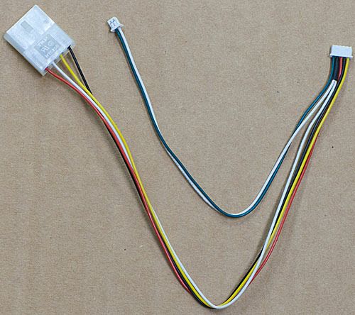
Cat 5 Lane Speaker/Driver Kit Installation
The Cat 5 Lane Speaker Driver Kit (E0958-KIT) allows for the use of Category 5 cable from the matrix
to the customer lane for distances up to 1000 feet. Cat 5e & Cat 6 may also be used. This kit is also ideal
for extending standard audio cable up to 1000 feet. Volumes must be kept low when using this kit with
Cat 5 cable. The use of standard audio cable is recommended instead where possible.

    Install the E0958 enclosure inside the customer unit in a convenient location.
    Attach the cable from the matrix to the RJ-45 connector (J3) as shown below. If standard audio
    cable is being used a short Cat 5 pigtail will be needed to splice the wires to the RJ-45 connector.
    Attach the lane speaker, microphone & call button to the 8 pin connector (J2).
    Plug the 12VDC power supply into J1 (center pin positive) and into a 110VAC outlet in the unit. * If
    12VDC is already available in the unit (1A min.) the E0958 board can be powered at the 12VDC
    terminals of connector J2. DO NOT connect power to both J1 & J2. Use one method or the other.
    Set R1 on the E0958 board to maximum volume (fully counter-clockwise) and set the speaker gain
    pot on the matrix to 8:30. Only increase the speaker gain at the matrix if necessary and then in small
    30 minute increments and retest. The E0958 board will boost the volume at the lane so keep the
    speaker pot at the matrix as low as possible. The lane microphone adjustment is made at the matrix
    as usual. (See the section “Adjusting the Audio System” later in this document.)

                                                                                         Connect to audio
                                                                                          connector on
                                                                                          Hamilton I/O
                                                                                             board

6                                                                                             08-315 (2/6/17)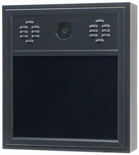
Wireless Headset Installation
The following instructions apply to Plantronics CS540, CS50 & CS55 Wireless Headsets. There are
many other wireless headsets on the market and many of these will most likely work fine but
compatibility cannot be guaranteed. Wireless headsets can be used on 5501, 5001, 4001 & 3301 Series
consoles. 3001 Series consoles typically experience volume issues with wireless headsets and are not
recommended.

Lanes cannot be selected from the headset. All lane selections must still be made at the console when
using headsets. Think of the headset as simply a different speaker & microphone. Also call tones will
sound through the console speaker, not the headset, with all consoles having a built-in wireless headset
jack. This is due to the board design and it cannot be changed.

All 5501 Series consoles and newer 5001 Series                                             5501 Series
consoles have a wireless headset adapter/jack built in                                       Console
and do not use an external adapter. Older consoles
will require a model 5014 Wireless Adapter to use
wireless headsets. If a console has the adapter built
in, do not use the 5014.
                                                                                            Wireless
                                                                                          Headset Jack
Making the Connections
  Connect the AC Power Adapter to the power jack
  on the headset base unit.                                                            Original 5014
  CS540 – Connect the provided phone cable                                            Wireless Adapter
  between the back of the headset base unit and the
  headset jack of the audio console (or the 5014                                          Wireless
  adapter if required).                                                                 Headset Jack
  CS50 / CS55 – Connect the provided short
  handset phone cable to the handset jack on the                                            Slot for
  bottom of the headset base unit. There are two                                          Ground Wire
  handset jacks; use the one with a complete picture
  of a telephone, not just a picture of a handset. Plug
  the other end of the cable into the headset jack of
                                                                                       Current 5014
  the audio console (or the 5014 adapter).                                            Wireless Adapter
  The 5014 Wireless Adapter, if required, plugs into
  the back of the audio console using the speaker /                                     Wireless
  mic phono jacks. Two types of 5014 adapters have                                    Headset Jack
  been made.
       Original 5014: Remove the (4) screws and           Mic                  Speaker
       cover from the 5014 and feed the console
       ground wire through the slot in the side of the case. Use the provided screw to attach the 5014
       case with the ground wire to the console chassis. (The wireless adapter label hides the screw hole
       in the photo.) Replace the 5014 cover. IMPORTANT: The screw must be used to secure the
       adapter to the console chassis to prevent intermittent connections.
       Current 5014: Attach the 5014 to the side of the console and flush with the rear as shown in the
       photo using the included double stick tape. Plug the labeled pigtail phono plugs into the phono
       jacks of the console. The speaker jack is closest to the adapter.

08-315 (2/6/17)                                                                                            7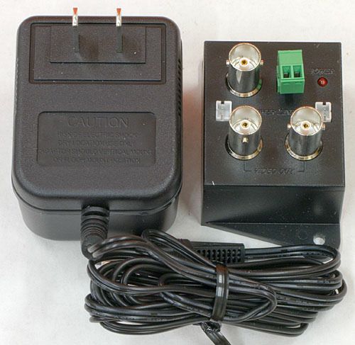
Initial Setup
    CS540 – On the bottom of the base unit set the Configuration Switch to the letter “A”. Set both the
    Listening Volume and Speaking Volume dials to the number “3”.
    CS50 / CS55 – Set the Configuration Dial on the left side of the base unit so the number “1” is
    facing to the front of the base. Set the switch on the right side of the base unit to the single tic mark.
    CS50 / CS55 – Set the Master Speak Volume located on the bottom of the base unit to the “B”
    position and the Master Listen Volume located on the back of the base to the number “2” position.
Fine Tuning the Volumes
   Make sure the speaker and microphone gain pots on the audio matrix have already been set for each
   lane while in Console Mode. Never adjust these pots while using the headset. (See the section
   “Adjusting the Audio System” later in this document.) You then switch to Wireless Mode and fine
   tune the wireless volumes to match the console volumes.
   CS540 – The rocker dial on the top end of the headset fine tunes the incoming volume. Be careful
   not to press in on this dial accidentally as this dial is also the mute switch. Changes to the volume
   dials on the bottom of the base can also be made if necessary.
   CS50 / CS55 – The up (+) and down (-) buttons on the back of the wireless base fine tune the
   outgoing volume. Each press of a button changes the volume one step. The rocker dial on the top
   end of the headset fine tunes the incoming volume. Be careful not to press in on this dial accidentally
   as this dial is also the mute switch.
Changing Between Console & Wireless Headset Use
  With 5501 series consoles – Press the Wireless button (picture of antenna) while no lane is selected.
  The yellow LED next to the button indicates wireless mode when lit.
  With newer 5001 series consoles with built-in adapter – Press the Wireless/Camera button while no
  lane is selected. The yellow LED under the microphone boom indicates wireless mode when lit.
  With older consoles which require the 5014 Wireless Adapter – Use the toggle switch on the adapter
  to switch between console and wireless mode.

E10052 Wireless Expansion Adapter                                                 Connect up to 3 wireless
                                                                                    headset base units
The E10052 Wireless Expansion Adapter is used to attach multiple
wireless headset base units to a single audio console. The adapter includes
a short cable to connect it to the audio console. Additional jacks on the
adapter are used to connect up to three headset base units.

When using the expansion adapter, if multiple headsets are active at
the same time the volumes may be slightly reduced.                            Connect directly to console or
                                                                              5014 adapter as appropriate

5512 Remote Handset Installation
The Model 5512 Handset is a replacement for the older Model 5012W (wall mount) and
5012H (side mount) handsets. It provides customer privacy and can be used with 4000
and 5000 Series audio systems. The only operational difference is removing the handset
of the 5512 from its cradle does not initiate a Teller Call like the 5012 did; a local call
button must be used for this purpose. However, the remote station speaker and
microphone are disconnected while the 5512 handset is off hook, just like the 5012.
Important Note: The handset used with the 5512 is different from the 5012 handset
and they are not directly interchangeable. Plus the current 5512 handset has a volume
roller which allows a customer to increase the volume if necessary. Also note that local
power was required for the older 5012 but is not needed with the 5512.
8                                                                                                08-315 (2/6/17)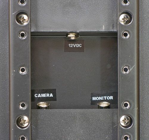
The Model 5512 can be wall mounted or mounted to the side of pneumatic tube drive-up units if desired.
Handsets that are used outdoors should be protected from direct rain.
Installation
1) Remove the 4 screws from the lid of the enclosure. This makes mounting the enclosure easy since
the entire contents are removed with the lid.
2) To wall mount the enclosure, drill mounting and cable holes in the rear of the enclosure. The upper
and lower dimples are positioned to match a single gang electrical box. Drill holes adequate for the
mounting screws that will be used. The center dimple needs to be drilled to allow for the matrix cable
and the local speaker/mic/call button cable. A minimum ¾” hole is recommended for these cables. To
side mount the box, mounting and cable holes will need to be drilled in the side of the enclosure as
required.
3) Plug the supplied paired cable into J1 on the 5512 handset             Color    Destination
board and connect the flying leads to the remote station speaker,         Black    Speaker -
call button and microphone according to the chart to the right. For
                                                                          White    Speaker +
Hamilton Air units with an I/O control board this cable would
connect to the green audio connector on the I/O board. If the 5512        Black    Call Button -
will be used alone as a remote station without a local speaker and        Green    Call Button +
microphone, a call button will still need to be wired into this cable     Black    Microphone -
or there will be no way for the customer to call for service.
                                                                          Red      Microphone +
4) Connect the cable coming from the audio matrix to P1 on the            Bare     Microphone Drain (shield)
5512 handset board. This connector can
be unplugged while making                    MATRIX
                                           AUDIO MATRIX
connections and uses the same color                                      E0680                  50125512
                                                                                                    MATRIX
                                         -SP+ -TC+ -MC+ SHLD
                                                                         Audio            P1
                                                                                           P1
code as is used at the matrix lane                                       Cable
connector.
                                                                        BLACK    SP-
5) Reinstall the 5512 lid assembly,                                     WHITE    SP+
taking care that no wires are pinched.
                                                                        BLACK    TC-
Hang up the handset.
                                                                        GREEN    TC+
6) Select the lane from an audio                                    BLACK MC-
console and adjust the audio matrix                                   RED MC+
SPK and MIC pots for that lane while                                   SHIELD
using the local speaker and mic, not the
handset, at the remote station. See the section “Adjusting the Audio System” later in this document. Do
not set the volumes any louder than necessary.
7) Lift the handset from its cradle and check for adequate volume – the local speaker and microphone
should not work while the handset is off hook. If necessary, adjust the volume pots on the 5512 handset
board to balance the handset volume to the local speaker and microphone volumes. These pots are
labeled on the board. It is recommended to adjust the speaker pot on the 5512 handset board while the
volume roller on the handset is set to minimum. This will allow a
customer to increase the volume using that roller if necessary.       SPK            P1
Important Handset Note – If the handset is ever replaced in the                  R3
future it is important to make sure that resistor R3 on the handset                        5512
board is the proper value as follows:                                                  Handset Board
                                                                         MIC
Current Handset w/Roller Volume – R3 must be 220 ohms
Original (Plain) Handset – R3 must be 5.6k ohms                                         J1

08-315 (2/6/17)                                                                                              9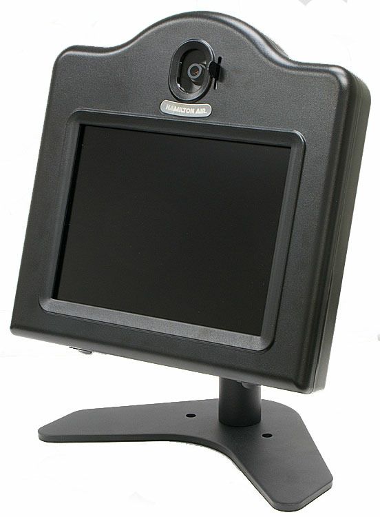
5012 Remote Handset
The 5012 Remote Handset has been replaced with the 5512 but is described here for service purposes.
With the 5012, removing the handset from its cradle initiates a Teller Call and disconnects the remote
station speaker and microphone. Important Note: The handset used with the 5012 is different from the
5512 handset. If the actual handset is swapped to the other model of unit, it will not work.

Model 5012H is mounted on the left side of pneumatic tube drive-up units, while Model 5012W is
designed for wall mounting, such as in lobby applications. These units can be used outdoors but should
be protected from rain.

       he paired pigtail cable from P2 on the 5012 board connects to Color Destination
     the remote station speaker, microphone and call button               Black Speaker -
     according to the chart to the right. The 5012 may be used alone
     without a remote station speaker, microphone and call button         White Speaker +
     by not using this pigtail cable. It can be unplugged and             Black Call Button -
     removed but should be saved for possible future needs.               Green Call Button +
       he audio cable coming from the matrix connects to P1 on the        Black Microphone -
     5012 circuit board. Unplug the connector to read the terminal
                                                                          Red Microphone +
     labeling on the board. The pinout is the same as at the matrix
     lane connector.                                                      Bare Microphone Drain (shield)
     Power is required for the 5012
     board. Either 24VAC or 12VDC                   MATRIX
                                                  AUDIO MATRIX
                                                                          E0680                50125012
     connects to the 3 pin connector (P8)       -SP+ -TC+ -MC+ SHLD
                                                                          Audio
                                                                                                   MATRIX
                                                                                        P1
                                                                                         P1
     on the 5012 board. Unplug the                                        Cable
     connector to read the pinout on the
                                                                        BLACK SP-
     board. For 24VAC use terminals 2
     & 3. For 12VDC, terminal 1 is                                       WHITE SP+

     positive and terminal 2 is negative.                               BLACK TC-
     Adjust the speaker and microphone                                  GREEN TC+
     gain pots on the matrix while using                                BLACK MC-
     the remote speaker and microphone,                                   RED MC+
     not the handset. (See the section                                      SHIELD
     “Adjusting the Audio System” later
     in this document.)
     Lift the handset from its cradle – a Teller Call tone is generated. Use the pots on the 5012 board if
     necessary to balance the handset volumes with the remote speaker and microphone volumes. XMTR
     (transmitter) is the handset mic gain and RCVR (receiver) is the handset speaker gain.
     If crosstalk from other tellers is heard at the handset look for
     resistor R11 on the 5012 handset board which is identified on
     the drawing. If a bare wire is soldered in that location then                  P2
     either replace the wire with a 6.8k ohm resistor or splice the                              R11
     resister in series with the yellow wire coming from the                          5012
     handset. Also keep volumes as low as possible.                              Handset Board
                                                                         P8           P1
                                                                                                 XMTR   RCVR

10                                                                                           08-315 (2/6/17)
5570 / 5571 Remote Customer Audio Consoles
Description
The 5570 & 5571 Remote Customer Audio Consoles consist of a speaker,
microphone and call button in a desktop type enclosure for indoor
applications. The 5570 is intended for use with standard audio cable and can
be used for cable lengths up to approximately 180 feet. The 5571 is intended
for use with Cat 5 cable and can be used for cable lengths up to 1000 feet. A
12VDC power supply is included with the 5571 and requires a 110VAC
outlet near the remote location. Volumes must be kept lower when using
the 5571. The use of the 5570 with standard audio cable is recommended 5570 / 5571
instead where possible.
In addition to free standing, the Remote Customer Audio Console can use the same mounting options as the
5501 Teller Console. Use the 5501-HWB (Horizontal Wall Bracket), the 5501-VWB (Vertical Wall Bracket)
or the B6077 (Adjustable Desktop Stand) for mounting flexibility.
Compatibility
The Remote Customer Audio Console should only be used in systems that have 5501 teller consoles or 5001
(rev. 5 or 3.1) consoles. Also feature switch #7 on the audio matrix must be set to the UP position (dynamic
echo canceller learning). Avoid using 4001, 4101 or 3001 teller consoles which will result in excessive teller
echo. 3301 teller consoles may be acceptable if the volume levels are kept low.
Installation
Make connections between the audio matrix and the rear of the 5570/5571 using the appropriate cable. Use
standard E0680 audio cable for the 5570 and Cat 5 cable (or Cat 5e or Cat 6) for the 5571. Use the included
power supply to provide 12VDC to the rear of the 5571. The power supply must be close to the 5571. Do not
significantly increase it’s cable length. For reference, the center pin of the power supply barrel connector is
positive. A raised tab is provided on the rear of the 5570 / 5571 to accept a tie-wrap for cable strain relief.
5570
5571
08-315 (2/6/17) 115572 / 5573 Remote Customer “In Wall” Audio Units
Description
The Remote Customer “In Wall” Audio Unit consists of a speaker,
microphone and call button in a recess mount double gang electrical box for
indoor applications. The model 5572 is intended for use with standard E0680
audio cable and can be used for cable lengths up to approximately 180 feet. No
remote power is required for the 5572. The model 5573 is used with Cat 5
cable and allows for cable runs up to 1000 feet. A power supply is included
with the 5573 and requires a 110VAC outlet near the remote location.
Volumes must be kept lower when using the 5573. The use of the 5572 with
standard audio cable is recommended instead where possible. 5572 / 5573
Compatibility
The Remote Customer “In Wall” Audio Unit should only be used in systems that have 5501 teller
consoles or 5001 (rev. 5 or 3.1) consoles. Also feature switch #7 on the audio matrix must be set to the
UP position (dynamic echo canceller learning). Keep the speaker and mic gain settings on the matrix to
the lowest level which will still allow adequate audio. Avoid using 4001, 4101 or 3001 teller consoles
which will result in excessive teller echo.
Installation
The photo shows a side view of the completed assembly before installation.
Remove the front plastic bezel from the unit by pressing the two plastic
tabs on the bottom with a screwdriver. Disconnect the wires from the call
button and set the bezel aside.
Next remove the four philips head screws and remove the audio assembly
from the electrical box.
Determine the mounting location and cut an opening in the wall for the
double gang electrical box.
Fish the audio cable in the wall and through one of the cable slots in the rear of
the box. The power supply cable must also be installed if using the model
5573. The power supply must be in the vicinity of the 5573 so do not extend the
power supply cable any more than necessary.
Mount the electrical box in the wall by tightening the two screws which pull
the mounting tabs against the rear of the wall.
Attach the cable to the audio assembly. Photos on the next page show the rear
of the 5572 and 5573. The drawings show the wiring of both units to the audio
matrix. Front Bezel
Removed
Note that the pot on the 5573 board must be set to the fully counter clockwise
position.
Install the audio assembly in the electrical box using the philips head screws. Make sure the rear
plastic part of the bezel is in place as shown in the photo with the front removed. Attach the leads to
the call button and then snap the front bezel into place.
12 08-315 (2/6/17)Cable
Connector
Socket
12VDC Power
Supply Socket
(center pin positive)
Leave pot set fully
counter clockwise
RJ45 Connector
for Cat 5 Cable
5572 5573
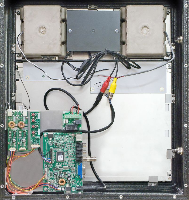
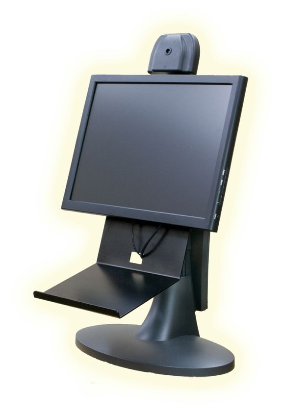
08-315 (2/6/17) 135550 Teller Video Unit Installation
The following instructions are for the current style 5550 which
contains both a camera and 10.4” LCD monitor for two-way video.
The 5550-1 is the same unit without a camera installed for one-way
video.
Installation
Separate the video head from the stand by removing 4 screws as
shown in the photo.
Using 75 ohm CCTV coax (Belden 1426A or equivalent) with
BNC connectors at each end, connect the camera and monitor at
the rear of the video head to the video matrix. Make sure to
match up the audio and video port numbers at the matrixes. For
example if the audio console is connected to Console 2 of the
audio matrix, then the video cables from that same teller
position must be connected to Console 2 of the video matrix.
Connect the supplied 12VDC power supply to the power socket
on the back of the video head. If a different power
supply must be used for some reason, it must be Screws
regulated and rated for at least 2A. The center attaching
conductor of the barrel connector is positive. Do video head
not power this unit using the power distribution to stand
board which was previously used with old B5450
units. Loosen
to adjust
With the power and video cables looped over the height
top of the stand, re-connect the video head to the
stand. A choice of holes in the video head brackets
determines the height. Additional height adjustment can be
made by loosening the knob on the rear of the stand.
Operation
Plug in the power supply and turn on the power switch on the
bottom right side of the video head.
Height adjustments can be made by loosening
the knob on the rear of the stand.
Tilt the video head by grasping the sides of the
Power &
unit. The tilt tension is not adjustable. A swivel
Video
mechanism is built into the stand. connections
Use the lever next to the camera opening to tilt on rear of
the camera up or down. Use the service/mirror video unit
switch to see the camera image on the monitor.
An alternate method is to press the HOLD
button on the audio console while no lane is
selected. Then press HOLD again to return to
normal view.
14 08-315 (2/6/17)Service Adjustments
A momentary service/mirror switch on the bottom left side of the video head disconnects the
external wiring and internally connects the camera to the
monitor for testing purposes. The service/mirror switch does
not exist on the 5550-1 since no camera is present.
he monitor has been adjusted at the factory but a menu
board allows settings to be changed if needed. The menu
board is attached to the plate on the rear of the LCD. See the
section “5550/5517 LCD Menu Adjustments” for more
information.
The camera has been adjusted at the factory but a camera
menu board (only available on later units) attached to the Service / Mirror Power
plate on the rear of the LCD screen allows camera settings to Switch Switch
be changed if needed. Use the service/mirror switch or press
the audio console hold button (with no lane selected) to connect the camera to the monitor for
viewing the menu. If focusing is required, loosen the small set screw on top of the lens and then
rotate the lens to the desired focus. Snug the set screw when finished but do not over tighten to avoid
creating a dimple in the lens threads making future fine adjustments difficult.
Camera Menu Board
SET: Used to enter the OSD menu and select menu or submenu items.
UP: Used to move up a line in a menu or submenu.
UP
DOWN: Used to move down a line in a menu or submenu.
LEFT: Used to change setting values.
RIGHT: Used to change setting values.
LEFT RIGHT Tip: Select and hold “Reset” from the “System” menu to return all settings to
DOWN SET
their default values.
08-315 (2/6/17) 155650 Teller Video Unit Installation The following instructions are for the 5650 which contains both a camera and 15” LCD monitor for two- way video. The 5650-1 is the same unit without a camera installed for one-way video. Cable Connections Remove the back cover from the stand by pulling out from the top of the cover. If the audio console shelf will be used, attach it to the bracket of the stand by using the screws already in the shelf. (The photos below show the 5650 with the shelf attached.) The power and video cables attached to the LCD, along with the audio console cable, should pass through the hole in the shelf and back over the top of the stand. Using 75 ohm CCTV coax (Belden 1426A or equivalent) with BNC connectors at each end, connect the camera and monitor pigtails to the video matrix. Make sure to match up the audio and video port numbers at the matrixes. For example if the audio console is connected to Console 2 of the audio matrix, then the video cables from that same teller position must be connected to Console 2 of the video matrix. Connect the supplied 12VDC power supply to the power socket pigtail. If a different power supply must be used for some reason, it must be regulated and rated for at least 3A. The center conductor of the barrel connector is positive. Snap the cables into the cable clamps on the back of the stand. Re-install the cover by first inserting the tabs on the bottom of the cover and then snap the top into place. Operation Plug in the power supply and press the power switch on the bottom right side of the monitor. To change the height simply lift up or press down on the monitor. Tilt the assembly by grasping the sides of the monitor. A swivel mechanism is built into the base of the stand. The camera can be tilted independently from the monitor. The black screw on the top of the camera hinge is used to adjust the tension of the tilt. To aid in adjusting the camera, press the HOLD button on the audio console while no lane is selected to view your own image. Then press HOLD again to return to normal view. 16 08-315 (2/6/17)
Service Adjustments
   The Select button on the side of the monitor is used to select the appropriate input. It should be set
   for AV. If the image on the screen displays “SV - No Signal” or “VGA - No Signal” press the select
   button to set the input back to AV.
   The monitor can be adjusted if needed using the menu buttons on the side of the monitor.
   The camera has been adjusted at the factory but a menu board allows camera settings to be changed
   if needed. The plastic camera housing must be opened to gain access to the menu board. Press the
   audio console hold button while no lane is selected to connect the camera to the monitor for viewing
   the menu. If focusing is required, loosen the small set screw on top of the lens and then rotate the
   lens to the desired focus. Snug the set screw when finished but do not over tighten to avoid creating
   a dimple in the lens threads making future fine adjustments difficult.

Monitor Menu Buttons
SELECT            Used to select the appropriate input. It should be set for AV. If the image on the screen
                  displays “SV - No Signal” or “VGA - No Signal” press the select button to set the input
                  back to AV.
MENU              Used to enter the OSD menu and select menu or submenu items.
  –               Used to move down a line in a menu or submenu and decrease setting values.
 +                Used to move up a line in a menu or submenu and decrease setting values.
                  Tip: Selecting “Reset” from the “Misc.” menu returns all settings to their factory values.
                  Note that the menu will not display if no input signal is present.

Camera Menu Board
                            SET:      Used to enter the OSD menu and select menu or submenu items.
                            UP:       Used to move up a line in a menu or submenu.
            UP
                            DOWN: Used to move down a line in a menu or submenu.
                            LEFT: Used to change setting values.
                            RIGHT: Used to change setting values.
   LEFT             RIGHT   Tip: Select and hold “Reset” from the “System” menu to return all settings to
          DOWN     SET
                            their default values.

08-315 (2/6/17)                                                                                             17
5517 Remote Video Unit Installation
The 5517 Remote Video Unit (10.4” LCD) requires 12VDC rated for a minimum of 2A to operate
properly. Power must be provided directly at the pneumatic unit to avoid a voltage drop caused by wire
resistance. Each 5517 is supplied with a power supply. With newer Hamilton pneumatic units that have
an E0873-C I/O Control Board a Video Power Control Cable (E10036) is used to allow the tellers to
control power to the LCD via the Night Lock switch. Systems that have older (or competitors)
pneumatic units will use a Video Power Control Kit (E0885) instead. See the section “Video Power
Control Wiring for 5517 / 5617” for more information.
HA1000-XLR Installation
New “XLR” units ordered with video will have the proper mounting
hardware. When video is added to an existing “XLR” unit it will be
necessary to order the XLR Mounting Arm Kit (XLR-2WTV-MOUNT)
shown in the drawing below.
Remove the front cover panel from the customer unit.
Remove the right side front stainless trim panel from the customer unit.
Remove two 10-32 x ¼ phillips pan head screws that attached the lower
right pocket to the stainless steel back panel.
Feed the video coax cables, the power supply cable and the video power
control cable from the pneumatic unit through the video mounting arm
and then attach the arm to the customer unit with four Front Right
10-32 x ¾ phillips pan head screws provided. Side Filler
Remove the screws from the back of the video head. 8-32 x 3/8
Note that not all screws are installed at the factory. The
remaining screws are in the bag of accessories.
IMPORTANT NOTE: The LCD assembly is
attached to the front of the video head enclosure Video Arm
with the current version of 5517. Separate the front Video Cover
and back of the video head enclosure being careful not Mounting
Arm 8-32 x 3/4
to pull on the cables. Unplug the video and power
cables from the LCD main board and set the front aside.
Video
Route the cables from the mounting arm through the Arm
back of the video head enclosure and attach the Cover
enclosure to the mounting arm with screws provided in Filler
the accessory bag packaged with the 5517. Two of the 10-32 x 3/4
screws are security type. A driver bit is included for the
security screws. XLR-2WTV-MOUNT
Connect the monitor coax cable to the top left BNC connector and
the camera coax cable to the top right BNC connector in the video head as labeled.
Connect the power supply cable and the video power control cable to the relay board in the video
head as shown in the section “Video Power Control Wiring for 5517 / 5617”.
Plug the power supply into a 110VAC outlet.
Install the video arm cover behind the video unit. Seal this cover to the video unit to prevent water
entry.
Install the small stainless filler piece to the back side of the video arm tube and then install the new
front right side stainless filler panel.
Install the lower front cover on the pneumatic unit.
Complete the installation by following the remaining instructions for the “Standard Arm
Installation” section beginning with adjusting the camera tilt at the bottom of the following page.
18 08-315 (2/6/17)Standard Arm Installation
The video head will be positioned to the top right of the pneumatic unit as
viewed by the customer. Use the template shipped with the 5517 to
drill holes in the top of the pneumatic unit for the video mounting
arm and cables.
Feed the video coax cables, the power supply cable and the relay
trigger wires from the Video Power Control Kit (or the E10036
Video Power Control Cable) from inside the pneumatic unit
through the top of the unit and through the video mounting arm.
Apply a small amount of silicone sealant to the bottom of the plate on the mounting arm (1) and
attach the mounting bracket to the pneumatic unit (2) with the supplied washers and nylon lock nuts.
Remove the screws from the back of the video head. Note that not all screws are installed at the
factory. The remaining screws are in the bag of accessories.
IMPORTANT NOTE: The LCD assembly is attached to the front of the video head enclosure
with the current version of 5517. Separate the front and back of the video head being careful not to
pull on the cables. Unplug the video and power cables from the LCD main board and set the front
aside.
Route the cables from the mounting arm (1) through the back of the video head enclosure (3). Apply
a small amount of silicone sealant to the plate of the mounting arm and attach the enclosure to the
mounting arm with screws (4) provided in the accessory bag packaged with the 5517. Two of the
screws are security type. A driver bit is included for the security screws.
Connect the monitor coax cable to the top left BNC connector and the camera coax cable to the top
right BNC connector in the video head as labeled.
Connect the power supply cable and the relay trigger wires (or the power control cable) to the relay
board in the video head as shown in the section “Video Power Control Wiring for 5517 / 5617”.
Slide the excess cable back through the bracket and into the pneumatic unit and then install the end
caps from the accessory bag into both ends of the mounting arm.
Plug the power supply into a 110VAC outlet.
Tilt the camera vertically in its bracket to achieve the desired viewing angle. To view the image,
temporarily connect a service monitor to the “camera” BNC connector in place of your interconnect
cable. If a service monitor is not available it will be necessary to use the 5517 monitor. In this case
reconnect the video and power cables to the LCD. DO NOT let the front of the enclosure hang
from the cables since this would likely damage the cables and/or the sockets on the LCD main
board. Place the unit in “service” mode by placing the silver service switch in the upper left of the
08-315 (2/6/17) 19video head to the rear position. This will connect the camera video directly to the monitor. Note: (1)
If a Video Power Control Cable is being used the pneumatic unit must be turned on and NOT in
night lock mode. (2) If a Video Power Control Kit is being used it must be turned on using the
lighted switch in the teller area. (3) If a Video Power Control Kit will be used but is not yet installed
it will be necessary to temporarily move the monitor power wires from the switched to the un-
switched terminals on the relay board (in parallel with the camera power wires) to test the video
unit. See the section “Video Power Control Wiring for 5517 / 5617”.
The camera has been adjusted at the factory but a menu board (not available on old units) attached
to the rear mounting plate allows camera settings such as back light compensation to be changed if
needed. See below for an explanation of the menu buttons. Use the service switch in the 5517 if
necessary to connect the camera directly to the monitor for viewing the menu. If focusing is
required, loosen the small set screw and then rotate the lens to the desired focus. Snug the set screw
when finished but do not over tighten to avoid creating a dimple in the lens threads making future
fine adjustments difficult.
The monitor has been pre-adjusted at the factory but a menu board allows settings to be changed.
The menu board is located on the rear of the LCD mounting plate for current versions. With older
versions the menu board was above the upper left of the LCD or below the LCD screen. See the
section “5550/5517 LCD Menu Adjustments” for more information. Important note for old units
that have the menu board above the upper left of the LCD – the far left button changes the type of
input that the LCD is expecting. Since it is very close to the monitor BNC connector and the service
switch it is possible to accidentally bump the button which would change the input. If a blue box
appears on the screen with the message “VGA No Signal” or “SV No Signal”, press the left button
to change the input back to AV.
Once all adjustments are satisfactory, place the unit in “normal” mode by placing the service switch
to the forward position. Make sure the video and power cables are connected to the LCD and replace
the front cover, securing with all the screws. Two of the screws are security type. A driver bit is
included for the security screws.
Camera Menu Board
SET: Used to enter the OSD menu and select menu or submenu items.
UP: Used to move up a line in a menu or submenu.
UP
DOWN: Used to move down a line in a menu or submenu.
LEFT: Used to change setting values.
RIGHT: Used to change setting values.
LEFT RIGHT Tip: Select and hold “Reset” from the “System” menu to return all settings to
DOWN SET
their default values.
20 08-315 (2/6/17)5617 Remote Video Unit Installation
The 5617 Remote Video Unit (15” LCD) is ordered either as a “post mount”
or “side mount” version. The housing types are not interchangeable. The post
mount version includes a 3” square x 36” tall post. The side mount version
includes an arm for attaching to the flat top of a pneumatic unit. The side
mount version is not compatible with the HA1000-XLR. Power must be
provided directly at the pneumatic unit to avoid a voltage drop caused by wire
resistance. Each 5617 is supplied with a 12VDC power supply (minimum
3A). With newer Hamilton pneumatic units that have an E0873-C I/O Control
Board a Video Power Control Cable (E10036) is used to allow the tellers to
control power to the LCD via the Night Lock switch. Systems that have older (or competitors)
pneumatic units will use a Video Power Control Kit (E0885) instead. See the section “Video Power
Control Wiring for 5517 / 5617” for more information.
Post Mount Version Installation
The post mount 5617 should be mounted on the island to the
right side of the pneumatic unit (as viewed by the customer)
at a slight angle. The drawing shows the suggested location as
referenced from the front right
corner of the pneumatic unit. 5.75
Existing site conditions may require
Base of Post
shifting the location
somewhat. Use the Right Front Corner
of Pneumatic Unit
1.25
base of the post as a
0.25
template for marking
the hole locations for anchors. The holes in the base are sized for 5/16” bolts.
Attach the 5617 to the post using the button head machine screws that are shipped installed in the
enclosure. Apply a small amount of silicone sealer between the post and the enclosure.
Attach the furnished 12” piece of liquid tite tubing and fittings between the pneumatic unit and the
opening at the bottom of the post. Cables will route through this tubing.
Side Mount Version Installation
The side mount version is NOT compatible with the HA1000-XLR.
Use the template shipped with the 5617 to mark and drill holes in the top of the pneumatic unit.
Attach the 5617 to the mounting arm using the button head machine screws that are shipped installed
in the enclosure. Apply a small amount of silicone sealer between the arm and the enclosure.
Attach the arm/enclosure assembly to the pneumatic unit using the included hardware. Apply a small
amount of silicone sealer between the arm and the pneumatic unit. Cables will route through the arm
into the unit.
Wiring
The photo on the next page shows the inside of a 5617 unit with the back cover removed.
Connect the monitor coax cable to the yellow RCA connector on the main board. A BNC to RCA
adapter is included for this purpose.
Connect the camera coax cable to the yellow BNC flying lead.
Connect the power supply cable and the E10036 cable (or relay trigger wires) to the relay board in
the 5617 as shown in the section “Video Power Control Wiring for 5517 / 5617”. Note that when
using the E10036 cable with a post mount 5617 the cable will not be long enough. In this case cut
the 2 pin connector off the cable and extend the cable length. Then attach the extended cable to the
trigger terminals per the drawing. The trigger terminals and J3 on the relay module are common.
08-315 (2/6/17) 21The 5617 includes a speaker and
microphone. Use the 5617 audio instead
of the speaker and microphone built into
the pneumatic unit. The speaker wires are
a black/white twisted pair and the
microphone wires are a shielded cable as
identified in the photo. Note for Hamilton
Air units that have an E0873-C I/O
Control Board: Connect the lane cable
from the audio matrix to the I/O board
Speaker & Mic
terminal strip as usual. Cut the cables Wires
from the pneumatic unit speaker and
microphone from their IDC connectors Camera Video
that plug onto the I/O board. Attach a Relay Module for
pigtail from those connectors to the Power Supply &
speaker and microphone in the 5617. Trigger Wires
Having the microphone in the 5617
attached to the I/O board will allow the Monitor Video
mute circuit to work properly.
Once the unit is powered up adjust the
camera vertically in its bracket to achieve
the desired viewing angle. If the unit is
not yet connected to the video matrix you can use a BNC patch cable to temporarily connect the
camera to the monitor. Note: (1) If a Video Power Control Cable is being used the pneumatic unit
must be turned on and NOT in night lock mode. (2) If a Video Power Control Kit is being used it
must be turned on using the lighted switch in the teller area. (3) If a Video Power Control Kit will be
used but is not yet installed it will be necessary to temporarily move the monitor power wires from
the switched to the unswitched terminals on the relay board (in parallel with the camera power
wires) to test the video unit. See the section “Video Power Control Wiring for 5517 / 5617”.
The camera has been adjusted at the factory but a menu board allows settings such as back light
compensation to be changed if needed. The 5617 camera is the same as the 5517 camera. See the
previous section for an explanation of the camera menu buttons. If focusing is required, loosen the
small set screw and then rotate the lens to the desired focus. Snug the set screw when finished but do
not over tighten to avoid creating a dimple in the lens threads making future fine adjustments
difficult.
The monitor has been adjusted at the factory but a menu board allows settings to be changed if
needed as shown below.
LCD Menu Board
1 2 3 4
1) Used to move up a line in a menu / submenu and to increase a setting value.
2) Used to enter the OSD menu, select menu / submenu items and accept changes to setting values.
3) Used to move down a line in a menu / submenu and to decrease a setting value.
4) Not used – this button may not be installed on the menu board.
Tip: Selecting “Reset” from the “Misc.” menu returns all settings to their factory values. Note that the
menu will not display if no input signal is present.
22 08-315 (2/6/17)Video Power Control Wiring for 5517 / 5617
Either of two possible methods is used to control power to the LCD inside 5517 or 5617 remote video units. For
Hamilton pneumatic units that have an E0873-C I/O control board use a Video Power Control Cable (E10036). All
other pneumatic units will require the Video Power Control Kit (E0885). Use either a Video Power Control Cable or
the Video Power Control Kit, but not both. Remember that either of these power control methods only controls the
power for the LCD. The actual power for both the camera and LCD comes from the power supply that is plugged into
the side of the relay board inside the 5517 or 5617 video head.
Refer to the drawing below which shows the wiring for both methods. Power to the LCD passes through the contacts of
the relay inside the 5517 / 5617. When the relay is energized the LCD will be ON. When the relay is relaxed the LCD
will be OFF. The camera power is not switched which allows 24/7 recording.
When using the Video Power Control Cable, each lane will require a cable. The 3 pin connector on one end of the
cable connects to J15 on the I/O Board and the 2 pin connector on the other end of the cable connects to J3 on the
Relay Board in the 5517 / 5617. The Night Lock feature for the pneumatic unit is used to control the relay.
When using the Video Power Control Kit, only one kit is required for the entire system. A wire pair connects from
any of the 12VDC outputs on the Distribution Board in the teller area to the left two “trigger” terminals on the
Relay Board in the 5517 / 5617. Wire gauge for this pair is not critical (22AWG is fine) since the relay coil only
draws 22ma. of current. Multiple wire pairs can also be connected to the same 12VDC output of the distribution
board if necessary. Use caution to make sure these wires never touch each other which will blow the fuse on the
distribution board. This sometimes happens when wires are disconnected to service or replace a video unit. Be
sure to follow the color code shown in the drawing when connecting the lighted switch to the distribution board.
08-315 (2/6/17) 235550/5517 LCD Menu Adjustments
Four types of LCD screens have been used to manufacture 5550 and 5517 video units. Refer to the
appropriate menu button arrangement below for tips on navigating the menu.
This menu board is located below the LCD screen. A dual
color LED on the right side of the board indicates power
status: green = on & red = standby.
1) Turns the monitor power on or off.
2) Not used.
3) Used to enter the OSD menu, select menu items and accept changes to setting values.
4) Used to move down a line in a submenu or to decrease a setting value.
5) Used to move up a line in a submenu or to increase a setting value.
Tip: Selecting “Factory Default” from the main menu returns all settings to their factory values.
This menu board is located at the top left of the video unit at an angle.
1 2 3 4 5
1) When not in the OSD menu: Toggles between the possible monitor inputs (AV-SV-VGA). It must
be set to AV.
When in the OSD menu: Used to move up a line in a submenu or to increase a setting value.
2) Used to enter the OSD menu, select menu items and accept changes to setting values.
3) Used to move down a line in a submenu or to decrease a setting value.
4) Not used.
5) Not used.
Tip: Selecting “Reset” from the Misc. menu returns all settings to their factory values.
A remote control (B6724) can be used to adjust this LCD without removing the cover from the unit.
This menu board is located below the LCD screen. A green power
LED is on the left side of the board.
1) Used to move up in menus and sub menus.
2) Used to move down in menus and sub menus.
3) Used to enter or exit the OSD menu and accept changes to setting values.
4) Used to enter into menus and sub menus and increase setting values.
5) Used to enter into menus and sub menus and decrease setting values.
Tip: Selecting “Reset” from the function menu returns all settings to their factory values.
This menu board is located on the plate on the back of the
LCD screen.
1) Used to move up a line in a menu / submenu and to increase a setting value.
2) Used to enter the OSD menu, select menu / submenu items and accept changes to setting values.
3) Used to move down a line in a menu / submenu and to decrease a setting value.
4) Not used – this button may not be installed on the menu board.
Tip: Selecting “Reset” from the Misc menu returns all settings to their factory values. Note that the
menu will not display if no input signal is present.
24 08-315 (2/6/17)E0465-3WD-LP License Plate Camera Installation
The following instructions are for mounting the License Plate Camera assembly on the back side of a
5517 Video Unit that uses the standard mounting arm. This camera is used for viewing the rear license
plate of a vehicle as it leaves the drive-up lane. It can be oriented to view the vehicle in the same lane as
the 5517 it is attached to or the vehicle in the previous lane simply by shifting the camera housing 90°
on it’s bracket. See the photos below.
1) Remove the cover from the License Plate Camera assembly by removing the 2 screws from the rear
of the housing. Pull the video/power cable up through the
housing so it is no longer passing through the square tube on Backside of 5517 Video Unit
the bottom.
2) Remove the plastic end cap from the outer end of the 5517
mounting bracket.
3) Insert the square tube of the License Plate Camera assembly
into the end of the 5517 bracket. While holding the
assembly in place, drill a hole through the bottom of the
5517 bracket up through the inner bracket using a #29 or
1/8” drill bit. This hole will be used later to hold the
assembly in place but for now remove the assembly.
4) A power converter is provided with the kit which converts
24VAC from the pneumatic unit to 12VDC for the new
camera. Feed the barrel connector end of the power
converter along with a video cable from inside the Drill Hole Here
pneumatic unit up through and out the end of the 5517
mounting bracket. Oriented for Viewing
5) Temporarily feed the power cable through the License Plate the Previous Lane
Camera bracket so it can be connected to the camera power
cable. Slide the assembly back into the 5517 bracket. It will
be necessary to slightly push the new video cable back into
the bracket.
6) Connect the power converter input wires to the 24VAC
terminals of the pneumatic unit. IMPORTANT: If the
“24VAC” source measures 26VAC or higher then add a
47 ohm ½ watt resistor in series with either wire to the
power converter. This will lower the voltage and prevent
possible damage to the power converter and camera.
7) Connect a service monitor to the video pigtail which is still
hanging out the top side of the License Plate Camera
assembly. Adjust the camera bracket as necessary to get the
proper view.
8) Disconnect the service monitor and power cables from the
License Plate Camera pigtail and remove the assembly.
9) Feed the video/power pigtail cable back through the License
Plate Camera bracket like it was initially and re-install the Oriented for Viewing
cover. the Same Lane as 5517
10) Attach the pigtail to the video and power cables and insert the Where Installed
License Plate Camera bracket back into the 5517 bracket.
Secure it in place with the #8 x 3/8” stainless steel screw
included with the kit.
11) Connect the remote end of the new video cable and check the new camera for proper operation.
08-315 (2/6/17) 25You can also read