SEMI-AUTOMATED 4 PUMP CONTROLLER - Software Release: S4PC v2.1 Document: TD-09-06-1036 - USC, LLC
←
→
Page content transcription
If your browser does not render page correctly, please read the page content below
SEMI-AUTOMATED
                      4 PUMP CONTROLLER
                              Operators Manual

                               Software Release: S4PC v2.1
        Document: TD-09-06-1036                                           Revision: D

2320 124th Road   Sabetha, Kansas 66534    PH: (785) 431-7900 FAX: (785) 431-7950   www.uscllc.com
                                   Revision Effective 16 FEB 2018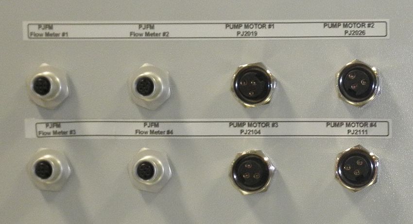
SEMI-AUTOMATED 4 PUMP CONTROLLER
Introduction
Thank you for choosing USC, LLC for your equipment needs. We appreciate your
business and will work diligently to ensure that you are satisfied with your choice.
OVERVIEW
The purpose of this manual is to provide you with the basic information needed to
install, operate and maintain the Semi-Automated 4 Pump Controller. It does not hold
USC, LLC liable for any accidents or injuries that may occur.
The technical information provided in this document is based on extensive testing
under controlled conditions at the USC research and development facility.
This information is given without guarantee as the conditions of operation and storage
of the equipment are beyond our control. Variables such as temperature, humidity,
viscosity of chemical products and changes in seed size or variety may all effect
the accuracy of application and seed coverage. Periodically check the equipment
calibration while treating and make adjustments as required. This will insure the
optimum seed coverage.
OPERATOR RESPONSIBILITIES
As the purchaser/owner/operator of this equipment and control system, you have an
obligation to install, operate, and maintain the equipment in a manner that minimizes
the exposure of people in your care to any potential hazards inherent in using this
equipment. It is critical that the owner of this equipment:
Has a clear and documented understanding of the process this machine is
being used in and of any resulting hazards or special requirements arising
from this specific application.
Allow only properly trained and instructed personnel to install, operate or
service this equipment.
Maintain a comprehensive safety program involving all who work with this
machine and other associated process equipment.
Establish clear areas of staff responsibility (e.g. operation, setup, sanitation,
maintenance, and repairs).
Provide all personnel with necessary safety equipment.
Periodically inspect the equipment to insure that the doors, covers, guards,
and safety devices are in place and functioning, that all safety instructions
and warning labels are intact and legible, and that the equipment is in good
working order.
In addition to the operating instructions, observe and enforce the applicable
legal and other binding regulations, national and local codes.
Page 2
SEMI-AUTOMATED 4 PUMP CONTROLLER
As the person with the most to gain or lose from working safely, it is important that you
work responsibly and stay alert. By following a few simple rules, you can prevent an
accident that could injure or kill you or a co-worker.
Disconnect, lockout, and tagout electrical and all other energy sources
before inspecting, cleaning, servicing, repairing, or any other activity that
would expose you to the hazards of electrical shock.
Do not operate, clean, or service this equipment until you have read and
understood the contents of this manual. If you do not understand the
information in this manual, bring it to the attention of your supervisor, or call
USC at (785) 431-7900 for assistance.
Any operator who is known or suspected to be under the influence of alcohol
or drugs should not be allowed to operate the equipment.
Understand and follow the safety practices required by your employer and
this manual.
PAY ATTENTION to what you and other personnel are doing and how these
activities may affect your safety.
Failure to follow these instructions may result in serious personal
injury or death.
RECEIVING YOUR EQUIPMENT
As soon as the equipment is received, it should be carefully inspected to make certain
that it has sustained no damage during shipment and that all items listed on the
packing list are accounted for. If there is any damage or shortages, the purchaser
must immediately notify USC, LLC. Ownership passes to purchaser when the unit
leaves the USC, LLC. premises. The purchaser is responsible for unloading and
mounting all components of the equipment.
Document the serial number of the machine for future reference. The serialization
label is located on the in the upper right hand corner of the control panel.
Serial
Number
SERIAL NUMBER:__________________________________
Page 3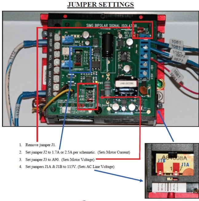
SEMI-AUTOMATED 4 PUMP CONTROLLER

    Table of Contents
Section     Contents                                                                              Page #

Section A   Safety Instructions ..................................................................... 5

Section B   Installation ................................................................................ 14
            Placement & Inspection.......................................................... 15
            Setting DC Pump Motors........................................................ 16
            DC Pump Board Settings ....................................................... 19

Section C   Mechanical Operation .............................................................. 21
            Control Panel Overview........................................................... 21

Section D   Electrical Operation ................................................................. 22
            Start Up Screen ......................................................................... 23
            Main Screen ............................................................................... 24
            Chemicals / Recipe Selection or Editing Screen........................ 26
            Chemical Editing Screen ............................................................ 28
            Calibration Calculator Screen .................................................... 29
            Recipe Editing Screen ................................................................ 30
            Flow Rate Set Up Screens ......................................................... 31
            Overview Screen ....................................................................... 33
            H-O-A Screen ............................................................................. 34
            Utilities Screen ........................................................................... 35
            Tools & Options Screen ............................................................. 36
            Security Screen .......................................................................... 38
            Setpoints Screen ........................................................................ 39
            Custom PID Settings Screen ..................................................... 40

Section E   Calibration ................................................................................ 41
            Initial Pump Calibration (USC Pump Stands) ............................ 41
            Flow Meter Calibration (USC Pump Stands) ............................. 42

Section F   Troubleshooting ....................................................................... 43

Section G   Maintenance ............................................................................. 44

Section H   Storage ...................................................................................... 47

Section I   Mechanical Drawings .............................................................. 48

Section J   Limited Warranty ...................................................................... 51

   Page 4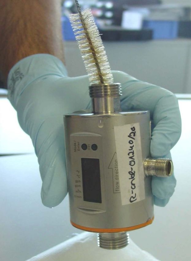
SEMI-AUTOMATED 4 PUMP CONTROLLER

                                                                              Section
                     Safety Instructions                                         A

Every year accidents in the work place maim, kill and injure people. Although it may
be impossible to prevent all accidents, with the right combination of training, operating
practices, safety devices, and operator vigilance, the number of accidents can be
significantly reduced. The purpose of this section is to educate equipment users
about hazards, unsafe practices, and recommended hazard avoidance techniques.

If any of the required regularly scheduled maintenance is located above the reach of
the operator, they should follow the companies normal safe practices of reaching that
particular height, utilizing the companies specified equipment and following normal
safety precautions.

When working with treatment chemicals, operators should always wear protective
gloves, safety glasses, and follow the companies safety precautions in the case of
any spillage or operator contamination.

                          SAFETY WORDS AND SYMBOLS
It is very important that operators and maintenance personnel understand the words
and symbols that are used to communicate safety information. Safety words, their
meaning and format, have been standardized for U.S. manufacturers and published
by the American National Standards Institute (ANSI). The European Community (E.C.)
has adopted a different format based on the International Standards Organization
(I.S.O.) and applicable machinery directives. Both formats are presented below.
Graphic symbols are not standardized, but most manufacturers will use some variation
of the ones seen in this manual.

                            MOTS ET SYMBOLES SÉCURITÉ
Il est très important que les opérateurs et le personnel d'entretien à comprendre les
mots et les symboles qui sont utilisés pour communiquer des informations de sécurité.
Mots de sécurité, de leur signification et le format, ont été normalisés pour les
fabricants américains et publié par l' American National Standards Institute ( ANSI ).
La Communauté européenne (CE ) a adopté un format différent sur la base de
l'Organisation internationale de normalisation ( ISO ) et des directives de machines
applicables. Les deux formats sont présentés ci-dessous. Les symboles graphiques
ne sont pas standardisés, mais la plupart des fabricants utilisent une variante de ceux
observés dans ce manuel.

                                                                                   Page 5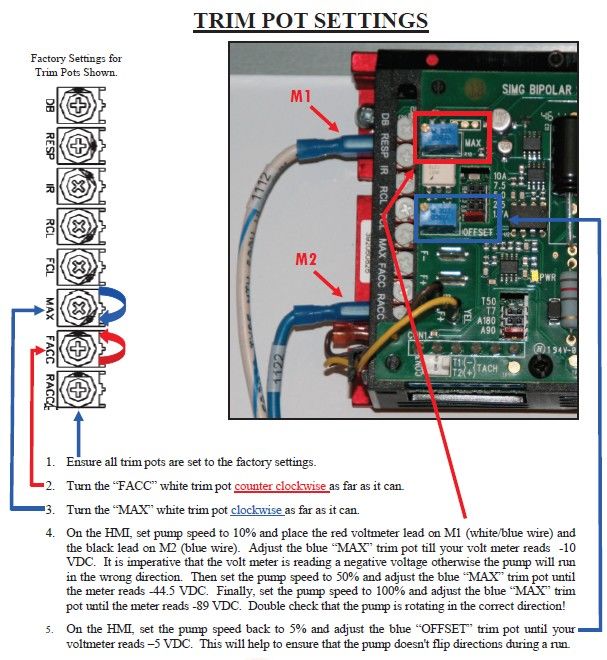
SEMI-AUTOMATED 4 PUMP CONTROLLER

               Indicates an imminently hazardous situation which, if not
               avoided, will result in death or serious injury.

               Indique une situation extrêmement dangereuse qui, si pas
! DANGER       évitée, entraînera la mort ou des blessures graves.

               Indicates a potentially hazardous situation which, if not avoided,
               could result in death or serious injury.

               Indique une situation potentiellement dangereuse qui, si pas
! ATTENTION    évitée, pourrait entraîner la mort ou des blessures graves.

                      Indicates a potentially hazardous situation which, if not
                      avoided, may result in minor or moderate injury and/or
                      property damage.

                      Indique une situation potentiellement dangereuse qui,
! AVERTISSEMENT       si pas évitée, peut entraîner des blessures mineures ou
                      modérées et / ou des dommages.

   SAFETY             Provides additional information that the operator needs to
INSTRUCTIONS          be aware of to avoid a potentially hazardous situation.

CONSIGNES             Fournit des informations supplémentaires que l'opérateur
                      doit être conscient de d'éviter une situation
DE SÉCURITÉ           potentiellement dangereuse.

           Notice is used to notify people of important installation, operation or
NOTICE     maintenance information which is not hazard related.

           Avis est utilisé pour informer les gens des informations de
 AVIS      maintenance qui ne est pas danger lié importante installation,
           l'exploitation ou.

  Page 6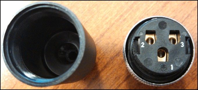
SEMI-AUTOMATED 4 PUMP CONTROLLER

Mandatory Lockout Power Symbol. Disconnect, lockout and
tagout electrical and other energy sources before inspecting, cleaning
or performing maintenance on this panel.

Symbole de puissance verrouillage obligatoire. Débranchez,
de verrouillage et de déconsignation énergie électrique et d'autres
sources avant d'inspecter, de nettoyage ou de la maintenance de
ce panneau.

International Safety Alert Symbol. The exclamation point (!)
surrounded by a yellow triangle indicates that an injury hazard exists.
However, it does not indicate the seriousness of potential injury. The
exclamation point (!) is also used with the DANGER, WARNING and
CAUTION symbols so the potential injury is indicated.

Sécurité Symbole International Alert . Le point d'exclamation ( ! )
Entouré par un triangle jaune indique que un risque de blessure
existe . Cependant, il ne indique pas la gravité des blessures
potentielles. Le point d'exclamation ( ! ) Est également utilisé avec
les symboles DANGER, AVERTISSEMENT et ATTENTION de
sorte que le risque de blessure est indiqué.

Electrocution Hazard Symbol. This symbol indicates that an
electrocution hazard exists. Serious injury or death could result
from contacting high voltage.

Symbole de danger d'électrocution . Ce symbole indique qu'un
danger d'électrocution existe. Des blessures graves ou la mort
pourraient résulter de contact haute tension.

                                                                 Page 7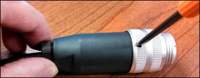
SEMI-AUTOMATED 4 PUMP CONTROLLER

                  International Electrocution Hazard. This symbol indicates that
                  an electrocution hazard exists. Serious injury or death could result
                  from contacting high voltage.

                  Danger d'électrocution international. Ce symbole indique qu'un
                  danger d'électrocution existe. Des blessures graves ou la mort
                  pourraient résulter de contact haute tension.

                  Mandatory Read Manual Action Symbol. (I.S.O. format) This
                  symbol instructs personnel to read the Operators Manual before
                  servicing or operating the equipment.

                  Obligatoire Lire Symbole d'action Manuel. ( Format ISO )
                  Ce symbole indique le personnel de lire le manuel de l'opérateur
                  avant de réparer ou d'utiliser l'équipement.

                  Mandatory Read Manual Action Symbol. This symbol instructs
                  personnel to read the Operators Manual before servicing or
                  operating the equipment.

                  Obligatoire Lire Symbole d'action Manuel . Ce symbole indique
                  le personnel de lire le manuel de l'opérateur avant de réparer ou
                  d'utiliser l'équipement.

                        LOCKOUT / TAGOUT PROCEDURES
Lockout/Tagout is the placement of a lock/tag on an energy isolating device in
accordance with an established procedure. When taking equipment out of service to
perform maintenance or repair work, always follow the lockout / tagout procedures as
outlined in ANSI Z344.1 and/or OSHA Standard 1910.147. This standard “requires
employers to establish a program and utilize procedures for affixing appropriate
lockout devices or tagout devices to energy isolating devices and to otherwise disable
machines or equipment to prevent unexpected energizing, start-up, or release of
stored energy in order to prevent injury to employees.”

    Page 8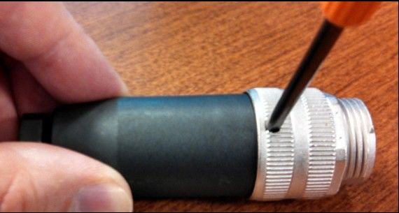
SEMI-AUTOMATED 4 PUMP CONTROLLER
               LES PROCEDURES DE VERROUILLAGE / ETIQUETAGE
Verrouillage / étiquetage est le placement d'un verrouillage / tag sur un dispositif
d'isolement de l'énergie conformément à une procédure établie. Lors de la prise hors
service des équipements pour effectuer la maintenance ou de réparation, toujours
suivre les procédures de verrouillage / débranchement comme indiqué dans la norme
ANSI Z344.1 et / ou la norme OSHA 1910.147. Cette norme "oblige les employeurs
à établir un programme et appliquer des procédures pour la fixation des dispositifs
de verrouillage appropriés ou des dispositifs déconsignation à l'énergie dispositifs
d'isolement et d' autre machines ou équipements désactiver pour éviter énergisant
inattendu, start-up, ou la libération de l'énergie stockée dans le but de prévenir les
blessures aux employés."

                                  HAZARD REVIEW
                                          RISQUE EXAMEN
                                        Electrocution Hazard
                 Electrocution accidents are most likely to occur during maintenance
                 of the electrical system or when working on or near exposed high
                 voltage wiring. This hazard does not exist when the electrical power
                 has been disconnected, properly locked, and tagged out.

                                        Risque d'électrocution

                 Les accidents d'électrocution sont les plus susceptibles de se
                 produire lors de la maintenance du système électrique ou pour
                 travailler sur ou à proximité du câblage haute tension exposé.
                 Ne existe pas ce danger lorsque l'alimentation électrique a été
                 déconnecté, bien verrouillé et étiquetés sur.

                                            Automatic Start Hazard
                          This equipment may be controlled by an automated
                          system and may start without warning. Failure to properly
                          disconnect, lockout, and tagout all energy sources of
                          remotely controlled equipment creates a very hazardous
                          situation and could cause injury or even death.
                          PLEASE STAY CLEAR AND BE ALERT.
                                        Démarrer danger automatique
                Cet équipement peut être contrôlé par un système auto
                matisé et peut démarrer sans avertissement. Sources de
                l'équipement contrôlé à distance non débranché
! AVERTISSEMENT correctement, lock-out, et tous déconsignation énergie crée
                une situation très dangereuse et pourrait causer des
                blessures ou même la mort. Se IL VOUS PLAÎT rester à
                l'écart et d'être vigilant.

                                                                                   Page 9
SEMI-AUTOMATED 4 PUMP CONTROLLER
YOU are responsible for the SAFE operation and maintenance of your USC, LLC
Equipment. YOU must ensure that you and anyone else who is going to operate,
maintain or work around the Equipment be familiar with the operating and maintenance
procedures and related SAFETY information contained in this manual. This manual will
take you step-by-step through your working day and alert you to good safety practices
that should be adhered to while operating the Equipment.
Remember, YOU are the key to safety. Good safety practices not only protect you,
but also the people around you. Make these practices a working part of your safety
program. Be certain that EVERYONE operating this equipment is familiar with the
recommended operating and maintenance procedures and follows all the safety
precautions. Most accidents can be prevented. Do not risk injury or death by ignoring
good safety practices.
Equipment owners must give operating instructions to operators or employees
before allowing them to operate the machine, and at least annually thereafter
per OSHA (Occupational Safety and Health Administration) regulation 1928.57.
The most important safety device on this equipment is a SAFE operator. It is the
operator’s responsibility to read and understand ALL Safety and Operating
instructions in the manual and to follow them. All accidents can be avoided.
A person who has not read and understood all operating and safety instructions is
not qualified to operate the machine. An untrained operator exposes himself and
bystanders to possible serious injury or death.
Do not modify the equipment in any way. Unauthorized modification may impair
the function and/or safety and could affect the life of the equipment.
Think SAFETY! Work SAFELY!
GENERAL SAFETY
1. Read and understand the operator’s manual and all safety labels
before operating, maintaining, adjusting or unplugging the
Equipment.
2. Only trained persons shall operate the Equipment. An untrained
operator is not qualified to operate the machine.
3. Have a first-aid kit available for use should the need arise, and
know how to use it.
Page 10SEMI-AUTOMATED 4 PUMP CONTROLLER
4. Provide a fire extinguisher for use in case of an accident. Store in
a highly visible place.
5. Do not allow children, spectators or bystanders within hazard area
of machine.
6. Wear appropriate protective gear. This includes but is not limited
to:
A hard hat
Protective shoes with slip resistant soles
Protective goggles
Heavy gloves
Hearing protection
Respirator or filter mask
7. Place all controls in neutral or off, stop motor, and wait for all
moving parts to stop. Then disable power source before servicing,
adjusting, repairing, or unplugging.
8. Review safety related items annually with all personnel who will be
operating or maintaining the Equipment.
OPERATING SAFETY:
1. Read and understand the operator’s manual and all safety labels before using.
2. Disconnect and disable electrical supply completely and wait for all moving parts to
stop before servicing, adjusting, repairing or unplugging.
3. Clear the area of bystanders, especially children, before starting.
4. Be familiar with the machine hazard area. If anyone enters hazard area, shut down
machine immediately. Clear the area before restarting.
5. Keep hands, feet, hair and clothing away from all moving and/or rotating parts.
6. Stay away from overhead obstructions and power lines during operation and
transporting. Electrocution can occur without direct contact.
7. Do not operate machine when any guards are removed.
8. Inspect welds and repair if needed.
Page 11SEMI-AUTOMATED 4 PUMP CONTROLLER
PLACEMENT SAFETY
1. Move only with the appropriate equipment
2. Stay away from overhead power lines when moving equipment. Electrocution can
occur without direct contact.
3. Be familiar with machine hazard area. If anyone enters hazard areas, shut down
machine immediately. Clear the area before restarting.
4. Operate the equipment on level ground free of debris. Anchor the equipment to
prevent tipping or upending.
Before placement of the equipment, be sure that ground is
reasonably level. The equipment may topple or work
improperly if the ground is too uneven, damaging the
equipment and / or causing personal injury.
Avant de placement de l'équipement, assurez-vous que sol
! AVERTISSEMENT est relativement plat. L'équipement peut tomber ou mal
fonctionner si le sol est trop inégale, endommager
l'équipement et / ou causer des blessures.
MAINTENANCE SAFETY
1. Review the operator’s manual and all safety items before
working with, maintaining or operating the equipment .
2. Place all controls in neutral or off, stop motors, disable power
source, and wait for all moving parts to stop before servicing,
adjusting, repairing or unplugging.
3. Follow good shop practices:
Keep service area clean and dry.
Be sure electrical outlets and tools are properly grounded.
Use adequate light for the job at hand.
4. Keep hands, feet, hair and clothing away from all moving and/or rotating parts.
5. Clear the area of bystanders, especially children, when carrying out any
maintenance and repairs or making any adjustments.
6. Before resuming work, install and secure all guards when maintenance work is
completed.
7. Keep safety labels clean. Replace any sign that is damaged or not clearly visible.
Page 12SEMI-AUTOMATED 4 PUMP CONTROLLER
SAFETY LABELS
1. Keep safety labels clean and legible at all times.
2. Replace safety labels that are missing or have become illegible.
3. Replaced parts that displayed a safety label should also display the current label.
4. Replacement safety labels are available. Contact USC at (785) 431-7900 .
How to Install Safety Labels:
Be sure that the installation area is clean and dry.
Be sure temperature is above 50oF (10oC).
Decide on the exact position before you remove the backing paper.
Remove the smallest portion of the split backing paper.
Align the sign over the specified area and carefully press the small portion with
the exposed sticky backing in place.
Slowly peel back the remaining paper and carefully smooth the remaining
portion of the sign in place.
Small air pockets can be pierced with a pin and smoothed out using the piece
of sign backing paper.
Located on the USC equipment you will find safety labels.
Always be sure to read and follow all directions on the labels.
Situé sur l'équipement USC vous trouverez des étiquettes
! AVERTISSEMENT de sécurité. Veillez à toujours lire et suivre toutes les
instructions sur les étiquettes.
Guards provided with USC equipment are to remain in place
during operation.
! AVERTISSEMENT Gardes fournis avec des équipements USC doivent rester
en place pendant le fonctionnement.
Page 13SEMI-AUTOMATED 4 PUMP CONTROLLER
Section
B Installation
HIGH VOLTAGE ~ Always disconnect the power source
before working on or near the control panel or lead wires.
HAUTE TENSION ~ Toujours débrancher la source
! DANGER d'alimentation avant de travailler sur ou près du panneau de
commande ou les câbles.
HIGH VOLTAGE ~ Use insulated tools when making
adjustments while the controls are under power.
HAUTE TENSION ~ Utilisez des outils isolés lors des réglages,
! DANGER tandis que les commandes sont sous tension.
Permanent installation may require additional electrical cords,
NOTICE chemical tubing, and air lines, since each installation is unique.
Installation permanente peut exiger cordons électriques, des
AVIS tubes supplémentaires chimique, et les conduites d'air, puisque
chaque installation est.
USC equipment may operate within a Group II, Division 2, Class G hazardous area
which contains seed dust. If so, the equipment must be certified for use in this area.
To avoid the possibility of an explosion ignited by static electricity, all USC equipment
should be grounded by attaching a bonding strip to the metal frame and securing that
strip to the factory ground point.
If labeled accordingly, USC products are designed to comply with CSA 22.1 for use
in a Class II, Division 2, Group G environment. When connecting the USC system
power cord into a power supply, first determine if the supply is also within the
hazardous area where the USC system is located. If so, we recommend that the
power be hard wired into the source. Do not use a standard electrical plug for this
purpose. For other acceptable methods of connecting to a power source, or any other
additional miscellaneous equipment to the USC system within a hazardous location,
please consult CSA 22.1, Section 18-200 and 18-274. Review the appropriate section
and ensure compliance with one of the options given.
When connecting to USC equipment from a remote location, and the USC equipment
is in a hazardous Class II, Group G environment, customers are advised to follow the
requirements within CSA 22.2 no. 25. More details may also be found in CSA 22.1
18-252 (wiring methods). There are various options covered within this section for
wiring in a Class II, Group G (dust) environment. Select the best method suited for
your specific location.
Page 14SEMI-AUTOMATED 4 PUMP CONTROLLER
équipements USC peut fonctionner dans un Groupe II, Division 2, Classe G zone
dangereuse qui contient la poussière des semences. Si oui, l'équipement doit être
certifié pour une utilisation dans ce domaine. Pour éviter la possibilité d'une explosion
enflammé par l'électricité statique, tous les équipements USC doit être mis à la terre
en attachant une bande de liaison à la structure métallique et la sécurisation cette
bande au point de masse du fabricant.
Si étiquetés en conséquence, les produits USC sont conçus pour être conformes
à la norme CSA 22.1 pour une utilisation dans une Classe II, Division 2, Groupe G
environnement. Lors du raccordement du USC alimentation du système cordon dans
une alimentation, d'abord déterminer si l'offre est également dans la zone dangereuse
où se trouve le système USC. Si oui, nous recommandons que le pouvoir soit câblé
dans la source. Ne pas utiliser une prise électrique standard à cet effet. Pour les
autres méthodes acceptables de se connecter à une source d'alimentation, ou tout
autre matériel divers supplémentaire au système USC dans un endroit dangereux,
se il vous plaît consulter la norme CSA 22.1, Section 18-200 et 18-274. Consultez
la section appropriée et assurer la conformité avec l'une des options proposées.
Lors de la connexion à l'équipement USC depuis un emplacement distant et
l'équipement USC est dans une classe dangereuse II, Groupe G environnement, les
clients sont invités à suivre les exigences dans CSA 22.2 no. 25. Plus de détails
peuvent également être trouvés dans 22,1 CSA 18-252 ( Les méthodes de câblage).
Il existe diverses options couvertes dans cette section pour le câblage dans une
Classe II, Groupe G (poussière ) environnement. Sélectionnez la meilleure méthode
adaptée pour votre emplacement spécifique.
PLACEMENT & INSPECTION
The following steps outline the initial set-up of your Semi-Automated 4 Pump
Controller:
1. Clear the area of bystanders, especially small children, before moving.
2. Be sure there is enough clearance from overhead obstructions and power lines
or other equipment to move the machine into its working position.
3. Place the Semi-Automated 4 Pump Controller in the desired position on a level
surface close to the pump stands it will be controlling.
4. Inspect the Semi-Automated 4 Pump Controller thoroughly for screws, bolts,
fittings, etc. which may have come loose during shipping.
Page 15SEMI-AUTOMATED 4 PUMP CONTROLLER
USC highly recommends that the Semi-Automated 4 Pump
NOTICE Controller be set up inside a building or any covered structure
to protect the machine from weathering.
USC recommande fortement que le contrôleur 4 pompe semi-
automatique être mis en place à l'intérieur d'un bâtiment ou d'une
AVIS structure couverte pour protéger la machine contre les intempéries.
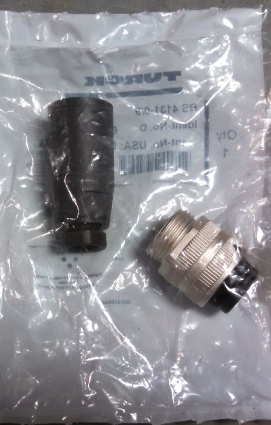
SETTING DC PUMP MOTORS
Each pump motor cable requires this plug (USC P/N 03-08-0324) which mates with a
female plug (USC P/N 03-06-0087) on bottom of control panel. This panel only works
with DC Motors. Pin configuration shown at bottom of page.
Page 16SEMI-AUTOMATED 4 PUMP CONTROLLER
SETTING DC PUMP MOTORS
1. Line holes up so you can insert your small screwdriver into the part. Rotate the
screwdriver side counter clockwise (while holding the black side) to separate.
2. Strip the black insulation back 2.50 inches from the motor wires. Loosen the black
nut, insert Motor wire as shown.
3. Wire motor leads into the correct terminations per your schematic. For USC pump
motors, 1 = Ground, 2 = White, and 3 = Black.
4. Line holes up so you can insert your small screwdriver into the part. Rotate the
screwdriver side clockwise (while holding the black side) to reassemble. Tighten
the black nut back down until the cord grip is tight on the insulation (page 18, top).
Page 17SEMI-AUTOMATED 4 PUMP CONTROLLER
SETTING DC PUMP MOTORS
5. Connect the cable to one of the four mating connectors on the bottom of the control
panel. Turn the power back on to the panel. Place the pump you just wired in
HAND mode. Check the pump, if it is running forward you are ready to use your
pump stand. If the motor is running backwards you will need to turn off power and
swap the black and white wires. Place the pump back in HAND mode. If you are
still having problems with your pump, please call 785-431-7900 and ask to speak
with a service technician.
5
This program will work with Volumetric Flow Meters IFM SM6000
and SM6001, as well as Mass Flow Meter E&H 80E08. All three flow
NOTICE meters require a patch cable (03-08-0292) that will connect the Flow
Meter to the control panel. The patch cable is included with USC
pump stands or may be ordered separately.
Ce programme travaillera avec compteurs volumétriques de débit
IFM SM6000 et SM6001, ainsi que Débitmètre massique E & M
80E08. Tous les trois débitmètres nécessitent un câble de
AVIS raccordement (03-08-0292) qui reliera le débitmètre au panneau
de commande. Le câble de raccordement est inclus avec USC
pieds de pompe ou peut être commandé séparément.
Page 18SEMI-AUTOMATED 4 PUMP CONTROLLER
DC PUMP BOARD SETTINGS
For part numbers 03-01-0163 and 03-10-0164 (Signal Isolator and Regenerative Drive)
1. Remove jumper J1.
2. Set jumper J2 to 1.7A or 2.5A per schematic. (Sets Motor Current)
3. Set jumper J3 to A90. (Sets Motor Voltage)
4. Set jumper J1A and J1B to 115V. (Sets AC Line Voltage)
Page 19SEMI-AUTOMATED 4 PUMP CONTROLLER
DC PUMP BOARD SETTINGS
For part numbers 03-01-0163 and 03-10-0164 (Signal Isolator and Regenerative Drive)
1. Ensure all trim pots are set to the factory settings.
2. Turn the FACC white trim pot counter clockwise as far as it can.
3. Turn the MAX white trim pot clockwise as far as it can.
4. On the HMI, set pump speed to 10% and place the red volt meter lead on M1 (white/blue wire)
and the black lead on M2 (blue wire). Adjust the blue MAX trim pot until your volt meter reads
–10 VDC. It is imperative that the volt meter is reading a negative voltage otherwise the pump
will run in the wrong direction. Then set the pump speed to 50% and adjust the blue MAX trim
pot until the meter reads –44.5 VDC. Finally, set the pump speed to 100% and adjust the blue
MAX trim pot until the meter reads -89 VDC. Double check that the pump is rotating in the
correct direction.
5. On the HMI, set the pump speed back to 5% and adjust the blue OFFSET trim pot until your
volt meter reads –5 VDC. This will help to ensure that the pump does not flip directions during
a run.
Page 20SEMI-AUTOMATED 4 PUMP CONTROLLER
Section
Mechanical Operation C
SEMI-AUTOMATED 4 PUMP CONTROLLER OVERVIEW
ON / OFF
Power
Switch
HMI Touch
Screen
4 - Pump Main
Control Panel
Adjustable
Hardware
Adjustable Control
Panel Stand
Page 21SEMI-AUTOMATED 4 PUMP CONTROLLER
Section
D Electrical Operation
HIGH VOLTAGE ~ Always disconnect the power source
before working on or near the control panel or lead wires.
HAUTE TENSION ~ Toujours débrancher la source d'alimentation
! DANGER avant de travailler sur ou près du panneau de commande ou les
câbles.
HIGH VOLTAGE ~ Use insulated tools when making
adjustments while the controls are under power.
HAUTE TENSION ~ Utilisez des outils isolés lors des réglages,
! DANGER tandis que les commandes sont sous tension.
AUTHORIZED PERSONNEL only shall work on the control panel.
Never allow anyone who has not read and familiarized
themselves with the owner’s manual to open or work on
the control panels.
Seules personnes autorisées doivent travailler sur le panneau de
! ATTENTION commande. Ne jamais laisser quelqu'un qui n'a pas lu et se sont
familiarisés avec le manuel d'ouvrir ou de travail du propriétaire
This section provides a general overview and description of the operator controls for
the Semi-Automated 4 Pump Controller. The system is configurable to operate with
USC pump stands, Non-USC pump stands or a combination of the two. The Non-USC
pump stands must have a DC pump motor.
USC recommends the use of a surge protection device with a minimum rating of
400 Joules for all automated main control panels.
NOTICE USC recommande l'utilisation d'un dispositif de protection
contre les surtensions avec une cote minimale de 400 joules
pour tous les principaux panneaux de contrôle automatisés.
AVIS
Page 22SEMI-AUTOMATED 4 PUMP CONTROLLER
General Panel Descriptions
The Semi-Automated 4 Pump Controller connects to and controls up to 4 individual
pump stands. Each individual pump is plug connected to the control panel.
The flow meters are plug connected. The panel contains the PLC (Programmable
Logic Controller) as well as the HMI (Human Machine Interface) touch screen.
The operator is able to control the entire system through the HMI. Power to this
panel is supplied from a standard 110V plug.
The following pages explain the function of the touch screen controls.
USC START UP SCREEN
While the system is booting up, the touch screen will display a timer bar at the bottom
of the Start Up Screen. Once the timer bar reaches the end it will disappear and be
replaced with flashing piece of text that reads CLICK TO CONTINUE. Select any
where on the screen and it will advance to the Main screen.
This screen also displays the version of the software currently installed.
Page 23SEMI-AUTOMATED 4 PUMP CONTROLLER
MAIN SCREEN
1 2
3
4
5
6
7 8 9 10
1. PUMP IDENTIFICATION: Displays which pump stand main screen the operator is
in by highlighting it in green. It also allows the operator to move from one pump stand
to another without returning to the Overview screen.
2. CHEMICAL STATUS BOX: Displays the name of the active chemical at the top,
as well as the target flow rate and the current flow rate. The totalizer displays the
amount of chemical used and the calibration ratio for the chemical being used.
The H-O-A display in the upper right corner informs the operator of the current active
motor status without having to press the H-O-A button and leaving the main screen
3. CHEMICALS / RECIPES: Pressing this button advances the operator to the
Chemical / Recipes Selection or Editing pop up screen (see page 26).
4. FLOW RATE SETUP: Pressing this button advances the operator to the flow rate
setup screens screen (see page 31).
Page 24SEMI-AUTOMATED 4 PUMP CONTROLLER
MAIN SCREEN
5. OVERVIEW SCREEN: Pressing this button advances the operator to the Overview
screen (see page 33).
6. RESET TOTALIZER: Pressing this button will reset the totalizer display after a run
is complete.
7. MAIN: This button returns the operator to the Main screen from any other screen
in the system.
8. H-O-A: This button advances the operator to the H-O-A screen (see page 34).
9. UTILITIES: This button advances the operator to the Utilities screen
(see page 35).
10. SECURITY: This button advances the operator to the Security screen
(see page 38).
Some of the screens have a round blue button with a question
NOTICE mark in the upper left corner of the screen. Selecting this button
will bring up a help screen covering the functions of that screen.
Page 25SEMI-AUTOMATED 4 PUMP CONTROLLER
CHEMICALS / RECIPE SELECTION AND EDITING SCREEN
1 2
3 4
1. CHEMICAL SELECTION: Press this button and the Chemical Selection screen
appears. (Bottom left) Use the arrows to scroll through the list to find the chemical
you wish to use. The system can store up to 100 different chemical entries. Each
chemical type will have its own name and calibration ratio. When operating in the
Recipe mode, this button will become inactive because the recipe is now dictating
the chemical selection.
2. CHEMICAL EDITING: Pressing this button advances the operator to the
Chemical Editing screen (bottom, right). Select a chemical from the listing to modify
or an unused box to create a new chemical entry. The Chemical Editing screen will
appear (see page 28). This button is always active, even if operating in recipe mode.
Page 26SEMI-AUTOMATED 4 PUMP CONTROLLER
CHEMICALS / RECIPE SELECTION AND EDITING SCREEN
3. SELECT PUMP(S) RECIPE: Press this button and the Select Pumps Recipe
screen appears (Bottom left). Using the up and down arrows the operator may scroll
through the list of recipes and select it. Choosing a recipe will set all pumps to the
preconfigured rates, based upon your Flow Rate Setup settings, for all pumps.
The pumps will be set to AUTO or OFF based on the individual pump settings in the
recipe. The system can store up to 20 recipes. The recipes will appear in the order
they were created.
4. EDIT PUMP(S) RECIPE: Displays the same list as the select screen to allow the
operator to find and edit the recipe (Bottom right). Select the name to modify and the
Recipe Editing screen for that recipe appears (See page 30).
Page 27SEMI-AUTOMATED 4 PUMP CONTROLLER
CHEMICAL EDITING SCREEN
1
4
2
5
6
3
7
1. CHEMICAL NAME: When this button is pushed an alpha numeric keypad
appears allowing the operator to change an existing chemical name. If an unused box
was selected from the list, the name will be blank and the Calibration Ratio will be 1.0.
allowing the operator to enter a new chemical into the system. Once saved, it will be
added to the list.
2. PUMP RATE: This button is only present when recipe mode is enabled. It is the
pump rate that will be used when recipe mode is enabled. A flow rate setup screen
should be interlocked and the recipe pump rates will be used instead.
3. CALIBRATION RATIO: When this button is pushed a numeric keypad appears
allowing the operator to manually enter the multiplier used for flow meter calibration.
4. SCREEN EXIT: This button is used to return to the previous screen.
It’s functionality is the same throughout all of the HMI screens.
5. CALCULATOR: Pressing this button takes the operator to the Calibration
Calculator screen (see page 29).
6. CLEAR: This button deletes the name and resets the Calibration Factor to 1.00.
After a new name and calibration factor has been entered, press the save button.
This is another way to enter a new chemical name in the system.
7. SAVE: Saves any changes to the chemical profile.
Page 28SEMI-AUTOMATED 4 PUMP CONTROLLER
CALIBRATION CALCULATOR SCREEN
5
6
1 7
2 8
3
4 9
1. ACTUAL OUNCES: Pressing this button brings up a keypad used to enter the
actual ounces applied during the calibration procedure (see page 41).
2. TARGET OUNCES: Pressing this button brings up a keypad used to enter the
amount of ounces the system should have been applied.
3. TOTALIZER: This display indicates the amount of chemical the program estimates
it applied on the last run.
4. APPLY: After the actual ounces and target ounces have been entered, the
calculated ratio will be updated. Pressing this button returns the operator to the
chemical editing screen and updates the calibration ratio.
5. SCREEN EXIT: Pressing this button returns the operator to the chemical editing
screen.
6. SELECTED CHEMICAL: This display indicates the name of the chemical for this
calibration.
7. CALCULATED RATIO: This display indicates the amount the current calibration
will be adjusted when the apply button is pressed.
8. CURRENT RATIO: This display indicates the current calibration.
9. DEFAULT: Pressing this button returns all values to the default setting of one.
The actual ounces will always be the amount caught by either a
calibration tube or other measuring device. The target ounces are
the amount that should have been caught in the measuring device.
NOTICE The operator may use the amount they physically measured, or the
totalizer amount. The totalizer amount is the programs estimation
of what the measuring device should have received.
Page 29SEMI-AUTOMATED 4 PUMP CONTROLLER
RECIPE EDITING SCREEN
1
3
2
4 5
1. RECIPE NAME: When this button is pushed an alpha numeric keypad appears
allowing the operator to create or change the recipe name.
2. CHEMICAL SELECTION: Pressing this button returns the operator to the
Chemical Selection editing screen.
3. PUMP MOTOR STATUS: This button toggles between AUTO to include the
chemical in the recipe or OFF to exclude it.
4. CLEAR: This button deletes the recipe and chemical names . After a new name
and chemicals have been entered, press the save button. This is another way to enter
a new chemical name in the system.
5. SAVE: Saves any changes to the recipe profile.
Page 30SEMI-AUTOMATED 4 PUMP CONTROLLER
FLOW RATE SETUP SCREENS
This screen allows the operator to cycle through different modes of operation by
pressing the MODE display box at the top left of the screen. The different modes are
discussed below.
MODE: Off - Allows the operator to
control the pump through the Utilities
screen.
MODE: oz / SCU & SCU / min - Allows
operator to enter the treater seed flow rate
in SCU / min and the chemical application
in oz / SCU for the pump. The system will
convert it to oz / min and display it in the
white box.
MODE: oz / SCU & lb / min - Allows the
operator to enter the Seeds / Unit and
Seed Count boxes as well as enter the
treater seed flow in lb / min and the
chemical application in oz / SCU.
The system will convert it to oz / min
and display it in the white box.
Page 31SEMI-AUTOMATED 4 PUMP CONTROLLER
FLOW RATE SETUP SCREENS
MODE: oz / CWT & SCU / min - Allows
the operator to enter the Seeds / Unit and
Seed Count boxes as well as enter the
treater seed flow in SCU / min and the
chemical application in oz / CWT. The
system will convert it to oz / min and
display it in the white box.
MODE: oz / CWT & lbs / min – Allows the
operator to enter the treater seed flow in
lbs / min and the chemical application in
oz / CWT. The system will convert it to
oz / min and display it in the white box.
MODE: Direct Translation – Allows the
operator to set pump in oz / min. The rate
the user enters will be the rate at which
the pump will operate.
On the right side of this screen is the
Current Batch Run Time(s) option. This
will appear on all of the Flow Rate Setup
screens if the Batch Mode button on the
Tools & Options screen is active.
This option is used when the pump stand
is being used with a Batch Treater.
It allows the operator to set a run time for
each batch that starts when it receives the
start signal from the treater and stops
when the designated time has elapsed.
Page 32SEMI-AUTOMATED 4 PUMP CONTROLLER
OVERVIEW SCREEN
This screen displays the basic information for each of the four pump stands being
controlled by the Universal Semi-Automated 4 Pump Controller simultaneously.
1 2 3
8
4
5
9
6
7
1. PUMP IDENTIFICATION: Displays the number of each individual pump controlled
by the system.
2. CHEMICAL NAME: Displays the name of the chemical currently assigned to each
individual pump.
3. FACTOR: Displays the Calibration Ratio (see page 29).
4. OUNCES PER MINUTE: Displays the ounces of chemical per minute being
applied. It also may be displayed in milliliters.
5. TOTAL OUNCES: Displays in real time the amount of chemical that has been
applied.
6. H-O-A: Displays what mode the pump is in, HAND, OFF or AUTO (see page 34).
7. SPEED CONTROL: The system is able to operate in two different speed control
modes. Flow Rate Mode makes the pump drive to and then lock onto a desired flow
rate. Percentage Mode makes the pump run at pre-defined percentage of the
maximum motor speed.
8. MAIN SCREEN BUTTON: Press any of the four boxes and the operator will be
taken to the main screen (see page 24).
9. PUMP MOTOR RUNNING INDICATOR: When the green box is present, it
indicates that the motor is running. When the green box is flashing on and off, the
motor is running in reverse. If operating in Batch mode, a timer indicating how much
time is left for the batch will appear in the green indicator below the HOA block.
Page 33SEMI-AUTOMATED 4 PUMP CONTROLLER
H-O-A SCREEN
1
1. PUMP H-O-A MODULE: This module controls the function of the pump motors.
The HAND button will place the pump motor on in the manual mode of operation.
When it is active it will turn green. The OFF button will turn the motor off in the manual
mode of operation. When it is active it will turn red. The AUTO button will place the
device in the automatic mode of operation. When it is active it will turn yellow.
This button is used when the pump stand is attached to a seed treater.
This allows the treater to turn the pump on and off at the appropriate time.
Pressing the REVERSE PUMP button will place the pump in HAND mode but the
pump will be running backwards.
Page 34SEMI-AUTOMATED 4 PUMP CONTROLLER
UTILITIES SCREEN
1
2
3
4 5
1. ARROWS: Selecting the arrow buttons allows the operator to scroll through all of
the pumps to set up each one individually.
2. TARGET RATE: When this button is pushed a numeric keypad will appear on the
screen. This allows the operator to set an application target rate in ounces or milliliters
per minute. This option is unavailable while Flow Rate Mode is on any setting other
than OFF.
3. PUMP PERCENTAGE RATE: When this button is pushed a numeric keypad will
appear on the screen, enter a percentage value. This method disregards the flow
meter reading. It drives the pump to a specified percentage of the maximum pump
speed.
4. TOOLS & OPTIONS: Pressing this button takes the operator to the
Tools & Options screen (see page 36).
5. START-UP SCREEN: This button returns the operator to the starter screen
(see page 23).
Page 35SEMI-AUTOMATED 4 PUMP CONTROLLER
TOOLS & OPTIONS SCREEN
1 4
2 5
3
1. SITE ID: Pressing this button brings up the Site Identification screen. Press the
Site Name field and an alpha numeric keyboard will appear for entering the name of
the installation. The Site Description is automatically populated with the description of
the current software loaded. This information will be used by USC service personnel
to verify the customers installation.
2. BATCH MODE: Pressing this button activates Batch Mode. When active it will
turn green. This option is used when the pump stand is attached to a batch treater.
The start signal will be sent from the treater and the pump will start. It will run for the
amount of time pre-set on the Flow Rate Setup screen. See bottom of page 32.
Page 36SEMI-AUTOMATED 4 PUMP CONTROLLER
TOOLS & OPTIONS SCREEN
3. RECIPE MODE: Pressing this button activates Recipe Mode. When active it will
turn green. This option is used when the operator wishes to use a combination of
chemicals defined in the recipe module instead of choosing an individual chemical
(see page 26).
4. USC INSTANT MESSENGER: Pressing this button will advance the operator
to the Instant Messenger screen. This is used by the technical support staff when a
customer calls with a problem. The service technician uses this to remotely connect
to the site and verify the site identification information. This connection can only be
made by USC. Once the link has been established, it may be used to text information
to and from the customer site. This option only functions if the operator has U-Connect
light installed on their laptop or U-Connect Pro is connected to the control panel using
a Thin Client to make the connection.
5. UNIT OF MEASURE: Pressing this button allows the operator to toggle between
US or Metric units of measurement.
Page 37SEMI-AUTOMATED 4 PUMP CONTROLLER
SECURITY SCREEN
1. PASSWORD ENTRY: The operator uses this input to obtain access to the
Setpoints screen. When this button is pressed an alpha numeric keypad will appear.
The password is USC and should only be made accessible to personnel qualified to
operate the system.
2. LOGIN: Pressing this button after the password has been entered will activate the
SETPOINTS button.
3. LOGOUT: Pressing this button will de-activate the Setpoint button.
4. SETPOINTS: Pressing this button advances the operator to the Setpoints screen
(see page 39).
1
2
3 4
Page 38SEMI-AUTOMATED 4 PUMP CONTROLLER
SETPOINTS SCREEN
1 3
2
1. FLOW METER TYPE: Pressing this button toggles between Volumetric, Mass,
Low Flow and the Custom flow meter options to match the type of flow meter being
used with your equipment. If using a Non-USC type pump, it would be set to custom
activating the Custom PID Settings button (see page 40).
2. PUMP FLOW BUTTON: Pressing this button toggles between Low Flow, Base
Flow and High Flow. The low flow setting is configured for the low flow peristaltic
pump assembly. The base setting is configured for one of the three standard pump
configurations. When set to base flow, the # of pumps heads button must be set to
ether 1, 2 or 3 to match the number standard peristaltic pump heads installed.
The high flow setting is configured for the high flow peristaltic pump assembly.
3. # OF PUMP HEADS: Pressing this button toggles between 0, 1, 2 and 3 to be set
to the number of peristaltic pump heads are on the pump stand.
Page 39SEMI-AUTOMATED 4 PUMP CONTROLLER
SETPOINTS SCREEN
4
5
4. ARROWS: Selecting the arrow buttons allows the operator to scroll through all of
the pumps to setup each one individually.
5. CUSTOM PID SETTINGS: Pressing this button advances the operator to the
Custom PID Settings screen. If the flow meter type is set to Custom, the PID settings
may need to be set on this screen. This screen allows the operator to manually enter
custom PID settings for single or multiple head pumps. The system default settings
are shown below. This screen is only used when non-USC pumps are being used
and even then it may not be necessary to make any changes. If the operator has
made changes and wants to return to the default settings, they may change the entry
in the first row and the first column to zero, select the red X to exit the screen.
This resets the screen to the default settings.
Page 40SEMI-AUTOMATED 4 PUMP CONTROLLER
Section
CALIBRATION E
INITIAL PUMP CALIBRATION (USC Pump Stands)
1. Lock down the pump tubing in the pump head.
2. Premix enough liquid for the amount of seed you are treating and pour into the
chemical mix tank. It’s always a good practice to mix up 20% extra slurry to help fill
all the lines.
3. From the Main screen press the Chemical button, then Chemical Editing. From the
Chemical Editing screen, choose the type of chemical. From that screen, verify that
the Calibration Factor is set to one. From the Utilities screen, enter the number of
ounces needed per minute per hundred pounds of seed as the Target Rate
4. Set the return valves to Mix Tank for recirculation. Turn the ON / OFF switch for
the mix tank motor to the ON position. Run it for 15 minutes to ensure that the
chemical mixture within the mix tank is blended completely and any air is removed
from the system.
Select
Chemicals/ Choose
Recipes chemical
name here
Enter Ounces
per Minute
Page 41SEMI-AUTOMATED 4 PUMP CONTROLLER
FLOW METER CALIBRATION (USC Pump Stands)
Due to the composition of some types of chemicals, additional flow meter calibration
may be required. It is recommended that, like other calibration devices, the flow
meter(s) are checked regularly and calibrated when needed. When calibrating the flow
meter(s), each chemical slurry must be checked and adjusted for.
1. To begin the calibration process, fill the appropriate
mix tank with the slurry that is going to be used for
this calibration.
2. Turn the ON / OFF switch for the mix tank motor to
the ON position. From the Utilities screen, enter a
value for the Pump Percentage speed (Example 20)
and check the box to the left. From the HOA
screen, press the HAND button and ensure that the
valves are set to Mix Tank for recirculation. Let the
system run in recirculation mode for 15 minutes.
This will remove any air from the system.
3. Press the Chemical button on the Main screen and
select the correct chemical name.
4. Place the bottom return valve to MIX TANK /
CALIBRATION TUBE. The valve is located on top
of the pump stand (right). Place the top valve to the
CALIBRATION TUBE position. Once the liquid in
the Calibration Tube reaches zero press HAND or
OFF to stop the pump. Press the Reset Totalizer
button to zero out the Totalizer. Press the HAND
button and start the stopwatch simultaneously.
Stop the pump when the stopwatch reaches one
minute. Note the total ounces of chemical that is
in the calibration tube.
5. From the Calibration Calculator screen, enter the
number of the ounces in the Actual Ounces box.
Press the Apply button, then press Save.
The system automatically calculates and places
the amount in the Calibration Ratio box.
6. Repeat the process as necessary and for each
different chemical slurry used.
Page 42SEMI-AUTOMATED 4 PUMP CONTROLLER
Section
Troubleshooting F
TROUBLESHOOTING
Below is a table describing the most frequent problems and solutions with the USC
Semi-Automated 4 Pump Controller. For further assistance, contact the USC Service
department at (785) 431-7900.
Problem Possible Cause Solution
Pump is fluctuating. 1. Restriction in tubing 1. Flush tubing and check filter
2. Filter is plugged or missing for any restrictions.
gasket. 2. Clean filter and check for
gasket.
3. Hoses are worn out.
3. Replace hoses.
Pump will not turn off in AUTO 1. Proximity switch in the 1. Clean proximity switch.
when seed runs out. hopper cone is dirty. 2. Adjust the pump proximity
(USC Seed Treaters) 2. Proximity switch is set too switch sensitivity by turning
sensitive. adjustment screw counter-
clockwise.
Pump will not turn off in AUTO 1. Signal to shut the pump off 1. Check treater control panel to
when seed runs out. is not being sent from the see if signal is being sent to
(Non-USC Seed Treaters) treater. pump controller.
Pump will not turn on in AUTO. 1. Proximity switch in the 1. Make sure proximity switch is
(USC Seed Treaters) hopper cone is not staying staying covered with seed.
covered. 2. Adjust pump proximity switch
2. Proximity switch is not sensitivity by turning the
sensitive enough. adjustment screw clockwise.
3. HMI screen not set to AUTO. 3. Set HMI screen to AUTO.
4. Auxiliary cable not hooked 4. Attach Auxiliary cable from
up. control box to treater control
box.
Pump will not turn on in AUTO. 1. Two pin cable is not 1. Check to see that both
(Non-USC Seed Treaters) connected to the pump ends of the cable are
control panel or the seed properly connected to their
treater. respective control panels.
2. Signal to shut the pump off 2. Check treater control panel
is not being sent from the to see if signal is being sent
treater. to pump controller.
3. HMI screen not set to AUTO. 3. HMI screen not set to AUTO.
Mix Motor will not start 1. Power cord not plugged in. 1. Plug in power cord.
Page 43You can also read