64-Channel Carbon Fiber Electrode Arrays for Chronic Electrophysiology - bioRxiv
←
→
Page content transcription
If your browser does not render page correctly, please read the page content below
bioRxiv preprint first posted online Jul. 9, 2019; doi: http://dx.doi.org/10.1101/697409. The copyright holder for this preprint (which
      was not peer-reviewed) is the author/funder, who has granted bioRxiv a license to display the preprint in perpetuity.
                                It is made available under a CC-BY-NC-ND 4.0 International license.

 64-Channel Carbon Fiber Electrode Arrays for
 Chronic Electrophysiology
 Grigori Guitchounts1,2,3,* and David Cox1,2
 1 Center for Brain Science, Harvard University, Cambridge, Massachusetts 02138, USA
 2 Department   of Molecular and Cellular Biology, Harvard University, Cambridge, MA, 02138, USA
 3 Program in Neuroscience, Harvard University, Cambridge, Massachusetts 02138, USA
 * Correspondence: guitchounts@fas.harvard.edu

 ABSTRACT

  A chief goal in neuroscience is to understand how neuronal activity relates to behavior, perception, and cognition. However,
  monitoring neuronal activity over long periods of time is technically challenging, and limited, in part, by the invasive nature of
  recording tools. While electrodes allow for recording in freely-behaving animals, they tend to be bulky and stiff, causing damage
  to the tissue they are implanted in. One solution to this invasiveness problem may be probes that are small enough to fly under
  the immune system’s radar. Carbon fiber (CF) electrodes are thinner and more flexible than typical metal or silicon electrodes,
  but the arrays described in previous reports had low channel counts and required time-consuming manual assembly. Here we
  report the design of an expanded-channel-count carbon fiber electrode array (CFEA) as well as a method for fast preparation of
  the recording sites using acid etching and electroplating with PEDOT-TFB, and demonstrate the ability of the 64-channel CFEA
  to record from rat visual cortex. We include designs for interfacing the system with micro-drives or flex-PCB cables for recording
  from multiple brain regions, as well as a facilitated method for coating CFs with the insulator Parylene-C. High-channel-count
  CFEAs may thus be an alternative to traditional microwire-based electrodes and a practical tool for exploring the neural code.

 Keywords: carbon fiber, flexible electrodes, minimally-invasive, high density array, neural electrodes, microthread, ultramicro-
 electrode

 Introduction
 In order to understand information processing in the brain, scientists must be able to take reliable measurements from the
 central nervous system (CNS). Ideal methods would allow us to record from all neurons in a brain (108 in a rat or zebra finch1
 at cellular spatial resolution and a temporal resolution on which neurons operate (kHz range) in behaving animals2, 3 . While
 established methods for whole-brain monitoring (e.g. fMRI or PET) typically give poor spatial and temporal resolution, state of
 the art optical methods for imaging of genetically-encoded calcium indicators have yielded cellular spatial resolution while
 recording on the order of ~105 neurons simultaneously at low temporal resolution (~0.5 Hz)4, 5 .
      In contrast to imaging methods, recording neuronal activity using electrodes provides spike-time temporal resolution but low
 cellular yield (state of the art simultaneously recorded neurons using Neuropixels probes is ~3000 neurons using 8 probes, each
 of which contains 384 recording sites, yielding roughly one unit per recording site6, 7 . A further limitation of electrode methods
 is their invasive nature: implanting large electrode arrays damages the tissue the electrodes are meant to record from8, 9 , thus
 limiting the yield of recorded neurons, the longevity of the recording quality, and the ability to track the activity of individual
 neurons over long timescales. These are particularly pressing problems for investigations into how the neural code changes
 during learning, which unfolds over days, weeks or months10–16 ; or for the creation of practical brain-machine-interfaces
 (BMIs), which rely on the stability of recorded signals as well as the underlying neural code in order to decode a patient’s
 thoughts or intended actions11, 17 .
      Metal electrodes have been used for recording single neurons since the mid-20th century18 . These are typically tungsten
 or PtIR wires, on the order of 12.5-50 μm in diameter19, 20 . In rodent work, the typical approach involves arrays composed
 of individual metal wires spun into groups of four (tetrodes) and bundled into groups of up to 40 tetrodes, or 160 channels21 .
 Monolithic silicon devices are a prominent alternative6, 22, 23 that allows for high-density recording sites and high channel counts
 at the expense of a large cross-section (e.g. 70 × 20µm in Neuropixels probes) and high stiffness, which make it a challenge to
 record on long-timescales (however, see Okun et. al24 ).
      Carbon fiber electrode arrays (CFEAs) are an alternative to metal wires or silicon probes. Carbon fibers are thinner and
 more flexible than metal wires typically used, and produce a lower immune response after being implanted into the CNS8, 25, 26 .
 We have previously demonstrated a method for producing multi-channel carbon fiber arrays27 . However, the previous design
bioRxiv preprint first posted online Jul. 9, 2019; doi: http://dx.doi.org/10.1101/697409. The copyright holder for this preprint (which
      was not peer-reviewed) is the author/funder, who has granted bioRxiv a license to display the preprint in perpetuity.
                                It is made available under a CC-BY-NC-ND 4.0 International license.

 was low-channel-count and required time-consuming individual preparation of the recording sites (each electrode’s tip had to
 be fire-sharpened to reduce impedance).
     Here we demonstrate the design of 64-channel CFEAs and a method for bulk preparation of the recording sites. The tips were
 prepared by etching with sulfuric acid in order to increase surface area28, 29 , followed by electroplating with PEDOT-TFB30, 31 ,
 resulting in a dramatically decreased impedance. Recordings in rat visual cortex demonstrate the feasibility of recording neural
 signals with this method. Designs for the 64-channel array are freely available online (https://github.com/guitchounts/electrodes),
 as are designs for flex-PCB-based 16-channel arrays, which allow for recording from multiple brain areas simultaneously.
 Finally, we share designs for laser-cut cartridges that facilitate preparation of CFs for insulation with Parylene-C.

 Figure 1. Assembly and Tip-Preparation. (a) Schematic of 64-channel 3D-printed block (grey) for holding carbon fibers
 (CFs). After threading the CFs through the block, the wells are filled with silver paint. A 70-pin Hirose connector (blue) mates
 with the wells. (b) Photo of assembled array with a US quarter. (c) System for multi-region recording using four 16-channel
 flex-PCB cables and 3D-printed blocks that mate with a PCB adapter for 64-channel recording (top). (d) A 64-channel CFEA
 mounted on a vented-screw-based micro-drive based on design in Anikeeva et. al32 . (e) The recording sites are prepared by
 dipping the CF tips into 93% sulfuric acid for 5 minutes (left). After washing, the tips are electroplated with EDOT/TFB by
 passing a 2nA current for 1 minute per electrode. (f) Impedance of 64 wires on one array after cutting the tips with scissors
 (10.11 ± 0.94 MΩ, median ± s.e.m.) and after treatment with the acid and EDOT/TFB (0.36 ± 1.53 M Ω).

 Results
 Assembly and tip preparation
 In this report, we tested two types of CF arrays: a 16-channel version (assembly of which was reported in27 , and a new,
 64-channel version. For the latter, we designed a 3D-printed plastic block to hold the 64 CFs (Fig. 1a). As in the 16-channel
 version, carbon fibers were threaded through wells at the top of the block, and down through the exit holes on the bottom. The
 pictured design features four exit holes, arranged in a 2x2 grid, but this arrangement can be modified to an 8x2 grid of exit
 holes (design available on github.com) or a single exit hole to bundle the 64 CFs into one. After threading, fibers protrude from
 the top wells and from the bottom exit holes. To connectorize the array, the top-well-protruding wires are first de-insulated
 (by a flame passed swiftly over the wires, to burn off the Parylene-C), then pushed farther into the wells until they no longer
 protrude through the top. Then, a dab of silver paint is applied to the wells; once it spreads through the wells, excess paint is

                                                                                                                                          2/9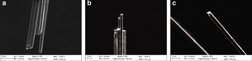
bioRxiv preprint first posted online Jul. 9, 2019; doi: http://dx.doi.org/10.1101/697409. The copyright holder for this preprint (which
      was not peer-reviewed) is the author/funder, who has granted bioRxiv a license to display the preprint in perpetuity.
                                It is made available under a CC-BY-NC-ND 4.0 International license.

 brushed off with a cotton-tipped applicator, and a connector is placed into the wells. In the 64-channel version, this is a 70-pin
 Hirose connector whose pins were folded down manually before insertion (Fig.fig:assemblya). The connector is then glued to
 the plastic block with super glue. The design is configurable to single-block 64-channel arrays (Fig. 1b) or four 16-channel
 arrays on flex-cable PCBs for multi-brain-region recordings (Fig.1c), and is compatible with micro-drive devices (Fig. 1d)32 .

 Figure 2. SEM Images of CF tips. (a) Bundle before treatment. (b) Bundle after acid treatment. (c) Close-up of a single fiber
 after electroplating with EDOT/TFB.

    The impedance of untreated tips is too high for single-unit recordings in a fixed-implant preparation33 , requiring treatment
before recordings can be made. In a previous report, tips were prepared by individual fire-sharpening, which de-insulated
~80 µm along the shaft of each wire, simultaneously sharpening it27 . While successful, this technique is difficult to scale to
high-channel-count arrays. To get around this problem, we turned to chemical treatment of the tips, first etching the tips using
sulfuric acid in order to roughen the tip surface and increase the surface area28, 29 , then electroplating the tips with PEDOT-TFB,
which was previously shown to reduce impedance30, 31 (Fig. 1e). The resulting tips had significantly reduced impedances
(before treatment: 10.11 ± 0.94 MΩ median ± s.e.m. (n = 64 tips from one array), and 0.36 ± 1.53 MΩ in the same tips after
treatment with the acid and PEDOT-TFB (two-sided t-test on impedance before/after treatment of tips: t = 3.42, p = 0.001))
(Fig. 1f). We visualized the effect of this treatment on the tips using serial electron microscopy (Fig. 2).
    The CFEA require individual carbon fibers to be insulated with parylene-C before assembly, which in our previous design
involved a painstaking manual procedure in which individual fibers were mounted on sticky notes and loaded into the parylene
vapor deposition machine (PDS Labcoter 2010). To facilitate this process, we designed coating jigs (Fig. 3a-c) that hold
multiple cartridges (Fig. 3d-e), each of which in turn hold several dozen carbon fibers splayed harp-like across two pieces of
sticky notes. This design (Fig. 3f) can be laser-cut out of plastic and modified to various sizes of cartridges (to hold longer
fibers, for example) or jigs (to hold more or fewer cartridges).

 Long-term recordings
 We tested the longevity of acid/PEDOT-TFB-treated arrays by recording chronically from a 16-channel version of the array
 implanted in rat primary visual cortex (V1). Figure 4 shows examples from one such implanted rat. The left column shows two
 seconds of bandpass-filtered activity four days after the implant surgery (‘Day 4’), while the right column shows activity from
 the same array 55 days later. Spiking activity was prominent across most channels in both recordings, even though the noise
 increased over the two months.

 64-Channel Recording and Responses to Visual Stimulation
 We then proeeded to implant the 64-channel arrays into rat V1. Figure 5 shows example traces from one such recording while
 the animal was behaving freely in the recording chamber. Having determined that we could record spontaneous neuronal
 activity using chronically-implanted 64-channel CF arrays, we sought to determine whether these arrays could capture sensory
 evoked activity as well. For this, we presented a V1-implanted rat with a visual stimulus: flashed cage lights. The rat was free
 to behave in the recording chamber in the dark, while the cage lights were flashed (On for 500 milliseconds, Off for a uniformly
 random time between 400 and 600 milliseconds, for 225 trials.). This strong visual stimulus produced evoked multiunit (MU)
 responses (Fig. 6a,b) and LFPs (Fig. 6c). Figure 6a shows one trial (grey patch indicates time when lights were On); Figure
 6b,c show trial-averaged MU and LFP responses, respectively.

 Discussion
 CFEAs have shown promise in recording from neuronal populations over long timescales but have so far been prepared in small
 channel-count configurations25, 27, 34–36 . It is becoming increasingly clear that in order to understand the brain, neuroscientists

                                                                                                                                          3/9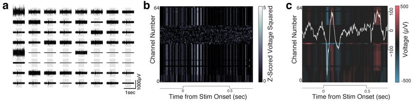
bioRxiv preprint first posted online Jul. 9, 2019; doi: http://dx.doi.org/10.1101/697409. The copyright holder for this preprint (which
      was not peer-reviewed) is the author/funder, who has granted bioRxiv a license to display the preprint in perpetuity.
                                It is made available under a CC-BY-NC-ND 4.0 International license.

 Figure 3. Parylene Coating Jig. (a-c) The assembled jig with two CF cartridges. (d) An example cartridge. Each cartridge
 holds 20-30 CFs, which are strung out across two sticky notes attached to the cartridge. (e) The fibers are placed across the
 cartridge like strings on a harp. (f) Jig and cartridge designs. Each jig holds 11 cartridges, but this design may be expanded as
 long as the jig fits into the Parylene deposition machine (PDS Labcoter 2010).

 Figure 4. Example of 2 seconds of filtered activity traces from a 16-channel CF array chronically implanted in rat visual
 cortex. Left: activity sampled four days after implant surgery. Right: recording from the same animal’s array 55 days later.

 will need to measure larger populations of neurons spread out across multiple brain regions6 (however, see Gao et. al37 ). Our
 results show the feasibility of producing high channel-count, high-density CFEAs and using them to record evoked activity in

                                                                                                                                          4/9
bioRxiv preprint first posted online Jul. 9, 2019; doi: http://dx.doi.org/10.1101/697409. The copyright holder for this preprint (which
was not peer-reviewed) is the author/funder, who has granted bioRxiv a license to display the preprint in perpetuity.
It is made available under a CC-BY-NC-ND 4.0 International license.
rat visual cortex. Further, we have shared designs to implement simultaneous recordings from multiple brain regions using four
16-channel flex-PCB CFEAs (Fig. 1c) and micro-drive-enabled 64-channel arrays (Fig. 1d). We have also designed a jig for
setting up Parylene-C deposition onto the bare CFs (Fig. 3), which we hope will facilitate the implementation of CFEAs by
other labs.
The 64-channel CFEAs are faster to assemble (per channel) than their 16-channel predecessors (~2 hours for the former and
~1 hour for the latter: a 2X improvement from 3.75 to 1.875 minutes/channel). The method of preparing the recording sites
using acid etching and electroplating with PEDOT-TFB further sped up the assembly process over the previous fire-sharpening
technique, which was done on individual fibers and required extensive practice27 .
Figure 5. One second of raw filtered activity recorded from a 64-channel CF array implanted in rat V1 showing multiunit
signals.
CFEA designs have for the most part required manual assembly. This will obviously make recording extremely large
populations of neurons (105-6 ) a challenge. As such, manually-assembled CFEAs may be a more appropriate replacement for
other manually-made electrodes like tetrodes, rather than arrays manufactured using nanotechnology6, 22, 23 , which may soon be
able to accommodate thousands of recording sites. Still, CFEAs are smaller and more flexible than most fabricated arrays and
produce a smaller immune response than larger implants9 . CFEAs can, in principle, be manufactured using automated systems,
and some efforts are underway to implement those38 .
Electrode arrays are currently the best tool for investigating neuronal circuits continuously (i.e. 24/7) over long periods of
time in freely behaving animals. However, whether electrode arrays of any kind will be the method to record all the neuronal
activity in a brain is still unknown. Arrays designed to capture the entirety of neuronal activity in a vertebrate brain would
need to be quite noninvasive indeed; they would also need to capture the activity of millions of neurons, which would require
multiplexing and digitization near the recording sites39 .
Alternatives to electrodes might be optical methods, which are currently limited in their ability to image deep brain
structures40 . Imaging of calcium indicators has a limited temporal resolution because of molecular binding kinetics41 ; this
problem may be avoided by voltage sensors, but those indicators currently have low signal quality42, 43 (but see Adam et. al44 ,
and in principle suffer from the same depth imaging and bleaching problems as calcium indicators. One radically different
approach is molecular barcoding, in which neuronal activity is recorded by a ‘molecular ticker-tape’ that tracks changes in
intracellular calcium concentration by making insertions into a cell’s DNA45, 46 . For now, perhaps the best way to get around
the limitations of each technique is to use multiple complementary tools, investigating local circuits with electrode arrays after
a brain region of interest is identified using whole-brain low-temporal-resolution methods like calcium imaging or fMRI.
5/9bioRxiv preprint first posted online Jul. 9, 2019; doi: http://dx.doi.org/10.1101/697409. The copyright holder for this preprint (which
was not peer-reviewed) is the author/funder, who has granted bioRxiv a license to display the preprint in perpetuity.
It is made available under a CC-BY-NC-ND 4.0 International license.
Figure 6. Visual cortex responses to visual stimulation. The stimulus was a 500-millisecond light flash delivered while the rat
moved freely in the recording chamber. (a) Filtered raw traces across 64 CF electrodes during one stimulation trial (grey patch
symbolizes the duration of the light flash) showing multiunit (MU) responses to the stimulus. (b) Mean MU response across
225 trials of the light flash (filtered traces were z-scored, squared, and smoothed with a gaussian filter). (c) Mean LFP (300 Hz
low-pass filtered) response across the same trials (white line: mean LFP response across channels).
Methods
Animals
The care and experimental manipulation of all animals were reviewed and approved by the Harvard Institutional Animal Care
and Use Committee (Protocol #27-22). Experimental subjects were female Long Evans rats 3 months or older, weighing
300-500 grams ( n = 3, Charles River). One rat was implanted with a 16-channel array; two were implanted with 64-channel
arrays.
Carbon Fibers, Array Assembly, and Tip Preparation
In this report, we used 4.5µm diameter carbon fibers (UMS2526, Goodfellow USA), as reported previously27 . Epoxy sizing
was removed either by heating the fibers to 400 C in a kiln, or by soaking the fibers in acetone >24 hours47 . To insulate the
fibers with Parylene-C (di-chloro-di-p-xylylene) (Paratronix Inc, Westborough MA), we laid the fibers out onto sticky notes
attached to plastic cartridges (Fig. 3) and coated the fibers with ~4.5µm layer of Parylene-C using chemical vapor deposition in
a PDS-2010 Labcoter machine (Specialty Coating Systems, http://scscoatings.com/), as described previously27 .
The fibers were then threaded through 3D-printed plastic blocks, which were custom-designed in SolidWorks (Dassault
Systèmes SolidWorks Corporation, Waltham, MA) and manufactured using stereolithography (Realize Inc, Noblesville, IN)
(designs available on https://github.com/guitchounts/electrodes). The fibers were left protruding ~1mm from the top of the
plastic block and were then deinsulated with a lighter flame, after which they were threaded further into the block until no
longer protruding. Connectorization was achieved by flooding the block’s wells with silver paint (MG Chemicals, #842-20g)
and attaching a Hirose DF40 connector (Digi-key, H11630CT-ND).
The recording sites were prepared by cutting the array bundles to the desired length for implantation (~1mm for the
visual cortex implants described here) using serrated scissors (Fine Science Tools, 14058-11), then dipping the tips into
99% sulfuric acid (Sigma, 339741-500ML) for 5 minutes, then (after washing any remaining acid off with water), by
electroplating with PEDOT-TFB30, 31 by applying a 2nA current via a 10V power supply in series with a 5000MΩ resistor
(Digikey, SM102035007FE-ND), for 1 minute (for a total charge delivery of 120nC) per electrode25 . The electroplating solution
consisted of 0.01M EDOT (Sigma, 483028-10G) and 0.1M tetrabutylammonium tetrafluoroborate (TFB) (Sigma, 86896-25G)
in acetonitrile (Sigma, 360457-500ML). The impedance was tested at 1kHz using an Intan-based headstage and OpenEphys
GUI (http://www.open-ephys.org/gui/).
Surgery
Animals were anesthetized with 2% isoflurane and placed into a stereotaxic apparatus (Knopf Instruments). Care was taken
to clean the scalp with Povidone-iodine swabsticks (Professional Disposables International, #S41125) and isopropyl alcohol
(Dynarex #1204) before removing the scalp and cleaning the skull surface with hydrogen peroxide (Swan) and a mixture
of citric acid (10%) and ferric chloride (3%) (Parkell #S393). Three skull screws (Fine Science Tools, #19010-00) were
screwed into the skull to anchor the implant. A 0.003” stainless steel (A-M Systems, #794700) ground wire was inserted ~2mm
tangential to the brain over the cerebellum.
The arrays were targeted to right V1, ranging ~6-8 mm posterior to bregma, 4.5 mm ML, reaching layer 2/3 at 0.6 mm
DV. After electrodes were inserted into the brain, the craniotomy was covered with Puralube vet ointment (Dechra) and the
6/9bioRxiv preprint first posted online Jul. 9, 2019; doi: http://dx.doi.org/10.1101/697409. The copyright holder for this preprint (which
was not peer-reviewed) is the author/funder, who has granted bioRxiv a license to display the preprint in perpetuity.
It is made available under a CC-BY-NC-ND 4.0 International license.
electrodes were glued down with Metabond (Parkell). Post-operative care included twice-daily injections of buprenex (0.05
mg/kg Intraperitoneal (IP)) and dexamethasone (0.5 mg/kg IP) for three days.
Electrophysiology
Electrode signals were acquired at 30 kHz using either a 16-channel Intan RHD2132 headstage, or a custom Intan-based
64-channel headstage48 and Opal-Kelly FPGAs (XEM6010 with Xilinx Spartan-6 ICs). LFPs and spikes were extracted
following procedures described in Dhawale et al48 . The LFP signals were downsampled to 300Hz by two applications of a
fourth order 5-fold decimating Chebychev filter followed by a single application of a fourth order 4-fold decimating Chebychev
filter. The 16-channel data were acquired using the OpenEphys GUI49 .
In addition to the 64-channel CFEAs, we designed a 64-channel system for recording with four 16-channel arrays in
multiple brain regions. The 16-channel flex-PCB (Fig. 1c) mates with a miniature 16-channel 3D-printed plastic block that
holds the CFs. The connector side holds a 20-pin Hirose DF40 connector (Digi-key, H11618CT-ND) that interfaces with a
breakout PCB that holds four mating 20-pin connectors (Digi-key, H11619CT-ND) on one side and a 70-pin DF40 connector
(Digi-key, H11630CT-ND) on the other. The breakout board thus connects four flex-PCB arrays to one 64-channel headstage.
The 64-channel CFEAs were also adapted for microdrive-based recordings based on the optetrode design in Anikeeva et. al32
(Fig. 1 d).
Behavior and Visual Stimulation
The recordings were carried out in a custom recording chamber while the animals were free to behave. The headstage was
connected to the FPGA board via a custom shielded cable (Samtec, SFSD-07-30C-H-12.00-DR-NDS, TFM-107-02-L-D-WT;
McMaster extension spring 9640K123) and commutator (Logisaf 22mm 300Rpm 24 Circuits Capsule Slip Ring 2A 240V Test
Equipment, Amazon).
Visual stimulation was delivered via white LED lights (Triangle Bulbs Cool White LED Waterproof Flexible Strip Light,
T93007-1, Amazon) mounted in the recording chamber, and controlled with a micro-controller (Arduino). During stimulus
presentation, the chamber and experimental room were otherwise completely dark. The lights were On for 500 ms and Off for a
uniform-random time between 400 and 600 ms.
Imaging
Scanning Electron Microscopy images of the CF tips were taken using a Zeiss Ultra55 Field Emission Scanning Electron
Microscope (FESEM) at the Center for Nanoscale Systems at Harvard University.
References
1. Olkowicz, S. et al. Birds have primate-like numbers of neurons in the forebrain. PNAS 113, 201517131–7260 (2016).
2. Alivisatos, A. P. et al. Nanotools for Neuroscience and Brain Activity Mapping. ACS Nano 7, 1850–1866 (2013).
3. Buzsáki, G., Anastassiou, C. A. & Koch, C. The origin of extracellular fields and currents — EEG, ECoG, LFP and spikes.
13, 407–420 (2012).
4. Dunn, T. W. et al. Brain-wide mapping of neural activity controlling zebrafish exploratory locomotion. eLife 5, e12741
(2016).
5. Vladimirov, N. et al. Light-sheet functional imaging in fictively behaving zebrafish. Nat. Methods 11, 883–884 (2014).
6. Jun, J. J. et al. Fully integrated silicon probes for high-density recording of neural activity. Nat. Publ. Group 551, 232–236
(2017).
7. Stringer, C. et al. Spontaneous behaviors drive multidimensional, brainwide activity. Science 364, 255 (2019).
8. Biran, R., Martin, D. C. & Tresco, P. A. Neuronal cell loss accompanies the brain tissue response to chronically implanted
silicon microelectrode arrays. 195, 115–126 (2005).
9. Kozai, T. D. Y., Jaquins-Gerstl, A. S., Vazquez, A. L., Michael, A. C. & Cui, X. T. Brain Tissue Responses to Neural
Implants Impact Signal Sensitivity and Intervention Strategies. ACS Chem. Neurosci. 6, 48–67 (2014).
10. Kawai, R. et al. Motor Cortex Is Required for Learning but Not for Executing a Motor Skill. Neuron (2015).
11. Koralek, A. C., Jin, X., Long II, J. D., Costa, R. M. & Carmena, J. M. Corticostriatal plasticity is necessary for learning
intentional neuroprosthetic skills. Nature 483, 331–335 (2012).
12. Mooney, R. Neurobiology of song learning. Curr. Opin. Neurobiol. 19, 654–660 (2009).
7/9bioRxiv preprint first posted online Jul. 9, 2019; doi: http://dx.doi.org/10.1101/697409. The copyright holder for this preprint (which
was not peer-reviewed) is the author/funder, who has granted bioRxiv a license to display the preprint in perpetuity.
It is made available under a CC-BY-NC-ND 4.0 International license.
13. Poort, J. et al. Learning Enhances Sensory and Multiple Non-sensory Representations in Primary Visual Cortex. Neuron
86, 1478–1490 (2015).
14. Ramanathan, D. S., Gulati, T. & Ganguly, K. Sleep-Dependent Reactivation of Ensembles in Motor Cortex Promotes Skill
Consolidation. PLoS Biol. 13, e1002263 (2015).
15. Veit, L. & Pidpruzhnykova, G. Associative learning rapidly establishes neuronal representations of upcoming behavioral
choices in crows. In Proceedings of the . . . (2015).
16. Zoccolan, D., Oertelt, N., DiCarlo, J. J. & Cox, D. D. A rodent model for the study of invariant visual object recognition.
PNAS 106, 8748–8753 (2009).
17. Lebedev, M. A. & Nicolelis, M. A. L. Brain-Machine Interfaces: From Basic Science to Neuroprostheses and Neuroreha-
bilitation. Physiol. Rev. 97, 767–837 (2017).
18. Hubel, D. H. Tungsten Microelectrode for Recording from Single Units. Science 125, 549–550 (1957).
19. Gray, C. M., Maldonado, P. E., Wilson, M. & McNaughton, B. Tetrodes markedly improve the reliability and yield of
multiple single-unit isolation from multi-unit recordings in cat striate cortex. 63, 43–54 (1995).
20. Lehew, G. & Nicolelis, M. A. L. State-of-the-Art Microwire Array Design for Chronic Neural Recordings in Behaving
Animals. Frontiers in Neuroscience (CRC Press, Boca Raton (FL), 2008), 2nd edn.
21. Pfeiffer, B. E. & Foster, D. J. Hippocampal place-cell sequences depict future paths to remembered goals. 497, 74–81
(2014).
22. Kipke, D. R. et al. Advanced neurotechnologies for chronic neural interfaces: new horizons and clinical opportunities. J.
Neurosci. 28, 11830–11838 (2008).
23. Scholvin, J. et al. Close-Packed Silicon Microelectrodes for Scalable Spatially Oversampled Neural Recording. IEEE
Transactions on Biomed. Eng. 63, 120–130 (2015).
24. Okun, M., Lak, A., Carandini, M. & Harris, K. D. Long Term Recordings with Immobile Silicon Probes in the Mouse
Cortex. PLoS ONE 11, e0151180 (2016).
25. Kozai, T. D. Y. et al. Ultrasmall implantable composite microelectrodes with bioactive surfaces for chronic neural interfaces.
11, 1065–1073 (2012).
26. Polikov, V. S. et al. Response of brain tissue to chronically implanted neural electrodes. 148, 1–18 (2005).
27. Guitchounts, G., Markowitz, J. E., Liberti, W. A. & Gardner, T. J. A carbon-fiber electrode array for long-term neural
recording. J. Neural Eng. 10, 046016 (2013).
28. Tiwari, S. & Bijwe, J. Surface Treatment of Carbon Fibers - A Review. Procedia Technol. 14, 505–512 (2014).
29. Nohara, L. B., Petraconi Filho, G., Nohara, E. L., Kleinke, M. U. & Rezende, M. C. Evaluation of carbon fiber surface
treated by chemical and cold plasma processes. Mater. Res. 8, 281–286 (2005).
30. Charkhkar, H. et al. Chronic intracortical neural recordings using microelectrode arrays coated with PEDOTâ“TFB. Acta
Biomater. 32, 1–11 (2015).
31. Mandal, H. S. et al. Improving the performance of poly(3,4-ethylenedioxythiophene) (PEDOT) for brain machine interface
applications. Acta Biomater. 1–31 (2014).
32. Anikeeva, P. et al. Optetrode: a multichannel readout for optogenetic control in freely moving mice. Nat. Neurosci. 15,
163–170 (2012).
33. Hill, D. N., Mehta, S. B. & Kleinfeld, D. Quality Metrics to Accompany Spike Sorting of Extracellular Signals. J. Neurosci.
31, 8699–8705 (2011).
34. Massey, T. L. et al. A high-density carbon fiber neural recording array technology. J. Neural Eng. 16, 016024 (2019).
35. Patel, P. R. et al. Chronic in vivo stability assessment of carbon fiber microelectrode arrays. J. Neural Eng. 13, 1–15
(2016).
36. Gillis, W. F. et al. Carbon fiber on polyimide ultra-microelectrodes. J. Neural Eng. 15, 016010 (2018).
37. Gao, P. et al. A theory of multineuronal dimensionality, dynamics and measurement. biorXiv 1–50 (2017).
38. Massey, T. L. et al. Open-source automated system for assembling a high-density microwire neural recording array. 2016
Int. Conf. on Manip. Autom. Robotics at Small Scales (MARSS) 1–7 (2016).
8/9bioRxiv preprint first posted online Jul. 9, 2019; doi: http://dx.doi.org/10.1101/697409. The copyright holder for this preprint (which
was not peer-reviewed) is the author/funder, who has granted bioRxiv a license to display the preprint in perpetuity.
It is made available under a CC-BY-NC-ND 4.0 International license.
39. Angotzi, G. N. et al. SiNAPS: An implantable active pixel sensor CMOS-probe for simultaneous large-scale neural
recordings. Biosens. Bioelectron. 126, 355–364 (2019).
40. Yang, W. & Yuste, R. In vivo imaging of neural activity. Nat. Methods 14, 349–359 (2017).
41. Lin, M. Z. & Schnitzer, M. J. Genetically encoded indicators of neuronal activity. Nat. Neurosci. 19, 1142–1153 (2016).
42. Piatkevich, K. D. et al. A robotic multidimensional directed evolution approach applied to fluorescent voltage reporters.
Nat. Chem. Biol. 14, 1–17 (2018).
43. Platisa, J. & Pieribone, V. A. ScienceDirect Genetically encoded fluorescent voltage indicators: are we there yet? Curr.
Opin. Neurobiol. 50, 146–153 (2018).
44. Adam, Y. et al. Voltage imaging and optogenetics reveal behaviour- dependent changes in hippocampal dynamics. Nature
1–26 (2019).
45. Glaser, J. I. et al. Statistical Analysis of Molecular Signal Recording. PLoS Comput. Biol. 9, e1003145–14 (2013).
46. Kebschull, J. M. & Zador, A. M. Cellular barcoding: lineage tracing, screening and beyond. Nat. Methods 15, 1–9 (2018).
47. Wu, Q. et al. Effect of sizing on the interfacial properties of carbon fiber/bmi under different processing temperature.
confsys.encs.concordia.ca (2013).
48. Dhawale, A. K. et al. Automated long-term recording and analysis of neural activity in behaving animals. eLife 6, 91
(2017).
49. Siegle, J. H. et al. Open Ephys: an open-source, plugin-based platform for multichannel electrophysiology. J. Neural Eng.
14, 045003–14 (2017).
Acknowledgements
We would like to thank Andrea Stacy for assistance with SEM imaging at the Center for Nanoscale Systems at Harvard and
Guosong Hong for advice on acid etching. We are immensely grateful to Jeffrey Markowitz, Steffen Wolff, Robert Johnson,
and Javier Masis for comments on the manuscript. GG was supported by the National Science Foundation (NSF) Graduate
Research Fellowship Program (GRFP).
Author contributions statement
GG conceived and performed the experiments, analyzed the data, and wrote the manuscript. DC provided research funding.
Additional information
Competing Interests: GG is named as an inventor on US patent no. US20170007824A1 filed by Boston University.
9/9You can also read