A Demonstration Plant of a Liquid Desiccant Air Conditioning Unit for Drying Applications
←
→
Page content transcription
If your browser does not render page correctly, please read the page content below
A Demonstration Plant of a Liquid Desiccant Air
Conditioning Unit for Drying Applications
Mustafa Jaradat, Klaus Vajen, Ulrike Jordan
Institut für Thermische Energietechnik, Universität Kassel, 34125 Kassel, Germany
Phone: +49-561 804 3890, Fax: +49-561 804 3993
solar@uni-kassel.de
www.solar.uni-kassel.de
Abstract
A demonstration plant of a liquid desiccant system in order to dry hay bales was set
up in an agricultural domain. The system consists of an absorber for the
dehumidification of the supply air and a regenerator to re-concentrate the diluted
desiccant solution. Laboratory experiments of a small prototype showed promising
results for the temperature increase and humidity decrease of the air. Moreover, first
experimental results of the demonstration plant showed a significantly reduced drying
time of the hay bales, while the supply air was increased by more than 10 K and the
relative humidity was reduced from more than 60% to below 30%.
1. Introduction
Drying of agricultural products is the greatest energy consuming process on the farm
[1]. The target of drying is to remove moisture from the agricultural product in order to
process and store it safely for increased periods of time. For hay drying the moisture
of the hay needs to be reduced to about 20% to allow the storage without the risk of
rot. Hot air drying increases the temperature of the air (and product) and lowers the
air relative humidity and thus allows the air to carry moisture from the product.
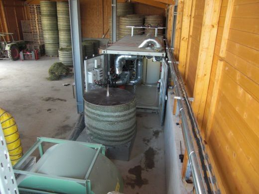
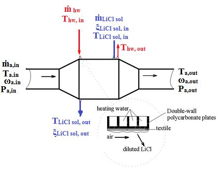
The basic concept of liquid desiccant
dehumidification system is to directly
reduce the moisture and warm up the air,
which is used for drying, only a few
degrees above the ambient temperature.
In the absorber, moisture absorbed from
the process air stream dilutes the
desiccant solution by loading the
desiccant with water vapour (Fig. 1).
Fig. 1: Schematic of the liquid desiccant system.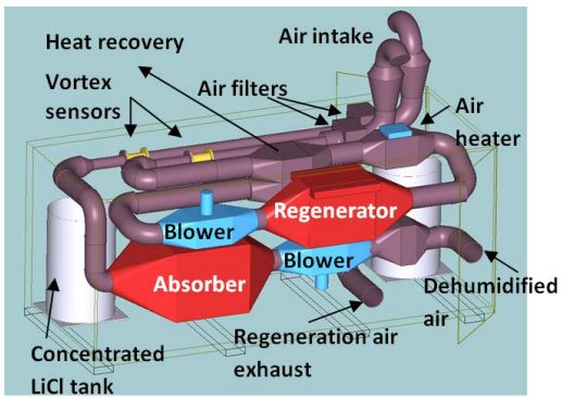
The solution weakened by absorption of moisture is re-concentrated in the
regenerator, where it is heated to elevate its water vapour pressure. The heat drives
out the moisture from the solution and the strengthened solution is returned to the
dehumidifier. A scavenging air stream contacts the heated solution in the
regenerator. There, water evaporates from the desiccant solution into the air and the
solution is re-concentrated.

2. Experimental Setup
Experiments were conducted to measure the moisture transfer as well as the
temperature difference during the absorption and desorption processes. In all the
absorber and regenerator prototypes used, the air stream and the LiCl-H2O solution
are set up in a cross flow configuration. Textile fibers are used in order to increase
the exposure time of the desiccant and thereby enhance the desired mass transfer
and heat exchange. The distribution system of the sorbent uses Plexiglas tubes to
horizontally distribute the solution over the textile. The tubes penetrate the absorber
or regenerator horizontally and spread the desiccant solution over the coated plates
or tubes through a number of equally spaced holes. The size and number of the
holes are selected according to distribution tests carried out in [2] to provide the
desired liquid flow. The LiCl-H2O solution flows through the distribution system, it is
then throttled over the textile and trickles down along the plates or tubes by gravity.
Lithium chloride is used as the liquid desiccant because of its favorable physical
properties [3].
2.1. Laboratory Pilot Plant
The overall exposed surface area of a small laboratory prototype used as absorber
and regenerator, is about 3.9 m2. The heat and mass exchanger consists of a stack
twin wall polycarbonate plates.

           Fig. 2 Schematic diagram of the experimental setup, pilot plant stage
The air is conditioned according to the required set-value with a series of instruments
(electric air heater, air cooler/dehumidifier, steam generator). For monitoring of the
air, a vortex flow meter, and HygroFlex humidity and temperature transmitters are
used at the inlet and outlet of the component. The density and the temperature of the
LiCl-H2O solution are monitored before and after the heat and mass exchanger, the
flow rate is measured with a magneto-inductive flow meter. All values were
continually monitored during the experiments.

2.2. Demonstration Plant for Drying Hay Bales
The desiccant absorber in the demonstration plant consists of a plate type heat and
mass exchanger with a total exposed surface of about 75 m2. The dried and heated
air is blown through a hose to a wide air channel with a circular opening for one hay
bale. The desiccant regeneration system consists of a heat and mass exchanger
made of copper pipes, protected from corrosion with a thin powder coating layer.
Textile sleeves are applied over the copper tubes. The total exposed surface area of
the regenerator is about 9 m2. Hot water supplied by solar collectors flows through
the copper tubes to heat the desiccant solution in order to concentrate it again.

                                                     Demonstration plant during installations
Schematic diagram of the exp. setup

                                               2
Construction of the solar collector field (155m ),   The drying-sorption plant connected to the hay
April 2012                                           bale, July 2013
                  Fig. 3: Demonstration plant in Frankenhausen (near Kassel)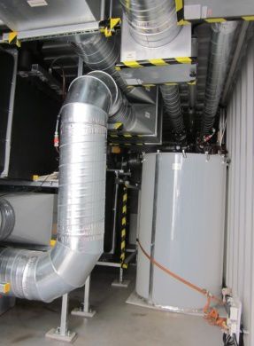
3. Inlet Values for Laboratory Experiments
The prototype was tested in an adiabatic dehumidifier mode. 12 experimental runs
were conducted in three experimental sequences.
Table 1: Inlet conditions for the laboratory tests in dehumidification mode (absorption)
. , ,
kg/h ºC g/kg
Test seq.1 var:14.1-56.3 24.6 ± 0.1 14.36 ± 0.27
Test seq.2 14.2 ± 0.63 var:24.5-30.1 14.69 ± 0.21
Test seq.3 44 ±0.54 25.3 ± 0.2 var:13.64-20.20
The air mass flow rate was kept constant of 375 kg/h ± 4 kg/h, desiccant inlet
temperature of 27 ºC ± 1.1 ºC and desiccant mass fraction (ξ) of 0.43 kg/kg.
Moreover, the prototype was tested in a non-adiabatic regenerator mode by using hot
air and water streams. Six experimental runs were conducted in two experimental
sequences. The air mass flow rate was kept constant of 302 kg/h ± 4 kg/h, desiccant
inlet temperature of 27 ºC ± 1.1 ºC, inlet heating-water temperature of 50.3 °C and
desiccant mass fraction of 0.36 kg/kg, while varying the air humidity ratio and the
desiccant mass flow rate.
4. Results and Discussion
4.1. Laboratory Experiments of a Small Heat and Mass Exchanger
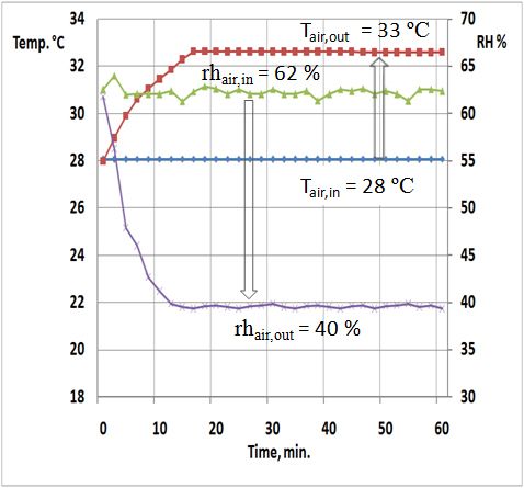
The results of the supply air
adiabatic dehumidification show a
consistent reduction in the relative
humidity, a consistent reduction in
the humidity ratio, and an
increase in the air temperature.
Figure 4 shows an example of
one of the experiments; the
change in the relative humidity
reaches about 42 percent-points
and an increase in the air Fig. 4: Example measurement: Dehumidification in a small
temperature of about 5.2 K. laboratory prototype.
The mass transfer performance of the dehumidifier was evaluated in terms of the
moisture removal rate. The moisture removal rate, ṁv, is calculated by Eq. 1 [4].
= ∙ , − , Eq.1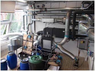
Moisture removal rate , g/s

                                                                              Moisture removal rate, g/s
                                0,5                                                                        0,6

                               0,45                                                                        0,5
                                0,4                                                                        0,4
                               0,35
                                                                                                           0,3
                                0,3
                                                                                                           0,2
                               0,25
                                                                                                           0,1
                                0,2
                                                                                                            0
                               0,15
                                                                                                                 12       14        16            18        20   22
                                      0       5         10         15    20
                                                                                                                           Inlet air humidity ratio, g/kg
                                          LiCl-H2O mass flow rate, g/s
                                                                                                                  Experimental       F.D. Model

Fig. 5: the moisture removal rate as a function of desiccant flow rate and air inlet humidity
ratio for the dehumidification experiments.

As shown in Figure 5, the moisture removal rate in both directions increased
remarkably with increasing desiccant flow rate for both of absorption and
regeneration systems. The moisture removal rate increases with increasing the air
inlet humidity ratio in the absorber and vice versa for regeneration.
The effect on the moisture removal rate was caused by the increased average water
vapor pressure difference between the air and the desiccant with increasing air inlet
humidity ratio.
The experimental results were compared with an ideal numerical finite difference
model. In Figure 5, the blue points represent the experimental results and the red
points represent the finite difference results. The comparison between the
experimental and numerical results shows divergences, both, due to uncertainties of
experimental data and due to idealized assumptions of the numerical model. A more
detailed analysis of the deviations will be carried out in future investigations.

4.2. First Experimental Results of the Demonstration Plant
Table 2: Initial measurements from the demonstration plant for a drying experiment of a hay
bale.

5. Conclusions
Plate and tube bundles type heat and mass exchangers were built and tested in a
pilot plant stage and in a demonstration plant as an air dehumidifier and desiccant
regenerator.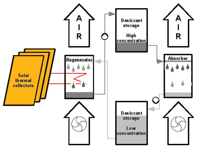
Parameter variations were carried out in the laboratory. The experimental results of a
small laboratory prototype show a reduction in the supply air humidity ratio in the
absorption process of about 4.8 g/kg for typical reference conditions. The results
show a consistent reduction in the relative humidity and an increase in the air
temperature, which are the main factors that affect how readily moisture moves from
the drying product. The parametric analysis results in reduction of the air relative
humidity in the range of 18-46% points and an increase in the air temperature in the
range of 3.7-8.0 K are observed, depending on the inlet parameters. The mass
fraction of the diluted desiccant solution (from 0.38 to 0.43 kg/kg) was possible by
using hot water of 55-60ºC.
The results were analyzed and compared with results from a finite difference model.
In a demonstration plant, first measurements showed promising results of the
dehumidification of hay bales. The drying time for a hay bale could be reduced
significantly. The air stream temperature was increased by more than 10 K while
relative humidity was reduced by more than 40%-points during the tests.

Acknowledgements
This research project is supported by the German Federal Ministry for Education and
Research in the framework of the research program “KLIMZUG Nordhessen –
Climate Change in Regions”.

References
[1] Gunasekaran, S., “Optimal energy management in grain drying”, CRC Critical
Reviews in Food Science and Nutrition, Vol. 25 Issue 1, pp. 1-48, 1986.
[2] Jaradat, M., Heinzen, R., Jordan, U., Vajen, K., A Novel Generator Design for a
Liquid Desiccant Air Conditioning System, Proceedings of the EuroSun 2008
Conference, Lisbon (PO), 07.10 - 10.10.2008.
[3] Conde, M.R. “Properties of aqueous solutions of lithium and calcium chlorides:
formulations for use in air conditioning equipment design”, International Journal of
Thermal Sciences, vol. 43,pp 367–382.
[4] Lävemann, E. Peltzer, M. ,Solar Air Conditioning of an Office Building in
Singapore Using Open Cycle Liquid Desiccant Technology, Proceedings of the
International Conference on Solar Air Conditioning, Staffelstein (DE), 06.-07.10.2005.
You can also read