Vacuum Traps - Solberg Manufacturing
←
→
Page content transcription
If your browser does not render page correctly, please read the page content below
SOLBERG
®
®
Filtration • Separation• Silencing
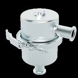
Vacuum Traps
VTL / VTS Series NW16 - NW50
Overview
Solberg’s vacuum traps can be used to protect a variety of
vacuum pump technologies from particulate, liquid, aerosol
and vapour contaminants migrating from a process. Multiple
insert options and configurations are available to ensure
pumps are properly protected. The trap minimizes pump oil
contamination resulting in significantly fewer oil changeouts
and reduced maintenance costs.
Benefits
■ Prevent back streaming
■ Remove hydrocarbons
■ Trap condensable vapours
■ Reduce overall maintenance costs
■ Chemical resistant VTL Series
■ Easy maintenance
Features
■ All stainless steel construction
■ No tools needed to separate housing hemispheres with
the quick release v-band for ease of maintenance
■ Integrated drain port
■ Connections available NW16, 25, 40, 50
Technical Specifications
■ Vacuum service down to 1x10⁻³ mbar
■ Leak rate: 1x10⁻⁷ mbar L/sec
■ Temperature range -20°C to 150°C
■ Fine bead blast finish
■ Viton O-ring
VTS Series
www.solbergmfg.com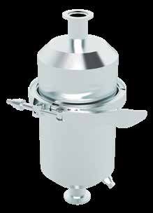
Standard Configurations:
 Stainless Steel Metal Wool                                                                                             A
  ■ Trap hydrocarbons and large particulate
  ■ Replaceable stainless steel or copper insert
                                                                                                                                                D
  ■ Reduce contamination

 Molecular Sieve
  ■ Trap water vapour and other gases                                                        C
  ■ Rechargeable 13X Zeolite desiccant
  ■ Integral 120 VAC or 240 VAC regeneration heater
  ■ Reduce oil change-out

 Options (contact factory):
                                                                                                                         B

 Chemical Adsorbents                                                                                                          E

  ■ Trap chemicals and corrosives
  ■ Chemical compatible adsorbents available                                                              VTL Configuration
    (ie: activated carbon, alumina, SodaSorb, etc.)
  ■ Reduce hazards

 Fine Particulate
                                                                                                                          A
  ■ Trap fine particulate
  ■ Multiple media available (down to .2 micron at
    99.99% efficiency)
  ■ Reduce dust and particle ingestion

                                                            Dimensions - mm
        Assembly           VTL Housing
       Part Number             Size           A         B          C        D           E
                                                                                                      C
   VTL-SSM4-NW16S1              4”           102       133          191    38       168
   VTL-SSM4-NW25S1              4”           102       133          191    38       168
   VTL-SSM6-NW40S1              6”           155       183          248    64       211
   VTL-MS4-NW25S1               4”           102       133          191    38       168
   VTL-MS4-NW40S1               4”           102       133          191    38       168
   VTL-MS6-NW50S1               6”           155       183          248    64       211

                                                      Dimensions - mm
                                                                                                                         B
        Assembly           VTS Housing
       Part Number             Size               A          B             C

   VTS-SSM4-NW16S1              4”             102            135         286
                                                                                                           VTS Configuration
   VTS-SSM4-NW25S1              4”             102            135         286
   VTS-SSM6-NW40S1              6”             155            183         286

   NOTE : When unable to achieve base pressure, the operator should regenerate the sieve by turning on the heater for a few hours and running the
   mechanical pump with its ballast valve open. The frequency and duration of sieve regeneration depends on the kind and amount of gas(es) produced by
   the particular application.

                                                                                                                             SOLBERG
                                                                                                                             SOLBERG
                                                                                                                                                         ®

All model offerings and design parameters are subject to change without prior notice.                                    ®
                                                                                                                             Filtra�on & Separa�on
Contact your representative or Solberg for the most current information.
SOLBERG
®
®
Filtration • Separation• Silencing
Technical Data
Inlet Vacuum Filters
Applications & Equipment Identification
■ Industrial & Severe Duty Standard Solberg assemblies should have an identification
■ Vacuum Pumps & Systems: Roots, Rotary label/nameplate that gives the following information:
Vane, Screw, Piston ■ Assembly Model #
■ Vacuum Packaging Equipment ■ Replacement Element #
■ Vacuum Furnace The part number designates the filter type, the element
■ Blowers: Side Channel & P.D. configuration and housing connection size. For example, the
■ Vacuum Lifters following part number identifies the filter as being a “CSL”
■ Intake Suction Filters design filter with a “235™” element, “P” prefilter and DN100
flange connection size.
■ Food Industry
■ Woodworking/Routers
■ Ash Handling CSL-235P-DN100
■ Printing Industry
■ Medical/Hospital Connection Size and Type
■ Sterilization Replacement Element Part Number
■ Remote Installations for Piston & Screw Filter Type
Compressors
■ Paper Processing
■ Waste Water Aeration
■ Cement Processing
■ Bag House Systems
Vacuum Service Rating Chart
■ Vacuum Vent Breathers Threaded vacuum filter connections must be free of defect
■ Chemical Processing and properly sealed to achieve deeper vacuum levels.
Vacuum service levels are given for reference only and serve
■ Factory Automation Equipment
as a guideline for product selection. Product certification and
■ Leak Detection Systems
alternative designs are available for applications requiring
■ Semiconductor / Solar deeper vacuum levels and specific leak rates. Please contact
factory for details.
Vacuum Level Pressure (mbar) Pressure (Torr) Pressure (Pa)
Atmospheric Pressure 1013 760 1.013x10+5
Rough Vacuum 1013 to 33 760 to 25 1x10+5 to 3x10+3
Medium Vacuum 33 to 1.3x10⁻³ 25 to 1x10⁻³ 3x10+3 to 1x10⁻¹
High Vacuum 1.3x10⁻³ to 1.3x10⁻⁹ 1x10⁻³ to 1x10⁻⁹ 1x10⁻¹ to 1x10⁻⁷
www.solbergmfg.comChoosing the Best Filter for Your Equipment
A. When the connection & airflow is known:
1. Select the appropriate connection style. (i.e.: BSPT, Flange, BSPP, etc.)
a. Verify assembly m3/hr (flow) rating. Compare with your required airflow.
(Note: Assembly flow ratings are based on 6,000 FPM or 30m/sec for a given connection size to achieve low
pressure drop performance. When required flow exceeds assembly flow rating, the pressure drop through the
outlet connection will increase. In such cases select by element m3/hr (flow) rating.)
b. Verify that the flow rating matches connection size; skip to “C. Selecting Elements”.
B. When the connection size is unknown, flexible, or the required flow rating exceeds assembly flow rating:
1. Match required flow rating with the element flow rating.
2. Choose related connection size.
C. Selecting Elements: The filter performance is influenced by the actual application duty and the equipment it is installed on.
Regular maintenance checks and proper servicing is required.
Application Duty Descriptions:
Industrial Duty: clean workshop or clean outdoor environment ‐ small element sizing is sufficient.
Severe Duty: dirty workshop, wastewater – medium to large element is recommended.
Extreme Duty: cement, steel making, plastics or dusty material conveying – largest element sizing is recommended.
1. Select media required by your application. Options include:
a. Standard media
1. Polyester: all purpose; withstands pulses, moisture, and oily air
2. Paper: mostly dry, smooth flow applications
b. Special Media: for a variety of micron levels and media types, see the “Filter Media Specifications” in the
Replacement Element Section or contact Solberg.
2. Select element size by matching the element with the anticipated duty and upsize accordingly.
Filter Assembly Maintenance
Request the appropriate maintenance manual for more in‐depth information from your Solberg representative or on our
website: www.solbergmfg.com.
Element Maintenance
Solberg elements should be replaced once the pressure drop reaches 37-50 mbar above the initial pressure drop of the
installation. Cleaning the element is also an option.
Solberg recommends replacing dirty elements for optimal performance. Any damage which results from by‐pass or additional
pressure drop created by element cleaning is the sole responsibility of the operator.
Note: The overall performance of a filter element is altered once cleaned. The initial pressure drop after subsequent cleanings
will be greater than the original, clean pressure drop of the element. After each cleaning, the pressure drop will continue to
increase. Under all circumstances, the initial pressure drop of the element needs to be maintained at less than 37 mbar.
If the pressure drop exceeds 50 mbar at start‐up; it should be replaced with a new element. With many types of equipment,
the maximum pressure drop allowed will be dictated by the ability of the equipment to perform to its rated capacity. Under
all circumstances, the operator should avoid exceeding the manufacturer’s recommended maximum pressure drop for their
specific equipment.
SOLBERG
SOLBERG
®
All model offerings and design parameters are subject to change without prior notice. ®
Filtra�on & Separa�on
Contact your representative or Solberg for the most current information.You can also read