Technical Guide - Bender + Wirth
←
→
Page content transcription
If your browser does not render page correctly, please read the page content below
Technical Guide
For:
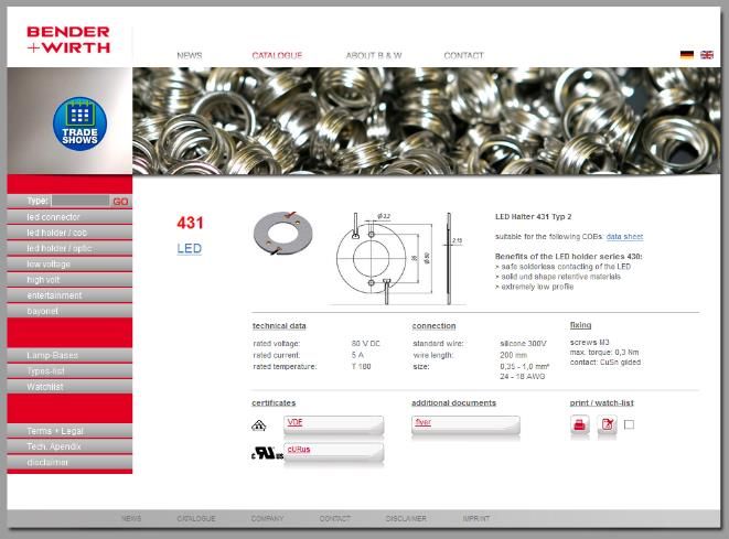
LED Holder Series 430
Release:
01.10
Release-Date:
2018-09-21
Please take note of the following instructions for the selection and assembling of the
B+W LED Holder Series 430.
The information in this document is provided without liability and subject to change without notice.
© BENDER + WIRTH GMBH & CO.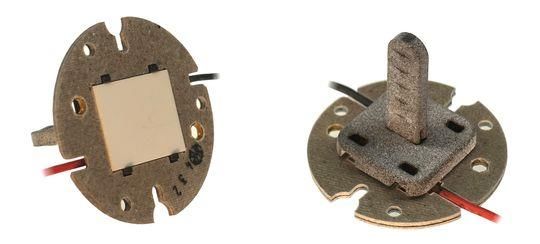
TECHNICAL GUIDE
LED HOLDER SERIES 430

1.      Scope
The B+W LED Holder Series 430 offers a wide range of different standard COB holders
together with the option to realize nearly unlimited customized versions.
This technical guide incorporates all important aspects of handling and assembling our holders
appropriately and explains our encoding system.
Our customer service team will help you to identify (or create) the best solution for your
application. Please feel free to contact us for any further questions or demands.

2.      Safety instructions
B+W LED holders are designed for an optimal fixation of Chip on Board (COB) LED´s. For the
correct operation, handling, thermal management and electrical connection you have to follow
the COB manufacturer’s instructions.
The holder is part of an electrical circuit, therefore only trained personnel should handle them.

3.      Certificates
The complete B+W LED Holder Series 430
including all customized versions is certified
according to:
                UL 8754
                CAN/ULC-S8754
                DIN EN 60838-1

The original certificates of compliances are
downloadable from our online catalogue.
                VDE Certificate No. 40041342
                UL- File E472943

© BENDER + WIRTH GMBH & CO.    RELEASE: 01.10 | RELEASE-DATE: 2018-09-21 | PRINT-DATE: 2018-09-21   PAGE 1 OF 9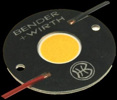
TECHNICAL GUIDE
LED HOLDER SERIES 430

4.      Encoding system
B+W developed a vast amount of customized holder versions, alongside a range of about 400
standard holders. This chapter will explain the encoding system and how to differentiate the
holders.

4.1 Codes

Part No.                 XXXXX

Drawing No.              XXX           /              XXXXX                -        X
                              Article No.                          Part No.               Index

Description              LED Holder           XXX                                Type XX                 HV
                                                     Article No.                                 Type         High Voltage

4.2 Part Number / Teilenummer

XXXXX
The part number is the legal order code. You find it on every offer, order acknowledgement
and invoice in the first row.

4.3 Drawing Number / Zeichnungsnummer

XXX / XXXXX – X
Each part number has an individual drawing number (1:1 relationship). It contains the article
number, the part number itself and optionally an index. You find it on every offer, order
acknowledgement and invoice in the second row (and, of course, on every drawing).

4.4 Article Number / Artikelnummer

XXX
The article number designates which COB is suitable for the
selected holder. You find it within the drawing number and
within the description.
Important dimensions are the outside dimensions, the
acceptable thickness of the COB´s and specific contact point
positions (see yellow marked area on the bottom view picture).
Currently available versions are listed in our online catalogue.                                          Bottom view

© BENDER + WIRTH GMBH & CO.         RELEASE: 01.10 | RELEASE-DATE: 2018-09-21 | PRINT-DATE: 2018-09-21                 PAGE 2 OF 9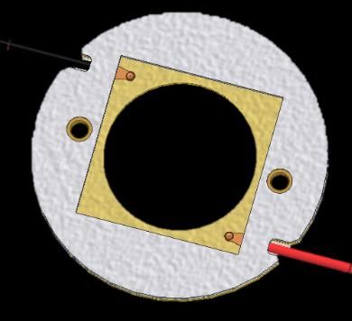
TECHNICAL GUIDE
LED HOLDER SERIES 430

4.5 Description / Beschreibung

LED Holder XXX Type XX HV
You find the description on every offer, order acknowledgement and invoice in the third row. It
contains the article number, the type and optionally the high voltage mark.

4.5.1 Article Number / Artikelnummer

LED Holder XXX Type XX HV
See above (chapter 4.4)

4.5.2 Type / Typ

LED Holder XXX Type XX HV
The type defines shape and fixing points of a holder (see yellow marked area on the top view
picture). Types can be classified by a single number, by a letter and a single number or by a
letter and two numbers:

Type 1, 2, 3, 4 …
                holder without specific optical interface

Type A1, K1, L5 …
                holder designed for optical or thermal systems
                                                                                                      Top view
HV
                Holders marked with "HV" are appropriate for high voltage up to 450V DC.
                Specification is shown on the drawing.

© BENDER + WIRTH GMBH & CO.      RELEASE: 01.10 | RELEASE-DATE: 2018-09-21 | PRINT-DATE: 2018-09-21              PAGE 3 OF 9
TECHNICAL GUIDE
LED HOLDER SERIES 430

5.      Handling
Most of our holders are equipped with wires which are welded to the contacts.
                Please avoid mechanical stress onto the wires or contacts (for e.g. pushing or
                pulling of the wires) during unpacking or assembling.
                The holders should stay within the original package in a dry and tempered
                location until assembling.
Of course all handling instructions of the COB supplier have to be followed as well.

6.      Assembly instructions
Due to the high performance material B+W LED Holders create a constant pressure onto the
COB, even at high temperatures where other materials yield. This ensures a minimal thermal
resistance.

6.1 Thermal Interface Material (TIM)

The additional use of a Thermal Interface Material (TIM) reduces the thermal resistance.
B+W LED Holders can be used with the following TIM´s:
                Paste (must be applied finely)
                Graphite pads
                Silicon pads (mostly used for insulated applications / HV versions)
                Phase change material (must be very thin to get the optimal performance)

The optimal thermal functionality always depends on different parameters. The component
combination should be tested with cautiousness.

6.2 Assembly

6.2.1 Flipped / Upside Down Assembly

Standard B+W LED holders provide no clipping mechanic for COB modules, therefore a flipped
/ upside down assembly is recommended. It differs slightly depending on the chosen thermal
interface material.

© BENDER + WIRTH GMBH & CO.     RELEASE: 01.10 | RELEASE-DATE: 2018-09-21 | PRINT-DATE: 2018-09-21   PAGE 4 OF 9
TECHNICAL GUIDE
LED HOLDER SERIES 430
use a simple pilot tool
size and design depends on your application
Step 1
set our holder on the pilot tool
Step 2
put the LED in the holder, note the polarity
Step 3
place the TIM
(with self-sticking TIM, the package can be removed from
the pilot tool after this step)
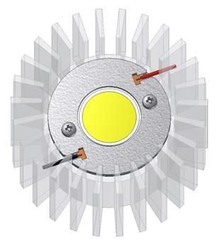
Step 4
set the heat sink on top
Step 5
keep pilot tool and heatsink together and flip the
complete package upside down
Step 6
just remove pilot tool and install the screws to complete
the assembling
max torque is 0,3Nm
© BENDER + WIRTH GMBH & CO. RELEASE: 01.10 | RELEASE-DATE: 2018-09-21 | PRINT-DATE: 2018-09-21 PAGE 5 OF 9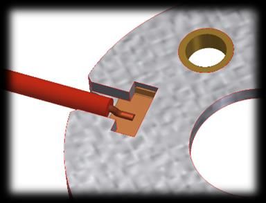
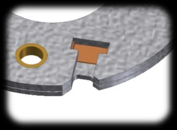
TECHNICAL GUIDE
LED HOLDER SERIES 430

6.2.2 Assembly via Clip-In Function

The new COB Clip-In function was presented at this year´s Light + Building for the first time.
The operating principle is very simple: The Clip-In tool has small extensions on the bottom,
which grab through fitting holes in the holder. Now, the COB can be fixed between these
extensions. As soon as the holder is screwed down onto the heat sink, the tool releases again.

As of now, the Clip-In function is available for all COB holders from Bender + Wirth. It simplifies
the assembly of luminaires and light engines a lot. The assembly tool shown here has a handle
to further simplify the positioning.
If you are interested in this assembly method, please don´t hesitate to contact us.

© BENDER + WIRTH GMBH & CO.   RELEASE: 01.10 | RELEASE-DATE: 2018-09-21 | PRINT-DATE: 2018-09-21   PAGE 6 OF 9
TECHNICAL GUIDE
LED HOLDER SERIES 430

6.3 Fixing screws

The standard holders are equipped with flat rivets. Do only use screws with a flat inner face.
Do not use screws with a conical / tapering inner face. They can damage the flat rivet:

Flat (standard) rivet

As an option there are different special rivets available where conical screws can be used:

Round-head rivet

                                                     B+W 45634

The special counter-sunk screw B+W 45634 has a very small head diameter to minimize the
total height.

The maximum fixing torque for all screws is 0,3 Nm. We recommend to use a torque screw
driver to ensure the correct fixing.

© BENDER + WIRTH GMBH & CO.   RELEASE: 01.10 | RELEASE-DATE: 2018-09-21 | PRINT-DATE: 2018-09-21   PAGE 7 OF 9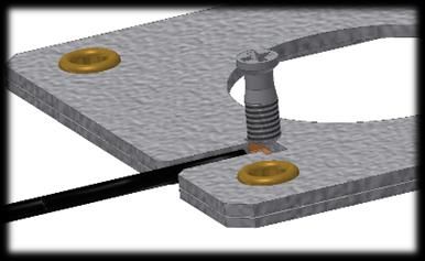
TECHNICAL GUIDE
LED HOLDER SERIES 430

7.      Electrical Connection

7.1 Contacts

The contacts are made of CuSn with gilded contact areas.

7.2 Contact pads of the COB

For the best performance the contact pads at the COBs must be gilded. Tinned contact pads
are not acceptable due to possible oxidation.

7.3 Connection leads

Most of our holders are delivered with connection leads.
The wires are welded to the contacts for the optimal electrical
performance and best mechanical fixing.
The standard wires are listed on the next page. The wires are UL
and VDE certified.

7.4 Wire ends

The standard holder version includes semi stripped wire ends. Other options are available on
request.

7.5 Solder connection

Optionally, the holders can be manufactured without wires, but with
installed blank contacts. You can solder your specific wire onto the
contact by not exceeding 450°C / 3s with a standard soldering device.
The soldering process should be finished before assembling the COB
to avoid any overheating of the COB.

© BENDER + WIRTH GMBH & CO.   RELEASE: 01.10 | RELEASE-DATE: 2018-09-21 | PRINT-DATE: 2018-09-21   PAGE 8 OF 9
TECHNICAL GUIDE
LED HOLDER SERIES 430

8.      Technical details and standard ratings

rated voltage:                                           80 V DC (optionally 150 to 450V DC)
rated current:                                           5A
rated operating temperature:                             T180

standard connection leads:                               SiF 0,35 mm²/AWG 22, 300V 150°C
                                                         SiF 0,5 mm²/AWG 20, 300V 150°C
                                                         SiF 1,0 mm²/AWG 18, 300V 150°C
                                                         PVC 0,35 mm²/AWG 22, 300V 105°C

fixing:                                                  screw M3
max. torque:                                             0,3 Nm

material:                                                mica
contact material:                                        CuSn gilded

9.      Disclaimer
This technical guide was created to provide guidance in customer applications for the LED
holder series 430 of Bender + Wirth. Bender + Wirth assumes no responsibility regarding the
completeness and accuracy of the contents, as well as the suitability of the systems for a
particular purpose.
Bender + Wirth is in no way liable to third parties for direct or indirect consequential damages
arising directly or indirectly from the use of this document.
It is the responsibility of the customer to ensure that the design meets all the necessary
requirements and safety certifications that are needed for its intended use.

10. Contact
Bender + Wirth GmbH & Co                   Phone: +49 (0) 2359 / 669 - 0                       Mail: info@bender-wirth.de
Volmestr. 161 | D-58566 Kierspe            Fax:      +49 (0) 2359 / 669 -186                   Web: www.bender-wirth.de

© BENDER + WIRTH GMBH & CO.       RELEASE: 01.10 | RELEASE-DATE: 2018-09-21 | PRINT-DATE: 2018-09-21                   PAGE 9 OF 9
You can also read