RW Audio Amp1 DIY Assembly Guide
←
→
Page content transcription
If your browser does not render page correctly, please read the page content below
RW Audio Amp1 DIY Assembly Guide
                                         Rev. 1.0 October 9, 2009

1. Check all items against BOM to ensure there are no missing parts.
2. Gather the required tools for assembly and testing.
       a. Soldering iron & solder.
       b. Side cutter for trimming component leads.
       c. Allen keys 0.050”, 1/16” (included) & 6mm (not included).
       d. Hobby knife to trim LED holder.
       e. Cheap headphones for testing (dollar store variety).
3. Look over the entire assembly process to familiarize yourself with the steps BEFORE starting.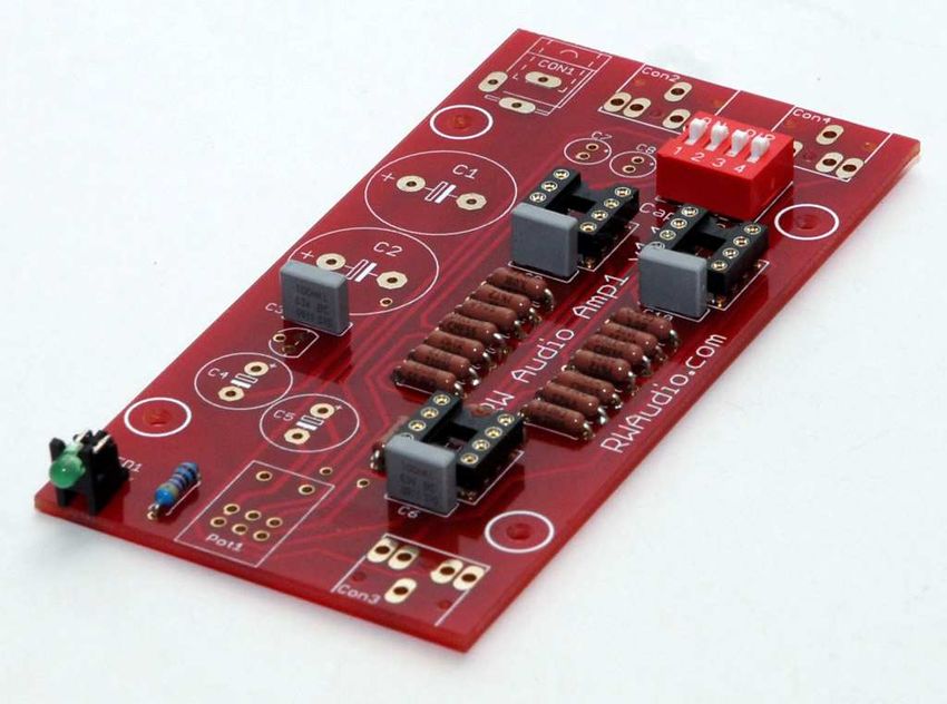
Bill of Materials (BOM)
            PCB Parts                     Description                             Qty
Amp1 PCB                               Amp1 V1.1 Red PCB                           1
R1, R2                           1.1K Ω RESISTOR VISHAY/DALE                       2
R3, R3L, R5, R5L, R6, R6L       3.01K Ω RESISTOR VISHAY/DALE                       6
R4, R4L                         100K Ω RESISTOR VISHAY/DALE                        2
R7, R7L                          10K Ω RESISTOR VISHAY/DALE                        2
R8, R8L, R9, R9L                 100 Ω RESISTOR VISHAY/DALE                        4
RLED                                    4.xK Ω METAL FILM                          1
Dip1-Dip3 (IC2 – IC4 on PCB)               8 Pin Dip socket                        3
C3, C6, C9, C10                            0.1uF/63V MKT                           4
SW1                                   Gain/input cap switch(top)                   1
LED1                                  LED Green 3mm diffused                       1
Con1                                         Power plug                            1
Con2 – Con4                            3.5mm headphone jack                        3
Pot1                                10K Ω Stereo Pot with Switch                   1
IC1                                   TLE2426CLP Rail Splitter                     1
C7, C8                                    10uF/25V Silmic II                       2
C1, C2                               1800uF/25V Panasonic FM                       2
C4, C5                                 100uF/25-35V Silmic II                      2
IC2                                            LM6171                              1
IC3, IC4                        LME49860(Optional LME49720HA)                      2
            Hardware
4-40 x 3/8” Screw                 Board/Foot mounting hardware                     8
1/8” Nylon Spacer                   Board mounting hardware                        4
#4 Lock Washer                      Board mounting hardware                        4
4-40 Nut                            Board mounting hardware                        4
4-40 x 1/4” Screw                  Top/Bottom panel hardware                       8
M8-1.25 x 12or16 Screw             Front/Back panel hardware                       4
Foot Retainer (square nut)          Foot mounting hardware                         4
Rubber Feet                              Foot protector                            4
4-40 Set Screw                           Knob hardware                             2
            Enclosure
Bottom Panel                            8 holes 0.050” thick                       1
Side Extrusions                        Left/Right side panels                      2
Top Panel                        4 holes w/Headphone logo 0.050”                   1
Back Panel                        Input/output/power logo 0.050”                   1
Front Panel                        RW Audio/Vol/Amp1 0.125”                        1
Aluminum Feet                      0.87” w/pocket for rubber foot                  4
Smooth Knob                                0.87” Smooth                            1
Knurled Knob                               0.87” Knurled                           1

        Power Supply
24v Regulated Wall Supply            Must be regulated 24v DC                      1

             Tools
1/16” Allen Key                   For all 4-40 button head screws                  1
0.050” Allen Key                         For knob set screw                        1

              Above items appear in the order of recommended assembly within each category.
PCB Assembly

1. Bend resistor leads 90° as shown for insertion into PCB. This Should be done one type at a time to avoid
   mixing up the values and placing a resistor in the wrong place by accident. These parts are non
   directional but must be installed in the correct location.

2. Install and solder resistors R1(L) – R9(L) and RLED, being careful to put the correct values in the correct
   places, match the value to the location using the BOM. This can be done one resistor at a time, or in
   groups of 2-6 for best results.

3. Install and Solder the chip sockets Dip1 – Dip3 onto the board in the IC2 – IC4 locations, the indent on
   the chip socket should match the indent shown on the board. By installing all of this type of part before
   soldering, the board will sit flat making the soldering process easier. This also helps the components sit
   flush and tight to the board. A piece of paper or card stock placed on top of the board works well to hold
   the parts in place while the board is flipped over for soldering.

4. Install and solder C3, C6, C9, C10. The same technique used above works well for these and any parts
   that are the same height.

5. Trim off the two plastic legs from the bottom of the LED holder. This allows the LED to sit flush on the
   PCB providing proper alignment with the front panel LED hole.
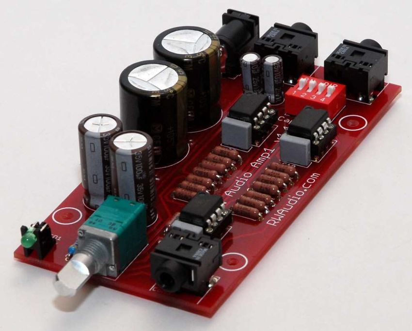
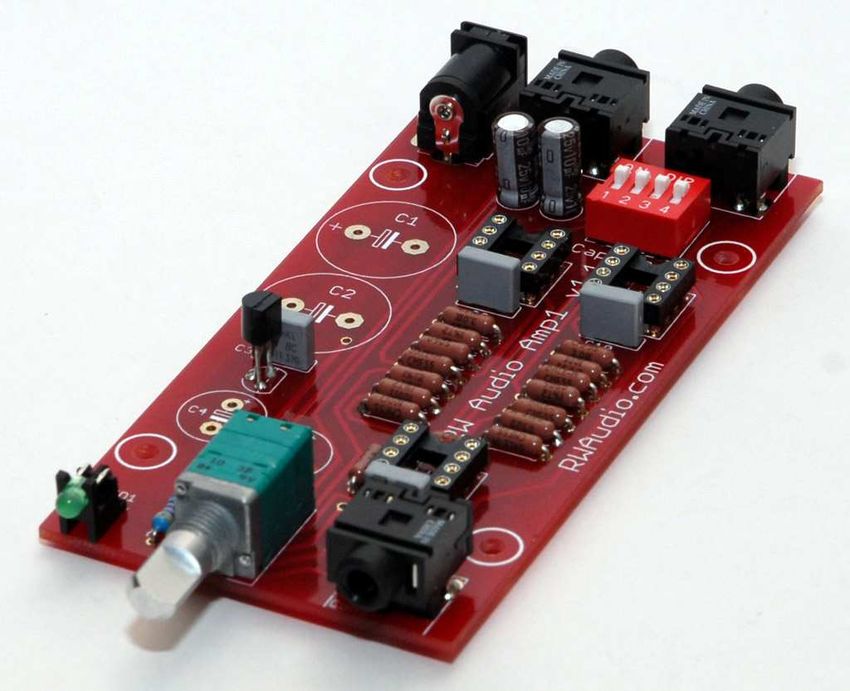
6. Install and Solder LED1 and SW1 to the board, both parts are directional and should be installed as
   shown below.

7. Install and solder Con1 - Con4, as well as Pot1. Some pins on Pot1 are close together, take care not to
   bridge any of these pins together when soldering. All of these parts are the same height and can be
   installed at the same time. It is a good idea to only solder one pad on each part at first, then when all of
   these parts are secure confirm that each part is straight and tight to the board. This is very important for
   proper fit to the front and rear panels.

8. Install and solder IC1, C7 and C8 (these are directional and must be installed as shown). IC1 should sit a
   short distance above the board and sit straight on the board, that way it doesn’t interfere with the
   capacitors on either side (IC1’s board label was mistakenly placed under C3, IC1 is between C3 and C4).
9. Install and Solder C1, C2, C4 and C5 (these are directional and must be installed as shown below).
Again all of these parts are the same height and if the opposite side of the board is temporarily supported
soldering will be easy.
10. Install IC2-4 in the dip sockets on the board. Be careful to install IC2 in the correct location at the front
of the board, IC3 and IC4 both use identical chips. Confirm switch settings all 4 switches should be “on”.
11. Double check the solder side of the board for any poor solder connections, solder bridges or parts not
properly soldered to the board and fix as required.
The PCB is now complete!
Take a break and give yourself a pat on the back.
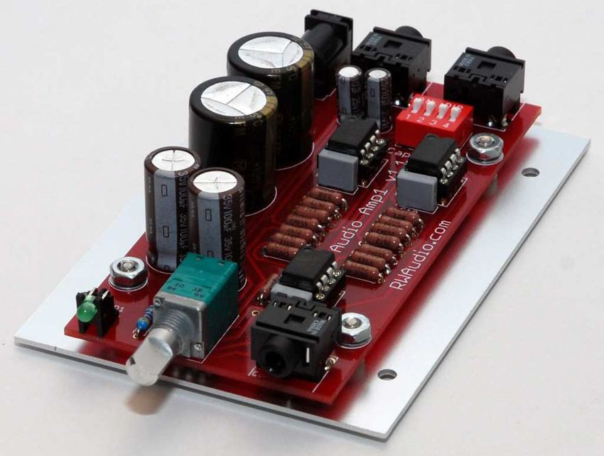
12. Prepare the bottom panel as shown below. Four 4-40x3/8” screws should be inserted through the inner 4
holes in the bottom panel. (Please note one side of the bottom panel may have a nicer appearance than
the other, the nicer side should face down).
13. Place the 1/8” spacers on the screws, this raises the board above the bottom plate to avoid any component
leads touching this panel and shorting out or causing undesired operation.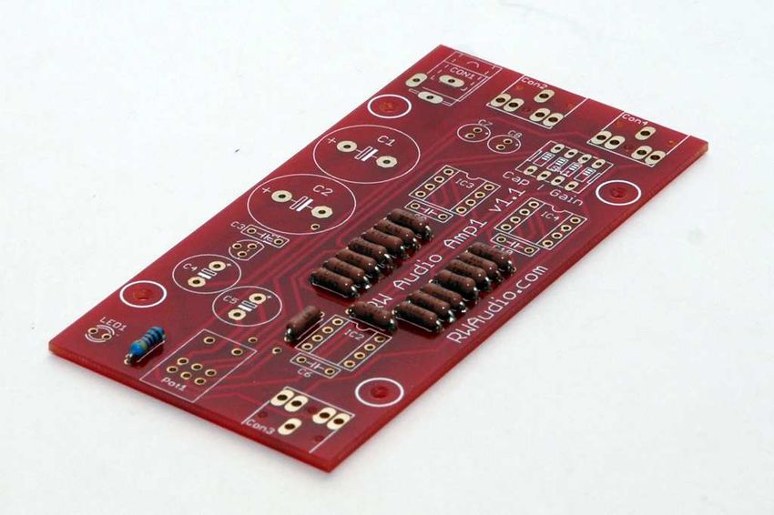
14. Test fit the board on top of the spacers, with the board fully supported by the spacers only there should be
    nothing touching the aluminum panel, fix/trim/resolder as required.

15. Place the lock washers and nuts on the screws protruding through the board. Do not over tighten! This
    will compress the 1/8” spacers and possibly short out the board, and miss align parts with the front/rear
    panel holes.

16. Place the two side panels about 2 inches apart and install four 4-40 x ¼” screws in the four outer holes
    securing the bottom panel to the sides. Do not fully tighten these screws as it will allow some adjustment
    room for the rest of the panels.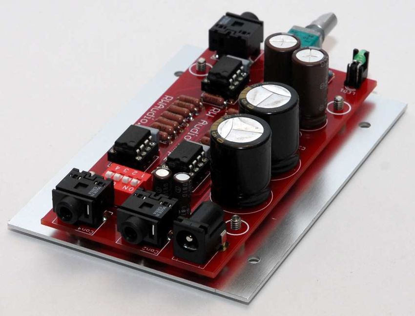
17. Flip the amp right side up and loosely install the top panel using the four remaining 4-40 x ¼” screws, do
    not tighten.

18. Install the back panel using two of the M8 screws, do not tighten.

19. Assemble the four amplifier feet as shown below, do not tighten! The square nut must be free to slide
    into the t-slot on the bottom of the amplifier.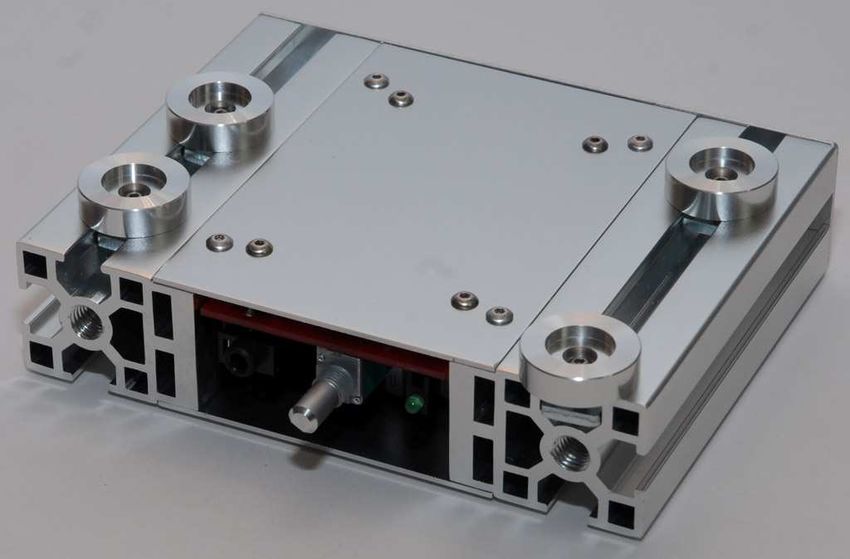
20. Slide two feet into each slot on the bottom of the amplifier, the screws can be tightened slightly but the
   feet should still move within the slot.

21. Install the front panel using the remaining two M8 screws. Tightening these screws should slightly
    recess the screw head into the pockets in the front panel as shown below. There should be no gaps around
    these screws and the screws should not sit on the outer face of the front panel, they should sink into the
    pockets.

22. Now tighten all of the remaining screws holding the panels together in the order: Top – Front – Bottom –
    Back. Do not over tighten the 4-40 Screws, not a lot of force is required to hold them securely. Damage
    to the screw or allen key may result.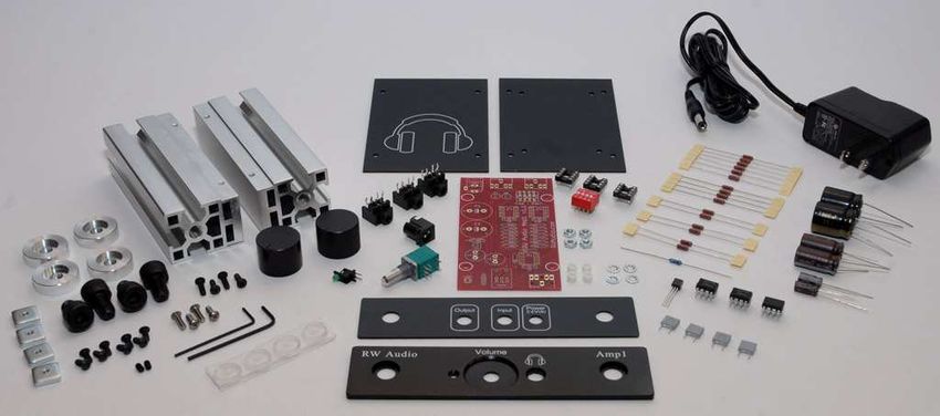
23. Move the feet to the desired locations, I suggest the front feet should rest flush up against the back of the
    front panel, and the back feet should sit on or just inside the back panel as shown above and below. After
    the screws are tightened peal off the rubber feet from the backing and install them into the recess in each
    foot. Turn the amp right side up and press firmly down on the amp for a few seconds to make sure the
    feet are properly seated.

24. Install the set screw in the volume knob, there are two knobs included in the kit allowing you to choose
   the look or feel you prefer. With the screw still loose install the knob on the shaft of the pot, the knob
   should not be pressed tight up against the face of the amp or the knob will bind when turning. Instead
   leave a small gap between the two allowing smooth operation.

                              The amplifier is now complete.
              Give yourself a pat on the back and prepare to test your creation.

25. Insert the power plug into the connector on the back of the amp. Plug the power supply into a suitable
    wall socket. Turn the volume knob clockwise to turn on the amp, the green LED should illuminate.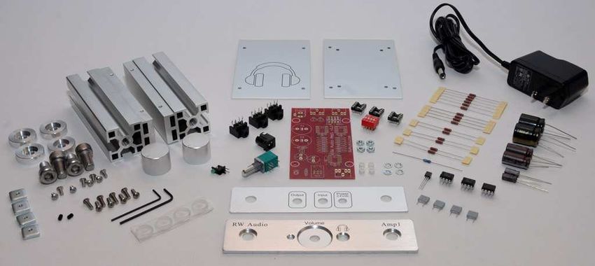
26. Connect a source to the input jack on the back of the amp. Connect some test headphones to the
    headphone jack on the front of the amp. Please do not use your $500 headphones for testing, most dollar
    stores have suitable ear buds that are great for amplifier testing.
27. RW Audio is not responsible for injury or damages caused by assembly or use of this kit. If you are not
    confident in your skills to properly assemble and test this amplifier please purchase the prebuilt version
    instead.
28. RW Audio is not responsible for injury or damages caused by assembly or use of this kit. If you are not
    confident in your skills to properly assemble and test this amplifier please purchase the prebuilt version
    instead. (listed twice to make sure you are paying attention).
29. If the test headphones sound good (as good as they can sound anyways) with no
    crackling/distortion/clicks/pops and the volume control operates correctly you are finished!
30. Connect your nice cans and enjoy your music of choice. Amp1 will sound good right away, but over 24-
    48 hours the amp will break in and sound even nicer. Amp1 can be left on 24/7 and draw minimal power
    (roughly 0.6 watts depending on configuration). After being turned off for a period of time Amp1 will
    sound better when it “warms up” for 15-30 minutes.

If you have any questions or concerns before, during, or after assembly feel free to
                        contact RW Audio for assistance.
                           Email: robin@rwaudio.com
                          MSN: rwaudio@hotmail.com
                              Phone: 403-277-1012
You can also read