A Neuromorphic Approach to Path Integration: a Head-Direction Spiking Neural Network with Vision-driven Reset
←
→
Page content transcription
If your browser does not render page correctly, please read the page content below
A Neuromorphic Approach to Path Integration: a
      Head-Direction Spiking Neural Network with
                  Vision-driven Reset
       Raphaela Kreiser∗‡ , Matteo Cartiglia∗‡ , Julien N.P. Martel∗† , Jörg Conradt† , and Yulia Sandamirskaya∗
     ∗ Institute   of Neuroinformatics, University of Zurich and ETH Zurich, Winterthurerstr. 190, 8057 Zurich, Switzerland
        † Neuroscientific   Systems Theory, Technical University of Munich, Karlstrasse 45-47, 80333 Munich, Germany
                                        ‡ These authors have contributed equally to this work.

                                            Email: {rakrei, ysandamirskaya}@ini.uzh.ch

    Abstract—Simultaneous localization and mapping (SLAM) is                      these neuronal circuits have been conducted [2], [3], however,
one of the core tasks of mobile autonomous robots. Looking                        emulating a neuronal architecture with its dynamics in software
for power efficient and embedded solutions for SLAM is an                         is computationally expensive and is therefore not suitable for
important challenge when building controllers for small and agile                 a real-time robotic application.
robots. Biological neural systems of even simple animals are
until now unprecedented in their ability to localize themselves                       Neuromorphic hardware, to the contrary, offers a physical
in an unknown environment. Neuromorphic engineering offers                        computational substrate for directly emulating the biophysics
ultra low-power and compact computing hardware, in which                          of neurons and synapses in real time [4]–[7], enabling low
biologically inspired neuronal architectures for SLAM can be                      latency through massively parallel, event-based computation.
realised. In this paper, we propose an on chip approach for one                   In robotics, analog neuromorphic hardware has proven itself
of the components of SLAM: path integration. Our solution takes                   capable to achieve better time complexity and power savings
inspiration from biology and uses motor command information
to estimate the orientation of an agent solely in a spiking neural
                                                                                  in path planning [8].
network. We realise this network on a neuromorphic device                             In this work, inspired by existing models of HD cells [2],
that implements artificial neurons and synapses with analog                       [3], we implement a HD network on a neuromorphic device.
electronics. The neural network receives visual input from an                     In our network, the recurrent connectivity in a population of
event-based camera and uses this information to correct the on-
                                                                                  HD neurons gives rise to a localized activity “bump”. Together
chip spiking neurons estimate of the robot’s orientation. This
system can be easily integrated with other localization and                       with an angular velocity input, this activity induces a shifted
mapping components on chip and is a step towards a fully                          localised “bump” in a second population of neurons, which
neuromorphic SLAM.                                                                feeds back into the HD population, making the activity bump
                                                                                  in this latter population move in the correct direction. Thus,
                        I.   I NTRODUCTION                                        the rotation of the robot shifts the HD activity according to the
                                                                                  robot’s angular velocity. In order to correct the accumulated
    Foraging in unknown, dynamically changing environments                        error that is due to device mismatch, as well as to odometric
is a crucial skill for the survival of every animal. One of the                   drift, a visual cue can reset the activity of the HD cells to the
tasks of foraging animals, as well as mobile robots, is to use                    correct location.
self-motion cues in order to compute the direction and distance
from the navigator’s current position to some reference point,                       We use the neuromorphic processor Reconfigurable On-
e.g. the nest. This process, called path integration, is prone                    Line Learning System (ROLLS) [9] that comprises hybrid
to accumulated error. In robots, this error is due to wheel                       analog/digital circuits to emulate the biological processes
slippage, uneven terrain, and sensor errors. In humans and                        of spiking neurons and synapses with ultra low-power (on
animals, drift in the estimated position occurs when navigating                   the order of 1mW). Thus, a neural network implementation
in the dark. In order to maintain an accurate position estimate,                  on neuromorphic hardware reduces dramatically the power
path integration can be corrected based on visual or other                        consumption for embedded systems that require real-time
external cues.                                                                    processing.
                                                                                      Similarly to biological neural networks that face the prob-
    Biological neural networks of even simple animals perform
                                                                                  lem of individual neurons and synapses being driven by
the task of path integration efficiently. Drawing inspiration
                                                                                  stochastic processes, neuromorphic silicon neurons are noisy
from these networks could therefore lead to particularly ef-
                                                                                  due to the variable nature of analog circuits and exhibit
ficient solutions in robotic navigation. A biological neural
                                                                                  mismatch due to fabrication imperfections. By functioning
network that plays a key role in spatial navigation is composed
                                                                                  in a robotic sensory loop, the proposed neural architecture
of orientation selective head direction (HD) neurons. HD
                                                                                  provides a sensory-motor embodiment and a functioning proof
neurons have been found in many animals and have been
                                                                                  of concept for existing models of biological HD cell networks.
referred to as a neural compass, as they spike in relation to
the orientation of the head with respect to the outside envi-                         We proceed with a brief introduction to the ROLLS neu-
ronment [1]. Contrary to a magnetic compass that can directly                     romorphic processor and the robotic agent that was used for
measure the orientation, neural circuits in the animal’s brain                    this work. We then introduce the proposed HD network and
compute the orientation based on internal motion cues and                         the visual reset mechanism. Finally, we validate the results of
external sensory input from the environment. Simulations of                       path integration using the IMU data as a ground truth.

      978-1-5386-4881-0/18/$31.00 ©2018 IEEE

         Authorized licensed use limited to: Stanford University. Downloaded on March 27,2021 at 00:32:30 UTC from IEEE Xplore. Restrictions apply.
II. M ATERIALS AND METHODS
The setup used in this work consists of the ROLLS
neuromorphic processor and the Pushbot robotic vehicle1 with
an embedded event based DVS camera (eDVS) [10]. Commu-
nication between the Pushbot and the ROLLS is coordinated by
a Parallella board [11]: the Pushbot communicates through a Pushbot and DVS
dedicated wireless connection to the Parallella board receiving
ROLLS Chip High frequency
motor commands and sending address-events produced by the Parallella LED
eDVS. The ROLLS chip is interfaced with the Parallella with
an embedded FPGA which is used to configure the network
connectivity and to stimulate neurons.
A. Neuromorphic processor
AER Input
Fig. 2: The pushbot with the eDVS (right), the ROLLS (left),
Synapse De-Multiplexer
and the visual beacon (center).
AER Output
AER Input
with two motors driving two independent tracks for propulsion
(left and right). It comprises an embedded dynamic vision
sensor (DVS) – an event-based camera, inspired by the mam-
malian retina [16], [17]. Each pixel of the DVS is sensitive
to the temporal change in luminance and sends out an event
non-plastic synapses virtual neurons
using the AER protocol. The robot has an integrated 9 DOF
synapses IMU which reports changes in velocity and orientation, which
is used here to obtain the ground truth of robot’s orientation.
Fig. 1: Block-diagram of the ROLLS chip architecture. The eDVS camera is configured to detect a high frequency
LED, filtering out the noise that arises from stochastic spiking
The ROLLS neuromorphic processor [9] is a full-custom and movement of the robot. A high frequency LED (3kHz) is
mixed signal analog/digital VLSI device. It comprises analog used as a visual landmark in order to reset the bump of activity
neuromorphic circuits that emulate the biophysics of spiking in the HD neural network. In our implementation, when the
neurons and dynamic synapses in real-time and asynchronous visual landmark is observed within a set area of the visual
digital circuits that manage the transmission and routing of array, the bump of activity is reset to the correct value.
spikes, using the Address Event Representation (AER) [12].
The chip comprises a column of 256 neurons, an array III. H EAD D IRECTION NETWORK
of 256x256 non-plastic programmable synapses, an array of In the past 20 years, HD cells have been characterized
256x256 plastic synapses, and 8x256 time-multiplexed “vir- biologically [1] and modeled extensively. An individual HD
tual” synapses that can be used to provide direct external input cell has a maximum firing rate at one particular orientation
to neurons. and its firing rate decreases monotonically moving away from
A block-diagram of the chip architecture is shown in Fig. 1. this ‘preferred direction’. In a population of HD cells, head
Peripheral input-output AER circuits for receiving and trans- direction is represented by a stable and localized activity bump
mitting off-chip spikes in real time can be used to stimulate [18]. Despite the strong visual component, HD cells also use
individual synapses or neurons on the chip. Silicon synapses inertia to update the representation of head direction in total
process spikes as they arrive, and produce output currents darkness, presumably by integrating self motion information.
with biologically plausible temporal dynamics. Silicon neurons Many models have been proposed on how HD cells shift
integrate these currents to generate and transmit spikes in real their activity according to angular movements. In the ring
time. The on-chip programmable bias generator [13] allows attractor model for HD cells, each cell features local excitation
programming the properties of the synapses and neurons (time onto cells with similar orientation preference and global inhibi-
constants, pulse widths, etc.). The neuron circuit integrated in tion onto cells with different orientation preference [2]. Direct
the ROLLS chip exhibits biologically realistic neuronal behav- evidence for such an organization was recently found in insects
iors, such as spike-frequency adaptation, adjustable refractory [19]. The ‘hill of activity’ is moved around the ring to different
period, and spiking threshold [14]. The neuron equations directional headings following inputs from self-motion or
derived from the circuit closely resemble those of the adaptive external visual cues. An alternative model relies on cross-
exponential integrate-and-fire (I&F) neuron model [15]. inhibition [3] and is based on data from angular head velocity
cells that have been found in the thalamus. In this model,
B. Neuromorphic robot and eDVS neural activity is mainly driven by external excitation making
The robot used in this work is a mobile autonomous the network less prone to instability that might occur due to
platform called Pushbot, which consists of a 10x10 cm chassis runaway feedback excitation [20]. Wilson and Cowan [21], and
Amari [22] have proposed dynamic neural fields (DNFs) as
1 https://inilabs.com/products/pushbot/ a simplified mathematical model for neural processing based
978-1-5386-4881-0/18/$31.00 ©2018 IEEE
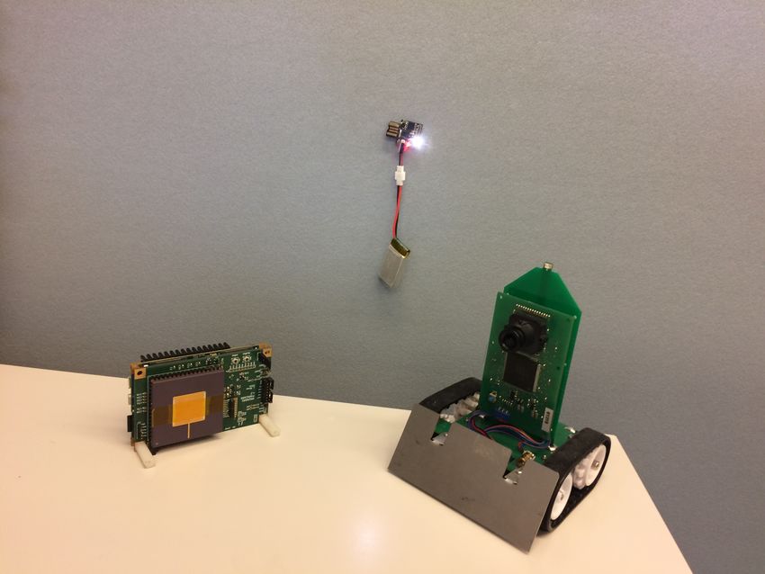
Authorized licensed use limited to: Stanford University. Downloaded on March 27,2021 at 00:32:30 UTC from IEEE Xplore. Restrictions apply.head direction neurons (IHD), and two populations that shift
the activity to the right (SR) or to the left (SL), respectively.
A schematic representation of the networks is shown in Fig. 3.
HD All populations are connected as ring networks (the figure does
not depict the closure of the ring in order to obtain a better
illustration of the synaptic connectivity).
SR
HD neurons are connected in a WTA network, in which
neurons amplify their local activity by being excitatorily con-
nected to their nearest neighbors and globally inhibit each
IHD other. As a consequence, the network “selects” the local
group that receives the strongest excitation and at the same
time suppresses the activity of all other neurons via global
inhibition, thus creating a bump of activity on the ring attractor
network.
Each active HD neuron inhibits every shift neuron except
Fig. 3: The neural network architecture with the connections for the ones with the same index and the ones to the immediate
between five neural populations: head direction (HD), shift right and left, allowing for local activity in the shift network
right (SR), integrated head direction (IHD), and angular ve- when it is globally stimulated due to movement (by the AV
locity populations drive left (DL) and drive right (DR). The populations). This connectivity pattern is more robust than
shift left (SL) population is not shown for clarity. The IMU a connectivity pattern in which SR neurons integrate two
and DVS populations reset the activity bump in the IHD pop- excitatory inputs – from the HD and AV populations.
ulation, driven by the compass- and DVS-signal, respectively.
Arrows mark excitatory, circles inhibitory synapses (only a The two distinct shift populations (SL and SR) connect
subset of recurrent connections is shown). to the IHD population with asymmetric network connectivity
[2], [18], [23], shifting the bump to the right (SR) and to the
left (SL), respectively. With its one-to-one mapping to the HD
neurons, the IHD population moves the HD activity bump to
250
DVS
IHD the estimated updated orientation.
Source neuron address
200
HD Thus, when the robot turns, one of the angular velocity
populations (DR or DL) excites the whole shift population,
but will only induce activity in the local region of the shift
150
SL population due to the inhibition from the HD population.
SR
Active shift neurons excite the IHD neurons to the immediate
100
right or left and induce a bump of activity in IHD population
shifted relative to the bump in the HD population. Finally, the
50
IHD neurons strongly feed into the HD population moving the
AV activity bump smoothly with integration or abruptly by external
0
0 50 100 150 200 250 reset.
Target neuron address
IMU is a neuronal population that, when activated, resets
Fig. 4: The synaptic connectivity matrix that implements the bump in the IHD population to the true orientation esti-
the architecture on the ROLLS chip. Colors encode synaptic mated with the IMU compass on the Pushbot. Moreover, when
weights of the recurrent connections on the chip (red for a visual landmark is detected, the DVS population is stimulated
positive and blue for negative weights). Labels indicate the by the DVS events and moves the IHD activity bump to
neural populations (as in Fig. 3) the correct position. The visual landmark corresponds to a
blinking beacon and is seen once in every full rotation. Cross-
inhibition between DL-SR and DR-SL populations reduces the
on soft winner take all (WTA) recurrent interactions, which
chance of stochastic spiking. The excitatory WTA kernel of
have later been linked to representations in the HD system of
width two was chosen to make the localized activity more
rats [18]. Attractor models based on DNFs can account for
robust and stable. The synaptic connectivity matrix set on the
various attributes of HD cells, e.g. neurons firing at a steady
neuromorphic chip is shown in Fig. 4.
rate when facing the preferred direction even in darkness and
shifting their activity according to self-motion.
IV. R ESULTS
A. Spiking Neural Network Architecture In our robotic experiments, we put the robot in an arena
The core of the presented system is a neuromorphic neural with a blinking LED fixed on one of the walls (Fig. 2). In the
network architecture that integrates the robot’s angular velocity beginning of each trial, the IMU state is read to obtain the true
to compute its orientation. The architecture consists of six heading orientation. The robot turns around its axis and at the
neuronal populations: An angular velocity population (AV) that end of the rotation the IMU state is read again. The difference
is composed of a drive right (DR) and a drive left (DL) sub- between the orientation represented by the activity of the HD
populations, the head-direction neurons (HD), the integrated neurons and the true orientation, given by the IMU data, is
978-1-5386-4881-0/18/$31.00 ©2018 IEEE
Authorized licensed use limited to: Stanford University. Downloaded on March 27,2021 at 00:32:30 UTC from IEEE Xplore. Restrictions apply.(a) Without visual reset. (b) With visual reset.
Fig. 5: Spiking activity of neurons on chip using the DVS-based reset (right) and without visual information (left). The figure
shows how the visual correction aids the head direction network to have a more precise orientation estimation, limiting error
accumulation (see “Accumulated error” in the left plot). IMU checks in the beginning and end of the trial are marked by red
spikes of the IMU population. DVS population is activated when the visual landmark is detected (≈ 13s and 26s).
Fig. 6 shows that the mean deviation of the neurally
estimated orientation does not diverge both with and without
visual reset, but fluctuates around zero. This means that the
neuronally estimated shift corresponded to the angular velocity
of the robot and there was no constantly accumulating error
due to bad calibration. However, using visual reset makes the
system more reliable and less prone to neuronal or missmatch
induced drift. This leads to a smaller mean error and a narrower
standard deviation. By performing a χ2 test, we assessed that
the system with visual reset is compatible with having an offset
of zero as time progresses.
V. C ONCLUSION
In this work, we realized a neural head direction architec-
Fig. 6: The mean of the accumulated error over time with ture on a neuromorphic device with spiking silicon neurons
and without visual reset. Error bars represent the one sigma that can integrate angular velocity information in order to
spread of error measurements over dozens of trials. Data-points maintain an internal representation of orientation. The activity
without visual feedback were shifted by one (to the right) to of the silicon exponential I&F neurons is driven in a closed
avoid graphic overlaps. sensory-motor loop. By detecting a visual landmark, the accu-
mulated error can be corrected, as demonstrated in Figs. 5,6.
calculated. This difference represents the error of the system In future work, we plan to use multiple AV (drive) pop-
and is referred to as ∆, measured in number of neurons. ulations for different angular velocities, leading to a number
of shift populations that produce shifts of different amplitude.
The spiking activity during two example trials can be seen Moreover, the weights between AV and shift populations can
in Fig. 5. It can be observed that the path integration with be made plastic to adjust the activity shift to better correspond
visual reset (right plot) is more precise due to the correction to the actual angular velocity. Finally, blinking LEDs with
of the accumulated error. different frequencies can be placed at various orientations
and on-chip plastic synapses of the silicon neurons can learn
The reliability of the system was tested by analyzing the position of each LED, effectively forming a map of the
the difference between the HD neurons activated through robot’s surroundings. The LEDs can be replaced by an object-
integration and the neurons that were activated by the IMU recognition system.
reset. Fig. 6 shows the mean error for the system with and
without visual correction, measured as the robot turns for up Combining path integration with the visual correction is the
to 45 seconds. We have conducted many runs of the system first step towards robotic localization implemented in neuro-
(between 16 and 52 per data point in the plot) with rotations morphic hardware. Future work will use a larger neuromorphic
both to the right (e.g., Fig. 5b) and to the left (e.g., Fig. 5a). device to add path integration for translation and to establish
This also allowed us to estimate the standard deviation of the a map of the environment using plastic on-chip connections,
error over time and revealed that it grows for trials without leading towards a complete neuromorphic simultaneous local-
visual reset. ization and mapping (SLAM) system.
978-1-5386-4881-0/18/$31.00 ©2018 IEEE
Authorized licensed use limited to: Stanford University. Downloaded on March 27,2021 at 00:32:30 UTC from IEEE Xplore. Restrictions apply.ACKNOWLEDGMENT [16] P. Lichtsteiner, C. Posch, and T. Delbruck, “A 128 X 128 120db 30mw
asynchronous vision sensor that responds to relative intensity change,”
The authors would like to thank Giacomo Indiveri and Ning 2006 IEEE Int. Solid State Circuits Conf. - Dig. Tech. Pap., pp. 2004–
Qiao for their support throughout the project. This project was 2006, 2006.
funded by the UZH grant FK-16-106, ZNZ fellowship, and the [17] S. C. Liu and T. Delbruck, “Neuromorphic sensory systems,” pp. 288–
SNF grant “Ambizione” PZOOP2 168183. 295, 2010.
[18] K. Zhang, “Representation of Spatial Orientation by the Intrinsic Dy-
namics of the Head-Direction Cell Ensemble: A Theory,” J. Neurosci.,
vol. 16, no. 6, pp. 2112–2126, 1996.
R EFERENCES [19] J. D. Seelig and V. Jayaraman, “Neural dynamics for landmark
orientation and angular path integration,” Nature, vol. 521, no.
[1] J. S. Taube, R. U. Muller, and J. B. Ranck, “Head-direction cells 7551, pp. 186–191, 2015. [Online]. Available: http://www.nature.com/
recorded from the postsubiculum in freely moving rats. I. Description doifinder/10.1038/nature14446
and quantitative analysis.” J. Neurosci., vol. 10, no. 2, pp. 420–35, 1990.
[20] X. J. Wang, “Synaptic basis of cortical persistent activity: the impor-
[Online]. Available: http://www.ncbi.nlm.nih.gov/pubmed/2303851
tance of NMDA receptors to working memory.” J. Neurosci., vol. 19,
[2] X. Xie, R. H. R. Hahnloser, and H. S. Seung, “Double-ring network no. 21, pp. 9587–9603, 1999.
model of the head-direction system,” Phys. Rev. E - Stat. Nonlinear,
[21] H. R. Wilson and J. D. Cowan, “A mathematical theory of the functional
Soft Matter Phys., vol. 66, no. 4, 2002.
dynamics of cortical and thalamic nervous tissue.” Kybernetik, vol. 13,
[3] P. Song, “Angular Path Integration by Moving ”Hill of Activity”: no. 2, pp. 55–80, 1973.
A Spiking Neuron Model without Recurrent Excitation of the [22] S. ichi Amari, “Dynamics of pattern formation in lateral-inhibition type
Head-Direction System,” J. Neurosci., vol. 25, no. 4, pp. 1002–1014, neural fields,” Biol. Cybern., vol. 27, no. 2, pp. 77–87, 1977.
2005. [Online]. Available: http://www.jneurosci.org/cgi/doi/10.1523/
JNEUROSCI.4172-04.2005 [23] A. Redish, A. Elga, and D. Touretzky, “A coupled attractor model of
the rodent head direction system,” Netw. Comput. Neural Syst., vol. 7,
[4] G. Indiveri, E. Chicca, and R. J. Douglas, “Artificial cognitive systems: no. 4, pp. 671–685, 1996.
From VLSI networks of spiking neurons to neuromorphic cognition,”
Cognit. Comput., vol. 1, no. 2, pp. 119–127, 2009.
[5] S. B. Furber, D. R. Lester, L. A. Plana, J. D. Garside, E. Painkras,
S. Temple, and A. D. Brown, “Overview of the SpiNNaker system
architecture,” pp. 2454–2467, 2013.
[6] B. V. Benjamin, P. Gao, E. McQuinn, S. Choudhary, A. R. Chan-
drasekaran, J. M. Bussat, R. Alvarez-Icaza, J. V. Arthur, P. A. Merolla,
and K. Boahen, “Neurogrid: A mixed-analog-digital multichip system
for large-scale neural simulations,” Proc. IEEE, vol. 102, no. 5, pp.
699–716, 2014.
[7] E. Chicca, F. Stefanini, C. Bartolozzi, and G. Indiveri, “Neuromorphic
electronic circuits for building autonomous cognitive systems,” Proc.
IEEE, vol. 102, no. 9, pp. 1367–1388, 2014.
[8] S. Koziol, S. Brink, and J. Hasler, “A neuromorphic approach to path
planning using a reconfigurable neuron array IC,” IEEE Trans. Very
Large Scale Integr. Syst., vol. 22, no. 12, pp. 2724–2737, 2014.
[9] N. Qiao, H. Mostafa, F. Corradi, M. Osswald, D. Sumislawska, G. In-
diveri, and G. Indiveri, “A Re-configurable On-line Learning Spiking
Neuromorphic Processor comprising 256 neurons and 128K synapses,”
Frontiers in neuroscience, vol. 9, no. February, 2015.
[10] J. Conradt, R. Berner, M. Cook, and T. Delbruck, “An
embedded AER dynamic vision sensor for low-latency pole
balancing,” 2009 IEEE 12th International Conference on
Computer Vision Workshops, ICCV Workshops, pp. 780–785, 2009.
[Online]. Available: http://citeseerx.ist.psu.edu/viewdoc/download?doi=
10.1.1.192.1328{\&}rep=rep1{\&}type=pdf
[11] A. Olofsson, T. Nordström, and Z. Ul-Abdin, “Kickstarting high-
performance energy-efficient manycore architectures with Epiphany,”
Conference Record - Asilomar Conference on Signals, Systems and
Computers, vol. 2015-April, no. May, pp. 1719–1726, 2015.
[12] K. A. Boahen, “Point-to-Point Connectivity Between Neuromorphic
Chips using Address-Events,” Ieee Transactions on Circuits
& Systems, vol. 47, no. 5, pp. 416–434, 1999. [Online].
Available: https://web.stanford.edu/group/brainsinsilicon/pdf/00{\ }
journ{\ }IEEEtsc{\ }Point.pdf
[13] T. Delbruck, R. Berner, P. Lichtsteiner, and C. Dualibe, “32-bit config-
urable bias current generator with sub-off-current capability,” in ISCAS
2010 - 2010 IEEE Int. Symp. Circuits Syst. Nano-Bio Circuit Fabr. Syst.,
2010, pp. 1647–1650.
[14] G. Indiveri, E. Chicca, and R. Douglas, “A VLSI Array of Low-Power
Spiking Neurons and Bistable Synapses With Spike-Timing Dependent
Plasticity,” vol. 17, no. 1, pp. 211–221, 2006.
[15] R. Brette and W. Gerstner, “Adaptive exponential integrate-and-
fire model as an effective description of neuronal activity,” J.
Neurophysiol., vol. 94, no. 5, pp. 3637–3642, 2005. [Online].
Available: http://www.ncbi.nlm.nih.gov/pubmed/16014787
978-1-5386-4881-0/18/$31.00 ©2018 IEEE
Authorized licensed use limited to: Stanford University. Downloaded on March 27,2021 at 00:32:30 UTC from IEEE Xplore. Restrictions apply.You can also read