A NOVEL COMPACT BROADBAND AND RADIATION EFFICIENT ANTENNA DESIGN FOR MEDICAL IOT HEALTHCARE SYSTEM
←
→
Page content transcription
If your browser does not render page correctly, please read the page content below
MBE, 19(4): 3909–3927.
                                                                           DOI: 10.3934/mbe.2022180
                                                                           Received: 28 December 2021
                                                                           Revised: 25 January 2022
                                                                           Accepted: 07 February 2022
                                                                           Published: 11 February 2022
http://www.aimspress.com/journal/MBE

Research article

A novel compact broadband and radiation efficient antenna design for
medical IoT healthcare system

Zaheer Ahmed Dayo1,*, Muhammad Aamir1,*, Shoaib Ahmed Dayo2, Imran A. Khoso3,
Permanand Soothar4, Fahad Sahito5, Tao Zheng6, Zhihua Hu1,* and Yurong Guan1

1
    College of Computer Science, Huanggang Normal University, Huangzhou 438000, China
2
    Department of Industrial Engineering, Universita Degli Studi Di Salerno (University of Salerno)-Via
    Giovanni Paolo II, Fisciano (SA) 132-84084, Italy
3
    College of Electronic and Information Engineering, Nanjing University of Aeronautics and Astronautics,
    China
4
    School of Electronic and Optical Engineering, Nanjing University of Science and Technology, Nanjing
    210094, China
5
    College of Electronic and Communication Engineering, Beijing University of Posts and Telecommunication,
    Beijing 100879, China
6
    Deputy General Manager, Nanjing Hurys Intelligent Technology Company Limited, Nanjing, China

* Correspondence: Email: zaheerdayo@hgnu.edu.cn, dayo.zaheer@hotmail.com,
  aamirshaikh86@hotmail.com, huzhihua@hgnu.edu.cn.

Abstract: This paper investigates and develops a novel compact broadband and radiation efficient
antenna design for the medical internet of things (M-IoT) healthcare system. The proposed antenna
comprises of an umbrella-shaped metallic ground plane (UsMGP) and an improved radiator. A
hybrid approach is employed to obtain the optimal results of antenna. The proposed solution is
primarily based on the utilization of etching slots and a loaded stub on the ground plane and
rectangular patch. The antenna consists of a simple rectangular patch, a 50 Ω microstrip feed line,
and a portion of the ground plane printed on a relatively inexpensive flame retardant material (FR4)
thick substrate with an overall compact dimension of 22 × 28 × 1.5 mm3. The proposed antenna
offers compact, broadband and radiation efficient features. The antenna is carefully designed by
employing the approximate calculation formulae extracted from the transmission line model. Besides,
the parameters study of important variables involved in the antenna design and its influence on
impedance matching performance are analyzed. The antenna shows high performance, including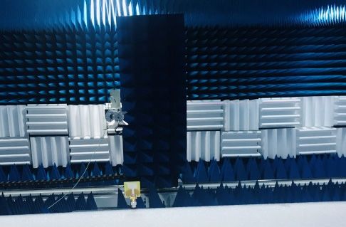
3910

impedance bandwidth of 7.76 GHz with a range of 3.65–11.41 GHz results in 103% wider relative
bandwidth at 10 dB return loss, 82% optimal radiation efficiency in the operating band, reasonable
gain performance, stable monopole-shaped radiation patterns and strong current distribution across
the antenna lattice. The suggested antenna is manufactured, and simulation experiments evaluate its
performance. The findings indicate that the antenna is well suited for medical IoT healthcare systems
applications.

Keywords: compact; broadband; radiation efficiency; umbrella-shaped metallic ground plane
(UsMGP); modified radiator and medical internet of things (M-IoT) healthcare systems

1.   Introduction

      The great progress of wireless medical healthcare systems needs compact broadband and
efficient antennas. The optimal performance of these systems is achieved with the robust antenna
designs. Recently, compact antenna devices have been playing an important role. These devices are
part of the modern healthcare wireless communication system. Therefore, designing a compact
antenna with the best performance is still a challenging task for active antenna designers. In
addition, different types of antennas with different specifications covers modern heterogeneous
wireless applications have been reported in the literature [1–4]. The existing antenna designs still
faces many challenges, such as reasonable antenna behaviour, narrow bandwidth (BW), moderate
radiation efficiency and acceptable gain with the comparatively larger size.
      In recent years, there has been remarkable research and advancement in the medical internet
of things (M-IoT) and healthcare systems and services [5,6]. The M-IoT has proved its ability to
connect disparate pieces of medical equipment, sensors, actuators, and healthcare professionals to
provide superior medical services at a remote location [7–10]. As a result, many benefits have been
achieved, including optimized patient safety, lower healthcare costs, increased healthcare service
accessibility and increased operational efficiency in M-IoT field [11,12]. The M-IoT technology
encompasses heterogeneous wireless communication applications (HWCA) used in smart gadgets,
control and automation systems, wireless sensor networks and smart grids [13,14]. A significant
role is played by the efficient antenna system utilized in M-IoT end devices. An M-IoT system uses
an efficient antenna design with features including compact, low-cost, broadband, low power
consumption, radiation efficiency, simple configuration, and monopole-like radiation patterns.
      Moreover, researchers are drawn to a high-performance broadband system due to its fast data
rate, high capacity, simplicity, and low operational power. Nowadays, scholars concentrate their
efforts on developing antennas with novel structures and increased compact properties. The antennas
may utilize the entire spectrum without causing interference in a confined space. These antennas are
distinguished by their broad bandwidth, high gain, small size, and great radiation efficiency. The
antennas can be used to cover M-IoT, modern heterogeneous wireless communication applications
(HWCA), including civil and military wireless access services, personal communication system,
airborne, naval, terrestrial radio detection and ranging (RADAR) [15], high-speed modern M-IoT
[16], high-precision positioning satellite and navigational systems and so on. The telecommunication
regulatory authority radio frequency allocation board of the Federal Communication Commission
(FCC) has apportioned spectrum for multiple HWCA, such as C-band from 4 to 8 GHz, X-band from

Mathematical Biosciences and Engineering                                  Volume 19, Issue 4, 3909–3927.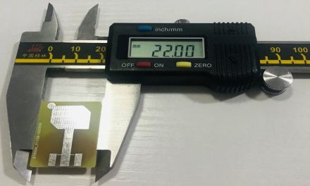
3911

8 to 12 GHz, H-band from 6 to 8 GHz [17], and airborne, terrestrial and naval radars from 8.5 to 10.5
GHz, respectively.
      References [18–21] have been made to current research on miniature high-performance planar
antennas for modern wireless communication applications. Diverse radiator shapes and modern
antenna topologies, including folded C-shaped radiator and disc-shaped antenna for radio
frequency identification and broadband applications reported in [22,23]. In references [24–26], an
elliptical wide-slot antenna with a cross-shaped parasitic component, redesigned antenna lattices
utilizing defected ground structures (DGS), and meta-material resonator inspired antennas for
ultra-wideband (UWB) applications were presented. A compact circular staked patch antenna
achieved a wide BW of 5.02 GHz [27]. Another hexagonal probe-fed antenna using a flangeless
connector exhibited 8.3 GHz BW with a reasonable gain performance developed in [28]. The authors
used various antenna shapes to achieve a broad impedance BW and did not emphasize the radiation
efficiency. A miniature trident antenna by engraving multi-resonant slots and annular sector for
UWB applications were presented in [29]. The broadband antenna with loading u-shaped patch
engraved on the compact substrate 40 × 50 × 1.575 mm3; achieved around 40% fractional BW have
been designed in [30]. Another work presented the high-performance Fabry-Perot cavity antenna using
a beam switched approach. The designed antenna attained the 24% relative BW and 17.6 dBi peak
realized gain at a given frequency range [31]. However, the developed antennas include intricate
topologies and higher antenna diameters. Roberto Vincenti Gatti et al. designed the single layer
wideband antenna using a microstrip feeding line. The authors utilized the square and rectangular
patches with compact sizes of 9.85 × 9.85 mm2 and 9.403 × 11.593 mm2. The presented work
achieved a reasonable BW of 6.12% and 3.17% in the operating band [32]. The stubs loaded patch
DGS, and numerous designing concepts of broadband antennas were utilized in [33,34]. A dual
wideband antenna with parasitic slot and radiator was reported in [35]. The proposed antenna
achieved 2.4 to 6.1 GHz and 9.4 to 13.8 GHz impedance BW. The method for BW enhancement
has been suggested in [36]. The authors achieved the broad BW with compact fractal metal
structures. A wideband antenna with notch band features and improved patch antenna design were
suggested in [37,38]. However, the employed approaches were complex, resulting in computational
complexity. A miniaturized broadband patch and slot antennas for ground penetrating radar (GPR)
and multiple-input multiple-output (MIMO) wireless terminal applications were reported in [39,40].
The antennas enhanced results were achieved with larger substrate dimensions.
      Further, a new palm tree structure antenna with wideband features proposed in [41]. The antenna
achieved the broadband BW ranging from 4.0–10.4 GHz. The triple band notch wideband
panda-shaped antenna exhibited reasonable results across the frequency span was demonstrated in [42].
Recently, UWB, single and dual resonant antennas for spectrum sensing and moisture content
measurement applications reported in [16,43]. The compact antennas with asymmetric coplanar strip
(ACS) feeding and coplanar waveguide (CPW) feeding approaches were reported in [44–46]. The
designed antennas achieved the triple and pentaband features by using the material selection and
different shaped slots. The authors have used different laminates to achieve good performance of the
antennas. Another new design of antenna fed with CPW feed line achieved reasonable gain
performance and 67% efficiency for satellite forward mission features proposed in [47]. The
designed antenna has the overall size of 40 × 40 mm2 imprinted on Roggers 5880 laminate. Further,
the reconfigurable and versatile designing methods for single and multiple elements were analyzed
in [48–50]. An ultra-compact triangular-shaped ground plane antenna have been proposed for

Mathematical Biosciences and Engineering                                  Volume 19, Issue 4, 3909–3927.
3912

multiband features [51]. Besides, a broadband antenna for modern communication application
reported in [52]. The antenna with an inverted omega-shaped ground plane achieved wideband and
high gain features reported in [53]. A miniaturized crossed dipole antenna with a size of 30.3 × 51.4
× 0.508 mm3 achieved the 28% fractional BW, and 1 × 8 dielectric resonator antenna (DRA) array
exhibited an optimal gain of 12 dBi and BW of 6 GHz were reported in [54,55]. The employed
antenna designing methods were complex and time-consuming. The antenna’s high-performance
results including good impedance BW and high gain demonstrated in [15,56]. The results were
accomplished using an array and a single layer stub loaded approaches. The slotted bowtie elements
transmit array for UWB applications was proposed in [57]. The authors designed different antenna
geometries with multiple functionalities for different modern communication applications reported
in [58,59]. The other studies about the high-performance dipole antennas using cavity backed
approach and modified taegeuk structure were reported in [60–62].
     This article proposes a revolutionary compact broadband and radiation efficient antenna with an
umbrella-shaped metallic ground plane (UsMGP). A new hybrid approach is employed to obtain the
optimal antenna results. The primary reason for this compact antenna design is to introduce a novel
structure that may achieve wide impedance bandwidth (BW), optimal radiation efficiency and stable
omni-directional radiation patterns. The proposed method mainly relies on etching slots and loaded
stub used on the ground plane and rectangular patch. The proposed antenna includes a simple
rectangular patch, 50 Ω microstrip feed line, and ground plane. The antenna design is printed on a
thick layer of low-cost flame retardant (FR4) substrate material. The antenna is designed to be
compact with an overall size of 22 × 28 × 1.5 mm3. The parameters study of important variables
involved in the antenna design and its influence on impedance matching performance are analyzed.
The proposed antenna model obtains an impedance bandwidth of 7.76 GHz with a range of 3.65–11.41
GHz results in a wider fractional BW of 103%, a reasonable gain of 4.58 dBi, stable monopole like
radiation pattern and good 82% radiation efficiency features. The suggested antenna design has been
simulated, constructed, and verified experimentally. As demonstrated by simulation and experimental
findings, the suggested compact broadband and radiation efficient antenna is a superior solution for
M-IoT healthcare systems.
     The remainder of the manuscript is organized as follows. Sections 2 and 3 describe the proposed
antenna’s technological plan and evolution stages. Section 4 comprises the simulation results and
discussion; Section 5 includes experimentally validated results; Section 6 contains a comparison to
recently published state-of-the-artwork. Finally, Section 7 summarizes the concluding observations.

2.   Antenna technical design strategy

      In this section, the proposed antenna technical design strategy is briefly described. Before start
designing the antenna lattice, the type of antenna, selection of the material and its thickness is very
important. Based on the requirement, the planar monopole antenna (PMA) has been focused due to
its good performance and low-cost FR4 epoxy substrate material is used to curb the fabrication cost
of the antenna. Afterwards, selection of suitable electromagnetic (EM) software has been decided.
The antenna is designed and simulated by using the high frequency structure simulator (HFSS)
version 13.0. The step by step flow of technical strategical plan of the proposed antenna is briefly
explained. The proposed antenna is designed by employing the transmission line model equations.
The antenna is designed using the following technical approach illustrated in Figure 1.

Mathematical Biosciences and Engineering                                    Volume 19, Issue 4, 3909–3927.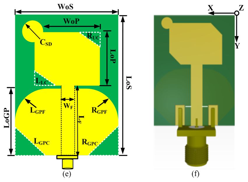
3913
Figure 1. Flow chart of designed technical strategy.
Besides, the approximated mathematical formulation based on the transmission line model is
also expressed here. The size of the radiating patch, dielectric substrate, feed line and partial ground
plane of the proposed antenna can be obtained by the following approximated Eqs (1) to (9). The
value of patch length can be obtained by using the formula [52]:
LoP Leff 2 L (1)
where, LoP represents the patch length, Leff is the effective length, and ΔL is the normalized
extension in length. Moreover, Leff can be calculated as follow:
V0
Leff (2)
2 f reff
where, V0 denotes the speed of light in a vacuum, f represents the resonance frequency, and εreff
indicates the effective dielectric constant. Furthermore, εreff can be calculated as follow:
reff 1 r 1
reff (3)
2 HoS
2 1 12
WoS
where, εr is the dielectric constant of the substrate, HoS and WoS, represents the dielectric substrate's
height and width, respectively. Moreover, normalized extension in length due to the fringing effect
can be calculated as follows:
Mathematical Biosciences and Engineering Volume 19, Issue 4, 3909–3927.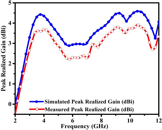
3914
WoP
reff 1 HoS 0.264
L 0.412 HoS (4)
0.258 WoP 0.8
reff
HoS
where, WoP represents the width of the patch. Moreover, the width of the patch (WoP) and length of
the partial ground plane (LoGP) can be calculated as follow:
V0 2
WoP (5)
2f reff 1
LoGP LoP 6 HoS (6)
where, LoP is the length of the patch. However, substrate thickness (HoS), width of the ground plane
(WoGP), feed line length (LoF) and guided wavelength (λg) can be calculated as follow:
0.606
HoS (7)
r
WoGP WoP 6 HoS (8)
g
LoF ; g (9)
4 reff
3. Antenna evolution stages and designed layout
The suggested antenna model’s development and architecture are depicted in Figure 2(e)–(f). The
designed antenna is etched on a low-cost FR4 epoxy thick substrate material with a relative dielectric
permittivity of εr = 4.4, a loss tangent value of δ = 0.02, and a copper thickness of 0.035 mm. The
suggested antenna is 28 mm long, 22 mm wide, and 1.5 mm thick. The intended antenna was created
by modifying the metallic ground plane (MGP) and creating a small rectangular patch. On the top side
of the laminate, a basic rectangular patch with compact dimensions of (10.5 × 14.0 mm2) and a 50 Ω
microstrip feed structure are etched, and a small miniature partial ground plane (PGP) is etched on the
flip side of the substrate, as shown in Figure 2(a).
The chamfered operation of 5.0 mm is performed on the upper left and right edges of the PGP and
constructs the antenna model-2 as shown in Figure 2(b). Further, an 8.0 mm fillet operation is
performed on lower left and right edge of chamfered PGP to form an umbrella-shaped metallic ground
plane (UsMGP), as depicted in Figure 2(c). The purpose of making this change on the PGP is to realize
the high-performance features of the antenna. Then, as illustrated in Figure 2(d), trim the upper-right
edge of the compact rectangular patch using a 3.0 mm fillet operation to create the antenna model-4.
Finally, the proposed antenna model is constructed by again applying fillet operation of 3.0 mm
on the lower-left edge of rectangular patch and the loaded circular disc stub with the minimum size of
1.5 mm on the upper-right edge of the compact improved rectangular patch as elucidated in Figure 2(e).
The variables and their optimal values of the proposed antenna design are listed in Table 1. The
electromagnetic high frequency structure simulator (HFSS) software program develops and simulates
the proposed antenna. Moreover, the proposed antenna model is also designed on the three
dimensional (3D) altium designer (AD) tool widely used in the industry, as shown in Figure 2(f).
Mathematical Biosciences and Engineering Volume 19, Issue 4, 3909–3927.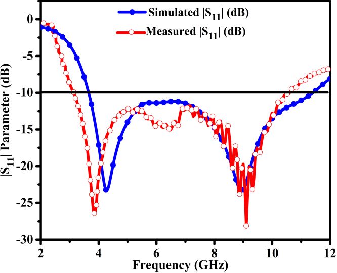
3915

      Figure 2. Proposed antenna development process, (a) simple partial ground plane (PGP),
      (b) chamfered PGP, (c) umbrella-shaped metallic ground plane (UsMGP), (d) fillet
      radiator and UsMGP, (e) proposed antenna prototype, (f) 3D designed antenna model with
      SMA connector.

           Table 1. Proposed antenna designed variables and optimized values (unit: mm).

Defined variables       Optimized value           Defined Variables      Optimized value
WoS = WoGP              22.0                      LoS                    28.0
HoS                     1.5                       LoGP                   14.5
LGPC = RGPC             8.0                       LGPF = RGPF            5.0
WF                      3.1                       LF                     17.0
LoP                     14.0                      WoP                    10.5
RUC = LLC               3.0                                           CSD1.5

    The performance of the evolved antenna models in terms of return loss (|S11|) is depicted in
Figure 3; it is discovered that the initially designed antenna model obtained a wide impedance
bandwidth (BW) of 4.9 GHz with a range of 3.9–8.8 GHz at a return loss of 10 dB. Additionally, the
antenna model-2 has an impedance BW of 5.98 GHz and a frequency range of 3.78–9.76 GHz. The
impedance BW is improved by 22% compared to the proposed antenna model-1. The partial ground

Mathematical Biosciences and Engineering                                Volume 19, Issue 4, 3909–3927.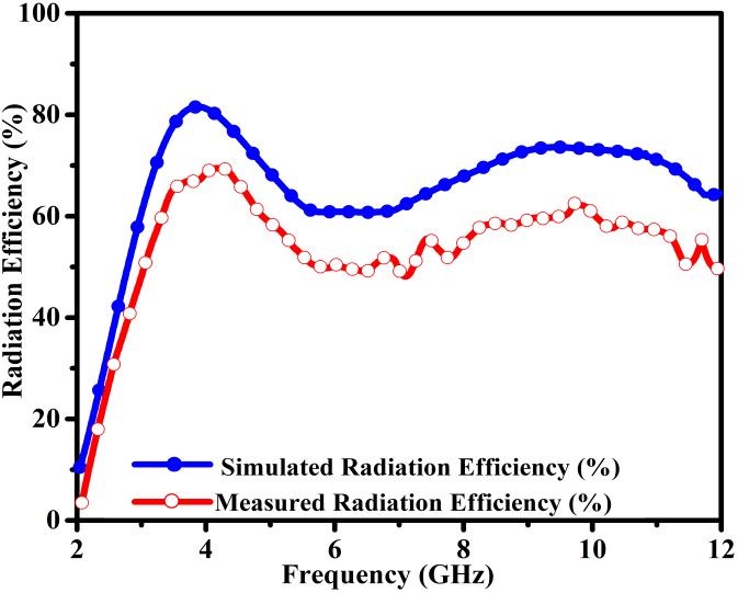
3916

plane (PGP) is used to achieve this increase in impedance BW. Likewise, the antenna model-3 is
designed to have an impedance BW of 6.08 GHz and a frequency range of 3.72–9.8 GHz. Moreover,
the suggested antenna type achieves a greater impedance BW of 6.19 GHz over the 3.76–9.95 GHz
frequency range. Finally, the proposed antenna model obtains an impedance BW of 7.76 GHz with a
3.65–11.41 GHz frequency range. Also, it can be seen that the proposed antenna model’s impedance
BW has been enhanced by 58.4% when compared to the initial antenna design model.

      Figure 3. |S11| performance of overall antenna designed prototypes across the operable
      frequency.

4.   Simulation results and discussion

     This section explains the parametric analysis of the variables used to develop the proposed
antenna design. The parameters associated with the intended variables can be examined by employing
the electromagnetic high frequency structure simulator (HFSS) software package for rigorous multiple
times simulation. The main purpose of this study is to obtain proper impedance matching, wide
impedance BW and best performance results for the proposed antenna.

4.1. Influence of LoGP and WoP

     The size of the length of the ground plane (LoGP) and width of the patch (WoP) influences the
proposed antenna impedance matching performance and resonance tuning features. As shown in
Figure 4(a), the proper impedance matching and wider BW are achieved at a maximum 14.5 mm value
of the ground plane. Likewise, the second resonance tunability has been achieved at the maximum
value of the variable. Further, the proper matching, wider impedance BW and second resonance tuning
are achieved at the value of WoP 14.0 mm, as shown in Figure 4(b).

Mathematical Biosciences and Engineering                                 Volume 19, Issue 4, 3909–3927.
3917
(a) (b)
Figure 4. Influence of variables over the entire operable frequency range, (a) length of
ground plane LoGP, (b) width of the patch (WoP).
4.2. Influence of LoP and HoS
The length of the patch (LoP) and the thickness of the substrate (HoS) strongly influence the
impedance matching, BW and frequency tuning performance of the proposed antenna. It can be
analyzed from Figure 5(a); the antenna matching performance is achieved at the patch value of 10.5
mm. Further, substrate thickness strongly affects the impedance matching performance of the
proposed antenna, as shown in Figure 5(b). It can be seen that at the lower value of the thickness of the
substrate, the antenna exhibited the dual-band frequency response. The wider impedance BW is
achieved at the optimized substrate thickness value of 1.5 mm.
(a) (b)
Figure 5. Influence of parameters, (a) length of the patch (LoP) and (b) substrate thickness
(HoS) across the operable frequency span.
Mathematical Biosciences and Engineering Volume 19, Issue 4, 3909–3927.3918
4.3. Surface current distribution (JSURF)
The recommended antenna model’s simulated result analysis of the current density at two
resonances is presented in Figure 6(a)–(b). When the proposed antenna resonates at 4.82 GHz, it
exhibits a significant distribution current across the entire patch, feeding line, and umbrella-shaped
ground plane (UsMGP). Additionally, at 8.96 GHz, a slight shift in current is evaluated at the patch's
upper edge and the UsMGP’s lower left and right edges. As a result of the data stated previously, it can
be inferred that the suggested antenna maneuvers admirably throughout the operable frequency range.
(a) (b)
Figure 6. Surface current distribution of the proposed antenna at different frequencies, (a)
4.28 GHz, (b) 8.96 GHz.
5. Experimental verified results
This section discusses the proposed antenna model’s experimentally validated outcomes. The
measured and simulated values for critical antenna characteristics such as |S11| (dB), peak realized gain
(dBi), radiation efficiency (%), and radiation patterns throughout the standard plane are compared,
investigated, and analyzed.
5.1. Return loss |S11| parameter
The manufactured antenna prototype is depicted in Figure 7(a)–(b). Before evaluating the return
loss of the manufactured antenna sample, the vector network analyzer (VNA) is calibrated properly.
The antenna model is linked to the VNA’s single port. Figure 8 illustrates the simulation and
measurement results for the proposed and manufactured antenna. The manufactured antenna sample's
return loss (|S11|) parameter performance is determined using the Agilent PNA 5230C VNA. As
illustrated in Figure 8, the antenna’s simulation model has a broader impedance bandwidth (BW) of
7.76 GHz, with a lower frequency of 3.65 GHz and a higher frequency of 11.41 GHz. Similarly, at 4.28
GHz and 8.96 GHz, two resonances are recorded. Additionally, the antenna's constructed model
exhibits two resonances identical to the simulation model. As can be seen, the lower resonance has
Mathematical Biosciences and Engineering Volume 19, Issue 4, 3909–3927.3919
been somewhat pushed away from 3.9 GHz compared to the simulation results. Due to the SMA
connector’s faulty welding and the lossy substrate material, discrepancies in the results have been
noted.
(a) (b)
Figure 7. Fabricated antenna model, (a) front view, (b) back view.
Figure 8. Simulation and measured results of |S11| entire operable frequency span.
5.2. Peak realized gain and Radiation efficiency
Figure 9(a) illustrates the simulation and measurement findings for the proposed antenna’s peak
realized gain. At 10.5 GHz, the planned antenna model's simulation result (streaked blue line)
demonstrates a maximum gain of 4.58 dBi. Similarly, a respectable gain is noticed, for example, 4.13
dBi at 4.28 GHz and 4.42 dBi at 8.96 GHz resonances.
Mathematical Biosciences and Engineering Volume 19, Issue 4, 3909–3927.3920
(a) (b)
Figure 9: Simulation and measurement results in the entire operating frequency range, (a)
peak realized gain, (b) radiation efficiency.
Additionally, the Friis transmission equation is used to determine the measurement gain of the
fabricated antenna. As illustrated in Figure 9(a), the manufactured sample of the antenna reaches a
peak realized gain of 4.0 dBi at 10.5 GHz. Similarly, gain values of 3.7 dBi and 3.9 dBi are
achievable at 4.28 GHz and 8.96 GHz resonances. Due to the loss of samples of the indoor antenna
in the anechoic chamber during the measurement process, a difference of 0.58 dBi in the peak
realized gain between the simulation and measurement data is seen.
Figure 9(b) depicts the proposed antenna’s simulated and measured radiation efficiency. As can
be seen, the antenna's maximum efficiency at 3.9 GHz is 82%. Similarly, the proposed antenna
achieved a 78% and 70% radiation efficiency for 4.28 GHz and 8.96 GHz resonances. As can be seen,
the suggested antenna radiates efficiently within the specified frequency range. Moreover, an
efficient gain/directivity approach extracted the proposed fabricated antenna radiation efficiency. As
illustrated in Figure 9(b) (streaked red line), the suggested antenna’s fabricated sample reached a
maximum efficiency of 72% at 4.5 GHz. Similarly, for resonant frequencies of 4.28 GHz and 8.96
GHz, the manufactured antenna sample approaches 70% and 60% radiation efficiency, respectively.
Further, the difference observed in the simulation and measurement result of radiation efficiency is
less than 20%, which validates the effectiveness of the applied gain directivity approach.
5.3. Radiation pattern performance
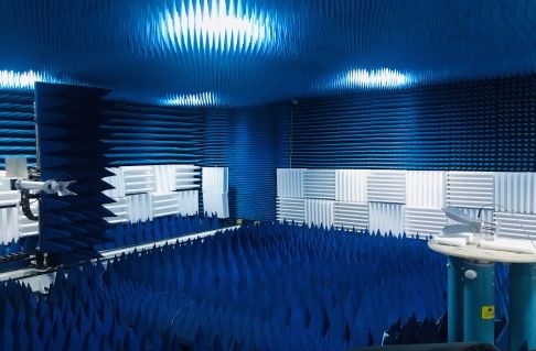
The manufactured antenna sample is put in an anechoic chamber to evaluate and validate the
suggested antenna model’s radiation pattern performance. The produced sample and ridge gap horn
antenna are positioned in the line of sight (LoS), as seen in Figure 10(a)–(b). The fabricated antenna
sample (the antenna under test) is mounted on the turntable and spun 360º.
Mathematical Biosciences and Engineering Volume 19, Issue 4, 3909–3927.3921
(a) (b)
Figure 10. Test environment of anechoic chamber room, (a) placement of ridge horn
antennas, (b) placement of antenna under test (AUT).
The radiation pattern performance of the designed and fabricated model of an antenna on the
standard planes (E-plane at Φ = 0º) and (H-plane at Φ = 90º) is shown in Figure 11(a)–(b). The
proposed antenna model has excellent performance and presents the monopole-like radiation
pattern on standard planes at the resonant frequency of 4.28 GHz, as elucidated in Figure 11(a).
The simulation and measurement results are found to be consistent. Similarly, in the H-plane, nulls
near 90º are formed.
Additionally, Figure 11(b) illustrates the suggested antenna’s radiation pattern performance across
standard planes at the resonant frequency of 8.96 GHz. The suggested antenna produces monopole-like
radiation patterns along standard planes. Further, a zero point is established about 300º in the proposed
antenna’s H-plane. As a result of the preceding discussion, it can be concluded that the simulation
results agree well with the measurement data. Similarly, for the resonant frequencies of 4.28 GHz
and 8.96 GHz, the suggested antenna exhibits stable monopole-like radiation patterns along the
standard planes.
(a) (b)
Figure 11. The proposed antenna’s simulation and measurement radiation patterns
performance, (a) @4.28 GHz, (b) @8.96 GHz, on standard planes.
Mathematical Biosciences and Engineering Volume 19, Issue 4, 3909–3927.3922
6. Performance comparison analysis
This section summarizes the suggested antenna’s performance study regarding total occupied
space, impedance bandwidth (BW), peak realized gain and radiation efficiency compared to
previously published literature. As shown in Table 2, the proposed antenna achieved high gain values
of 2.08 dBi, 1.08 dBi, and 0.58 dBi in comparison to the references [10,20,32]. The proposed
antenna exhibits the higher impedance BW of 2.74 GHz, 4.54 GHz, 3.96 GHz and 4.16 GHz in
comparison to the results reported in [10,13,19,32,53].
Further, the proposed antenna size is reduced by 34.18%, 70.8%, 86.96%, 90.98%, 74.26%,
90.94%, 41.3%, 70.83%, 85.4% and 99.69% as compared to investigated antennas in [18–
21,27,28,39,40,61,62]. Furthermore, it is noted that the antenna radiation efficiency results in
[19,21,27,28,61,62] are not reported. As shown in Table 2 and the above explained analysis, the
proposed antenna is small in size and achieves a high performance compared to most recently
examined antennas described in the literature.
Table 2. Performance comparison analysis of the proposed antenna with recently reported works.
Ref. / Year Occupied space (mm2) Bandwidth (GHz) Peak gain (dBi) Efficiency (%)
This work / 2022 616 7.76 4.58 82
[27] / 2021 936 5.02 9.3 Not reported (NR)
[28] / 2020 2116 8.3 2.5 NR
[18] / 2019 4725 3.22 3.5 90
[19] / 2019 6832 8.01 6.5 NR
[20] / 2019 2393.6 8.9 7.0 90
[21] / 2018 6804 3.8 7.35 NR
[39] / 2018 1050 10 5.0 84
[40] / 2016 2112 3.6 4.0 95
[61] / 2016 4224 7.03 11.8 NR
[62] / 2015 202500 9.8 10 NR
7. Conclusions
In this article a novel compact broadband and radiation efficient antenna for medical IoT
healthcare system has been proposed. The antenna design comprises of a compact improved radiator,
umbrella-shaped metal ground plane (UsMGP) and 50 Ω microstrip feed line. In this research, a new
hybrid technique is proposed to acquire the ideal antenna findings. The proposed approach is mainly
based on etched slots and short load stubs employed on a partial ground plane (PGP) and rectangular
patch. The suggested antenna is imprinted on a thick substrate made of a low-cost flame retardant
material (FR4). The antenna has a compact dimension of 22 × 28 × 1.5 mm3. The proposed antenna
was carefully designed by using mathematical formulations extratcetd from the transmission line
model. The parameters study of important variables involved in antenna design and its influence on
impedance matching performance are analyzed. The designed antenna shows high performance,
including 103% wide relative bandwidth, 82% best radiation efficiency, reasonable peak realized
gain performance of 4.58 dBi, stable monopole-like radiation pattern and strong current distribution
across the operable frequency span. The proposed antenna has been fabricated, and the experimental
results have been validtated through simulation experiments. The designed antenna is suitable for
M-IoT healthcare systems and covers heterogeneous wireless communication applications (HWCA).
Mathematical Biosciences and Engineering Volume 19, Issue 4, 3909–3927.3923
Moreover, The presented work can be extended further to design, simulation and fabrication of the
metamaterial inspired reconfigurable notch band MIMO antenna.
Acknowledgments
This research work is supported by the university research innovation fund of science and
technology development center of the Ministry of education of China (2020ITA05022), the Natural
Science Foundation of Hubei Province (2021CFB316), the Preliminary support project of Hubei
Social Science Foundation (21ZD137), the Hundreds of Schools Unite with Hundreds of
Counties-University Serving Rural Revitalization Science and Technology Support Action Plan
(BXLBX0847). Further, the authors greatly acknowledge the technical and industrial support
provided by the Nanjing Hurys Intelligent Technology Company Limited and the experimental
facility in measuring the fabricated antenna model at the Nanjing University of Aeronautics and
Astronautics (NUAA) China.
Conflict of interest
The authors declare that there is no conflict of interest regarding the publication of this
manuscript.
References
1. M. S. Islam, M. T. Islam, M. A. Ullah, G. K. Beng, N. Amin, N. Misran, A modified meander
line microstrip patch antenna with enhanced bandwidth for 2.4 GHz ISM-band internet of things
(IoT) applications, IEEE Access, 7 (2019), 127850–127861.
https://doi.org/10.1109/ACCESS.2019.2940049
2. M. Bansal, B. Gandhi, IoT based development boards for smart healthcare applications, in 2018
4th International Conference on Computer Communication Automation (ICCCA), (2018), 1–7.
https://doi.org/10.1109/CCAA.2018.8777572
3. K. R. Jha, B. Bukhari, C. Singh, G. Mishra, S. K. Sharma, Compact planar multistandard MIMO
antenna for IoT applications, IEEE Trans. Antennas Propag., 66 (2018), 3327–3336.
https://doi.org/10.1109/TAP.2018.2829533
4. B. J. Falkner, H. Zhou, A. Mehta, T. Arampatzis, D. Mirshekar-syahkal, H. Nakano, A circularly
polarized low-cost flat panel antenna array with a high impedance surface meta-substrate for
satellite on-the-move medical IoT applications, IEEE Trans. Antennas Propag. 69 (2021), 6076–
6081. https://doi.org/10.1109/TAP.2021.3070011
5. B. Pradhan, S. Bhattacharyya, K. Pal, IoT-based applications in healthcare devices, J.
Healthcare Eng., 2021 ( 2021). https://doi.org/10.1155/2021/6632599
6. T. Han, L. Zhang, S. Pirbhulal, W. Wu, V. H. C. de Albuquerque, A novel cluster head selection
technique for edge-computing based IoMT systems, Comput. Networks, 158 (2019), 114–122.
https://doi.org/10.1016/j.comnet.2019.04.021
7. S. Pirbhulal, H. Zhang, Md. E. E. Elahi, H. Ghavyat, S. C. Mukhopadhyay, Y. T. Zhang, et al., A
novel secure IoT-based smart home automation system using a wireless sensor network, Sensors
(Switzerland), 17 (2017), 1–19. https://doi.org/10.3390/s17010069
Mathematical Biosciences and Engineering Volume 19, Issue 4, 3909–3927.3924
8. M. Pazhoohesh, M. S. Javadi, M. Gheisari, S. Aziz, R. Villa, Dealing with missing data in the
smart buildings using innovative imputation techniques, in IECON 2021–47th Annual
Conference of the IEEE Industrial Electronics Society, (2021), 1–7,
https://doi.org/10.1109/iecon48115.2021.9612650
9. A. H. Sodhro, S. Pirbhulal, M. Qaraqe, S, Lohano, G. H. Sodhro, N. R. Junejo, et al., Power
control algorithms for media transmission in remote healthcare systems, IEEE Access, 6 (2018),
42384–42393. https://doi.org/10.1109/ACCESS.2018.2859205
10. S. Pirbhulal, H. Zhang, S. C. Mukhopadhyay, C. Li, Y. Wang, G. Li, et al., An efficient
biometric-based algorithm using heart rate variability for securing body sensor networks,
Sensors (Switzerland), 15 (2015), 15067–15089. https://doi.org/10.3390/s150715067
11. Y. Guan, M. Aamir, Z. Rahman, A. Ali, W. A. Abro, Z. A. Dayo, et al., A framework for efficient
brain tumor classification using MRI images, Math. Biosci. Eng., 18 (2021), 5790–5815.
https://doi.org/10.3934/MBE.2021292
12. A. H. Sodhro, S. Pirbhulal, A. K. Sangaiah, S. Lohano, G. H. Sodhro, Z. Luo, 5G-based
transmission power control mechanism in fog computing for internet of things devices,
Sustainability, 10 (2018), 1–17. https://doi.org/10.3390/su10041258
13. S. B. Baker, W. Xiang, I. Atkinson, Internet of things (IoT) for smart healthcare: technologies,
challenges and opportunities, IEEE Access, 5 (2017), 26521–26544.
https://doi.org/10.1109/ACCESS.2017.2775180
14. S. Pirbhulal, H. Zhang, W. Wu, S. C. Mukhopadhyay, Y. T. Zhang, Heartbeats based biometric
random binary sequences generation to secure wireless body sensor networks, IEEE Trans.
Biomed. Eng., 65 (2018), 2751–2759. https://doi.org/10.1109/TBME.2018.2815155
15. Z. A. Dayo, Q. Cao, Y. Wang, S. Pirbhulal, A. H. Sodhro, A compact high-gain coplanar
waveguide-fed antenna for military RADAR applications, Int. J. Antennas Propag., 2020 (2020),
1–10. https://doi.org/10.1155/2020/8024101
16. T. Gayatri, N. Anveshkumar, V. K. Sharma, A compact planar UWB antenna for spectrum
sensing in cognitive radio, in International Conference on Emerging Trends in Information
Technology and Engineering, (2020), 1–5. https://doi.org/10.1109/ic-ETITE47903.2020.384
17. P. Soothar, H. Wang, C. Xu, Z. A. Dayo, B. Muneer, K. Kanwar, A compact broadband and high
gain tapered slot antenna with stripline feeding network for H, X, Ku and K band applications,
Int. J. Adv. Comput. Sci. Appl., 11 (2020), 239–244.
https://doi.org/10.14569/IJACSA.2020.0110731
18. S. Das, H. Islam, T. Bose, N. Gupta, Ultra wide band CPW-fed circularly polarized microstrip
antenna for wearable applications, Wirel. Pers. Commun., 108 (2019), 87–106.
https://doi.org/10.1007/s11277-019-06389-9
19. G. Bozdag, M. Secmen, Compact wideband tapered-fed printed bow-tie antenna with
rectangular edge extension, Microw. Opt. Technol. Lett., 61 (2019), 1394–1399.
https://doi.org/10.1002/mop.31733
20. L. Guo, M. Min, W. Che, W. Yang, A novel miniaturized planar ultra-wideband antenna, IEEE
Access, 7 (2019), 2769–2773. https://doi.org/10.1109/ACCESS.2018.2886799
21. M. Li, Y. Zhang, M. C. Tang, Design of a compact, wideband, bidirectional antenna using
index-gradient patches, IEEE Antennas Wirel. Propag. Lett., 17 (2018), 1218–1222.
https://doi.org/10.1109/LAWP.2018.2839900
Mathematical Biosciences and Engineering Volume 19, Issue 4, 3909–3927.3925
22. Y. H. Lee, E. H. Lim, F. L. Bong, B. K. Chung, Compact folded C-shaped antenna for
metal-mountable UHF RFID applications, IEEE Trans. Antennas Propag., 67 (2019), 765–773.
https://doi.org/10.1109/TAP.2018.2879853
23. N. Jaglan, S. D. Gupta, B. K. Kanaujia, S. Srivastava, Band notched UWB circular monopole
antenna with inductance enhanced modified mushroom EBG structures, Wirel. Networks, 24
(2018), 383–393. https://doi.org/10.1007/s11276-016-1343-7
24. P. K. Jain, B. R. Sharma, K. G. Jangid, S. Shekhawat, V. K. Saxena, D. Bhatnagar, Elliptical
shaped wide slot monopole patch antenna with crossed shaped parasitic element for WLAN,
Wi-MAX, and UWB application, Microw. Opt. Technol. Lett., 62 (2020), 899–905.
https://doi.org/10.1002/mop.32100
25. S. Baudha, M. V. Yadav, A novel design of a planar antenna with modified patch and defective
ground plane for ultra-wideband applications, Microw. Opt. Technol. Lett., 61 (2019), 1320–
1327. https://doi.org/10.1002/mop.31716
26. Y. Zhao, C. Wang, Y. Deng, C. Xie, A novel compact ultra-wideband antenna with quad notched
bands based on s-sCRLHs resonator, Wirel. Pers. Commun., 97 (2017), 4667–4679.
https://doi.org/10.1007/s11277-017-4744-8
27. N. Gupta, J. Saxena, K. S. Bhatia, R. Kumar, A compact CPW-fed planar stacked circle patch
antenna for wideband applications, Wirel. Pers. Commun., 116 (2021), 3247–3260.
https://doi.org/10.1007/s11277-020-07847-5
28. A. Joshi and R. Singhal, Probe-Fed Hexagonal Ultra Wideband Antenna Using Flangeless SMA
Connector, Wireless Pers. Commun., 110 (2020), 973–982.
https://doi.org/10.1007/s11277-019-06768-2
29. K. P. Ray, S. S. Thakur, Modified trident UWB printed monopole antenna, Wirel. Pers. Commun.,
109 (2019), 1689–1697. https://doi.org/10.1007/s11277-019-06646-x
30. S. Y. A. Fatah, E. K. Hamad, W. Swelam, A. Allam, M. F. A. Sree, H. A. Mohamed, Design and
implementation of UWB slot-loaded printed antenna for microwave and millimeter wave
applications, IEEE Access, 9 (2021), 29555–29564.
https://doi.org/10.1109/ACCESS.2021.3057941
31. Q. Y. Guo, H. Wong, Wideband and high-gain fabry–pérot cavity antenna with switched beams
for milimeter-wave applications, 67 (2019), 4339–4347.
https://doi.org/10.1109/TAP.2019.2905781
32. R. V. Gatti, R. Rossi, M. Dionigi, Single-layer line-fed broadband microstrip patch antenna on
thin substrates, Electronics (Switzerland), 10 (2021), 1–14.
https://doi.org/10.3390/electronics10010037
33. M. V. Yadav, S. Baudha, A miniaturized printed antenna with extended circular patch and partial
ground plane for UWB applications, Wirel. Pers. Commun., 116 (2021), 311–323. doi:
https://doi.org/10.1007/s11277-020-07716-1
34. K. P. Ray, Design aspects of printed monopole antennas for ultra-wide band applications, Int. J.
Antennas Propag., 2008 (2008), 1–8. https://doi.org/10.1155/2008/713858
35. S. Baudha, V. D.Kumar, Miniaturized dual broadband printed slot antenna with parasitic slot and
patch, Microw. Opt. Technol. Lett., 56 (2014), 2260–2265. https://doi.org/10.1002/mop.28567
36. H. Fallahi, Z. Atlasbaf, Bandwidth enhancement of a cpw-fed monopole antenna with small
fractal elements, AEU Int. J. Electron. Commun., 69 (2015), 590–595. doi:
https://doi.org/10.1016/j.aeue.2014.11.011
Mathematical Biosciences and Engineering Volume 19, Issue 4, 3909–3927.3926
37. Y. Z. Cai, H. C. Yang, L. Y. Cai, Wideband monopole antenna with three band-notched
characteristics, IEEE Antennas Wirel. Propag. Lett., 13 (2014), 607–610. doi:
https://doi.org/10.1109/LAWP.2014.2313178
38. C. Kumar, D. Guha, Higher mode discrimination in a rectangular patch: new insight leading to
improved design with consistently low cross-polar radiations, IEEE Trans. Antennas Propag., 69
(2021), 708–714. https://doi.org/10.1109/TAP.2020.3016506
39. S. Kundu, S. K. Jana, A compact umbrella shaped UWB antenna for ground-coupling GPR
applications, Microw. Opt. Technol. Lett., 60 (2018), 146–151.
https://doi.org/10.1002/mop.30928
40. H. T. Hu, F. C. Chen, Q. X. Chu, A wideband u-shaped slot antenna and its application in MIMO
terminals, IEEE Antennas Wirel. Propag. Lett., 15 (2016), 508–511.
https://doi.org/10.1109/LAWP.2015.2455237
41. S. K. Palaniswamy, K. Malathi, A. K. Shrivastav, Palm tree structured wide band monopole
antenna, Int. J. Microw. Wirel. Technol., 8 (2016), 1077–1084.
https://doi.org/10.1017/S1759078715000434
42. M. Sharma, Y. K. Awasthi, H. Singh, Design of compact planar triple band-notch monopole
antenna for ultra-wideband applications, Wirel. Pers. Commun., 97 (2017), 3531–3545.
https://doi.org/10.1007/s11277-017-4684-3
43. P. Kumar, A. Chaturvedi, Design and development of single & dual resonant frequency antennas
for moisture content measurement, Wirel. Pers. Commun., 114 (2020), 565–582.
https://doi.org/10.1007/s11277-020-07382-3
44. P. V. Naidu, A. Malhotra, A small ACS-fed tri-band antenna employing C and L shaped radiating
branches for LTE/WLAN/WiMAX/ITU wireless communication applications, Analog Integr.
Circuits Signal Process., 85 (2015), 489–496. https://doi.org/10.1007/s10470-015-0637-5
45. Z. A. Dayo, Q. Cao, P. Soothar, M. M. Lodro, Y. Li, A compact coplanar waveguide feed bow-tie
slot antenna for WIMAX, C and X band applications, in 2019 IEEE International Conference on
Computational Electromagnetics (ICCEM) Shanghai China, (2019), 1–3,
https://doi.org/10.1109/COMPEM.2019.8779099
46. Z. A. Dayo, Q. Cao, Y. Wang, P. Soothar, A compact high gain multiband bow-tie slot antenna, in
2019 International Applied Computational Electromagnetics Society Symposium-China (ACES),
1 (2019), 1–2. https://doi.org/10.23919/ACES48530.2019.9060736
47. M. A. Ullah, T. Alam, M. T. Islam, A UHF CPW-fed patch antenna for nanosatellite store and
forward mission, Microsyst. Technol., 26 (2020), 2399–2405.
https://doi.org/10.1007/s00542-020-04780-2
48. S. Naser, N. Dib, Design and analysis of super-formula-based UWB monopole antenna and its
MIMO configuration, Wirel. Pers. Commun., 94 (2017), 3389–3401.
https://doi.org/10.1007/s11277-016-3782-y
49. N. Prasad, G. Mithilesh, Development of a reconfigurable and miniaturized CPW antenna for
selective and wideband communication, Wirel. Pers. Commun., 95 (2017), 2599–2608.
https://doi.org/10.1007/s11277-017-3942-8
50. L. Zhang, Y. Sun, Y. He, S. W. Wong, C. Mao, L. Gei, et al., A quad-polarization reconfigurable
antenna with suppressed cross polarization based on characterstics mode theory, IEEE Trans.
Antennas Propag., 69 (2021), 636–647. https://doi.org/10.1109/TAP.2020.3016384
Mathematical Biosciences and Engineering Volume 19, Issue 4, 3909–3927.3927
51. Z. A. Dayo, Q. Cao, Y. Wang, P. Soothar, I. A. Khoso, G. Shah, et al., A compact high gain
multiband bowtie slot antenna with miniaturized triangular shaped metallic ground plane, Appl.
Comput. Electromagn. Soc. J., 36 (2021), 935–945.
https://doi.org/10.47037/2021.ACES.J.360717
52. A. Kurniawan, S. Mukhlishin, Wideband antenna design and fabrication for modern wireless
communications systems, in Procedia Technology (Iceei), 11 (2013), 348–353.
https://doi.org/10.1016/j.protcy.2013.12.201
53. Z. A. Dayo, Q. Cao, Y. Wang, P. Soothar, B. Muneer, B. S. Chowdhry, A compact broadband
high gain antenna using slotted inverted omega shape ground plane and tuning stub loaded
radiator, Wirel. Pers. Commun., 113 (2020), 499–518.
https://doi.org/10.1007/s11277-020-07227-z
54. K. E. Kedze, H. Wang, Y. Kim, I. Park, Design of a reduced-size crossed-dipole antenna, IEEE
Trans. Antennas Propag., 69 (2021), 689–697. https://doi.org/10.1109/TAP.2020.3016392
55. W. Mazhar, D. M. Klymyshyn, G. Wells, A. A. Qureshi, M. Jacobs, S. Achenbach, Low-profile
artificial grid dielectric resonator antenna arrays for mm-wave applications, IEEE Trans.
Antennas Propag., 67 (2019), 4406–4417. https://doi.org/10.1109/TAP.2019.2907610
56. P. Soothar, H. Wang, B. Muneer, Z. A. Dayo, B. S. Chowdhry, A broadband high gain rapered
slot antenna for underwater communication in microwave band, Wirel. Pers. Commun., 116
(2021), 1025–1042. https://doi.org/10.1007/s11277-019-06633-2
57. L. Z. Song, P. Y. Qin, S. Maci, Y. J. Guo, Ultrawideband conformal transmitarray employing
connected slot-bowtie elements, IEEE Trans. Antennas Propag., 69 (2021), 3273–3283.
https://doi.org/10.1109/TAP.2020.3037785
58. J. Wu, C. Wang, Y. X. Guo, A compact reflector antenna fed by a composite S/Ka-band feed for
5G wireless communications, IEEE Trans. Antennas Propag., 68 (2020), 7813–7821.
https://doi.org/10.1109/TAP.2020.3000858
59. S. Soltani, P. Lotfi, R. D. Murch, Design and optimization of multiport pixel antennas, IEEE
Trans. Antennas Propag., 66 (2018), 2049–2054. https://doi.org/10.1109/TAP.2018.2800759
60. Z. A. Dayo, Q. Cao, Y. Wang, S. U. Rahman, P. Soothar, A compact broadband antenna for civil
and military wireless communication applications, Int. J. Adv. Comput. Sci. Appl., 10 (2019), 39–
44. https://doi.org/10.14569/ijacsa.2019.0100906
61. J. Y. Li, R. Xu, X. Zhang, S. G. Zhou, G. W. Yang, A wideband high-gain cavity-backed
low-profile dipole antenna, IEEE Trans. Antennas Propag., 64 (2016), 5465–5469.
https://doi.org/10.1109/TAP.2016.2620607
62. T. H. Jung, S. C. Jung, H. K. Ryu, H. S. Oh, J. M. Woo, Ultrawideband planar dipole antenna
with a modified taegeuk structure, IEEE Antennas Wirel. Propag. Lett., 14 (2015), 194–197.
https://doi.org/10.1109/LAWP.2014.2359936
©2022 the Author(s), licensee AIMS Press. This is an open access
article distributed under the terms of the Creative Commons
Attribution License (http://creativecommons.org/licenses/by/4.0)
Mathematical Biosciences and Engineering Volume 19, Issue 4, 3909–3927.You can also read