A Study of the Deformation Derivatives for a Ti-6Al-4V Inertia Friction Weld
←
→
Page content transcription
If your browser does not render page correctly, please read the page content below
Advances in Aerospace Science and Technology, 2021, 6, 114-121
                                                                                                https://www.scirp.org/journal/aast
                                                                                                           ISSN Online: 2473-6724
                                                                                                             ISSN Print: 2473-6708

A Study of the Deformation Derivatives for a
Ti-6Al-4V Inertia Friction Weld

Richard P. Turner*, Nils Warnken, Jeffery W. Brooks

School of Metallurgy & Materials, University of Birmingham, Birmingham, UK

How to cite this paper: Turner, R.P.,           Abstract
Warnken, N. and Brooks, J.W. (2021) A
Study of the Deformation Derivatives for a      The velocity–versus-time rundown curves from two experimental Ti-6Al-4V
Ti-6Al-4V Inertia Friction Weld. Advances       inertia friction welds were analysed and differentiated several times, to pro-
in Aerospace Science and Technology, 6,
                                                duce rotational acceleration, jerk, jounce (or snap), crackle and pop versus-
114-121.
https://doi.org/10.4236/aast.2021.62008         times curves for each weld. Titanium alloys and their mechanical properties
                                                are known to be highly sensitive to strain rate as the material is deformed,
Received: April 13, 2021                        though nothing has ever been considered in terms of the higher-order time-
Accepted: June 6, 2021
Published: June 9, 2021
                                                derivatives of position. These curves have been studied and analysed further,
                                                for a more complete understanding of the derivative trends. Rotational acce-
Copyright © 2021 by author(s) and               leration and jerk traces both display behavior patterns across the two welds as
Scientific Research Publishing Inc.
                                                the part rotates under action from the flywheel. The rotational snap also dis-
This work is licensed under the Creative
Commons Attribution International               plays a pattern in this derivative during the final approximately 0.5 s of weld-
License (CC BY 4.0).                            ing, as the energy dissipates. Evidence of a distinct oscillatory pattern in the
http://creativecommons.org/licenses/by/4.0/     rotational crackle and pop terms was noted for one weld when differentiating
               Open Access                      over a larger time-base, though could not be replicated in the 2nd weld. The
                                                higher derivative curves allow distinction of different process regimes, indicat-
                                                ing that inertial energy mostly influences the time-base of dynamically steady-
                                                state phase. Qualitative differences between initial energies are evident in high-
                                                er derivatives.

                                                Keywords
                                                Rotation, Acceleration, Jerk, Snap, Crackle, Pop

                                              1. Introduction
                                              Inertia friction welding (IFW) is the most commonly used friction joining process
                                              [1], and a much-used manufacturing method within aerospace [2], automotive
                                              [3] and power generation industries. During an IFW process, one axisymmetric
                                              component is held, whilst another is attached to a flywheel and rotated under the

DOI: 10.4236/aast.2021.62008 Jun. 9, 2021                         114                Advances in Aerospace Science and Technology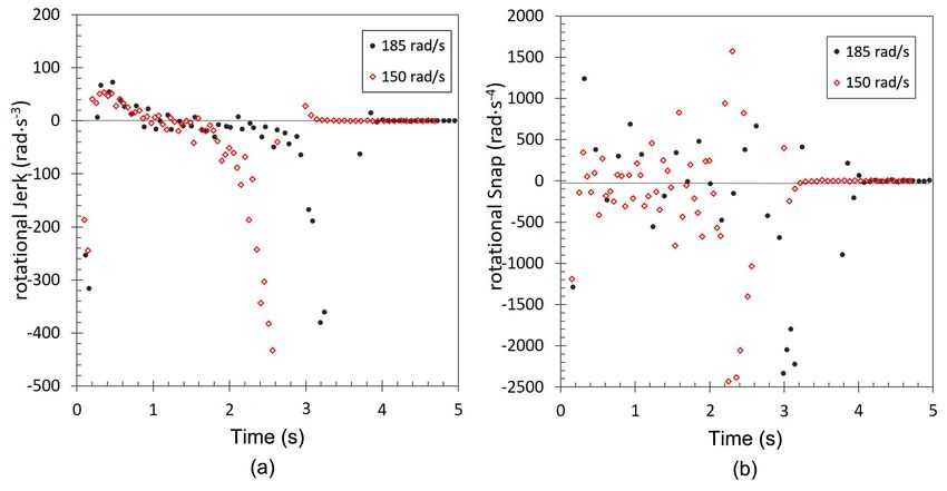
R. P. Turner et al.

                               stored energy of the flywheel [4]. The titanium alloy Ti-6Al-4V is commonly
                               used in the aerospace and aeroengine industries, primarily thanks to its excellent
                               strength-to-weight ratio. As such, Ti-6Al-4V is one of the more commonly stu-
                               died materials within IFW processing [4] [5]. Three distinct phases are com-
                               monly identified during the weld process [5]. Firstly, the conditioning phase sees
                               the components heated at the faying interface by frictional mechanisms. Se-
                               condly, the equilibrium or burn-off phase sees the process force the sacrificial
                               interface material out of the joint, and into the formed flash. Lastly, once the
                               flywheel has exhausted its stored energy, a forging phase consolidates the weld-
                               ing with a small further amount of axial shortening [6].
                                  As such, the process is a highly dynamic manufacturing operation, with the
                               component undergoing rapid rotational displacement caused by the dissipating
                               energy from the flywheel. This rapidly changing energy yields constantly evolv-
                               ing rotational velocity, and as such evolving rotational acceleration, rotational
                               jerk, and higher time-derivatives of rotational position. Whilst the rotational ve-
                               locity, often referred to as the “run-down”, is analysed by manufacturing engi-
                               neers to understand more about the process, the higher derivatives are not. Tita-
                               nium alloys display mechanical property sensitivity to the microstructure and
                               grain size, as well as strain-rate sensitivity [7]. The yield strength of these flow
                               stress curves increases significantly, with the higher strain-rates observed close
                               to the weld line during processing.
                                  However, little work has been considered regarding any potential 2nd, 3rd or
                               higher-order derivative of deformation and in turn any potential material prop-
                               erty sensitivity. It, therefore, remains largely unconsidered and unknown how
                               these properties impact material behavior. If material behavior for the higher
                               orders displays a similar trend to that of the 1st derivative of deformation, then
                               the emerging material mechanical response could significantly vary. Given the
                               relatively small time-steps for which data is saved by the IFW machine analytics,
                               this process does offer a sensible starting position for these higher derivatives to
                               be analysed, using simplistic differential methods using data at the commence-
                               ment and end of each recorded time-step. As such, this paper investigates—at a
                               very introductory level—the higher time-derivatives of rotational displacement
                               to understand if these types of fields can be utilized by industry and academia for
                               a more complete understanding of any characteristics drawn out of the process.

                               2. Material and Methods
                               Ti-6Al-4V hollow axisymmetric cylinders, measuring 80 mm outer diameter, 40
                               mm inner diameter, 86 mm height, were machined from rolled billet. The
                               as-received Ti-6Al-4V displayed the typical duplex α/β microstructure, with
                               globular α-phase interspersed by alternating fine laths of α and β [8]. The ther-
                               mal and mechanical fields experienced by the heated (HAZ) and thermo-me-
                               chanically affected (TMAZ) regions will cause significant microstructure varia-
                               tions [9].
                                  For each weld, two Ti-6Al-4V cylinders were joined using specialist IFW

DOI: 10.4236/aast.2021.62008                        115               Advances in Aerospace Science and Technology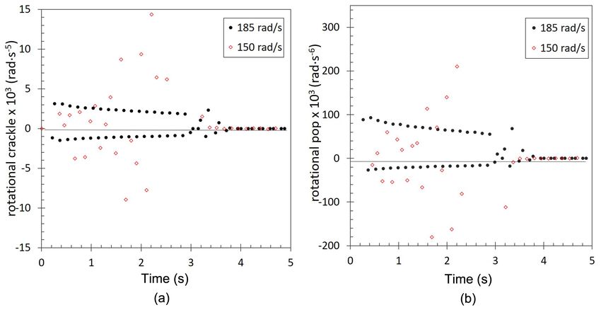
R. P. Turner et al.
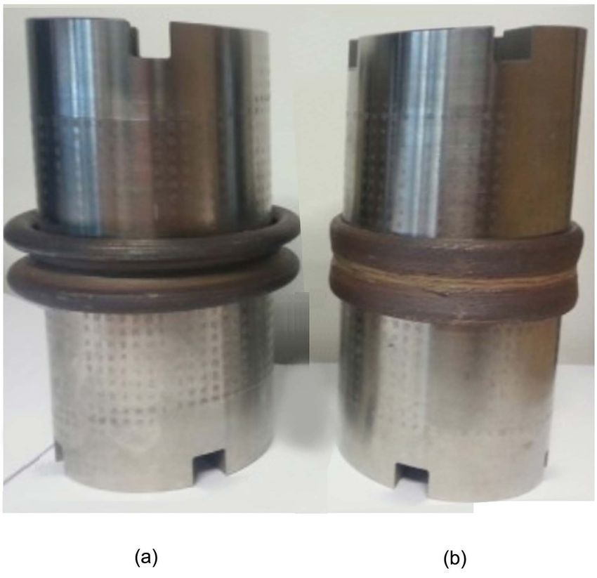
equipment. Welding parameters were selected to produce a successful weld
(Figure 1), allowing for a comprehensive study of rotational acceleration and
higher time-derivatives experienced during manufacture. Two welds were con-
sidered, with identical inertial flywheel mass I, and forging pressure P, but with
different initial rotational speeds, thus different stored energies.
3. Theory
The stored energy available via the flywheel at the start of an inertia welding process
Erot, which gets converted to thermal and mechanical energy, is defined in Equa-
tion (1), whereby I is flywheel inertial mass, and ω is initial rotation speed, in
rad∙s−1.
= 0.5 ⋅ I ω 2
Erot (1)
Two inertia welded samples were analysed, with a “high” stored energy and a
“low” stored energy, as result of a high and low initial rotational velocity. The
inertial mass of the flywheel was held constant, and initial rotational velocities of
185 rad∙s−1 and 150 rad∙s−1 respectively were employed. Due to the square of the
rotational velocity term in the energy equation (Equation (1)), this corresponds
to 1.5E and E as initial stored energies.
In order to calculate the rotational acceleration and higher derivatives, some
simplifications were applied to the rotational velocity data. As instantaneous cal-
culations of these terms, particularly the higher derivative terms, may get very
high, so the data was discretised to consider 0.05 s intervals, and the time-derivatives
of the rotational position were calculated as follows, whereby θ is rotational po-
sition, and so rotational velocity ω ( t ) = dθ dt .
Figure 1. Inertia friction welded Ti-6Al-4V coupons.
DOI: 10.4236/aast.2021.62008 116 Advances in Aerospace Science and Technology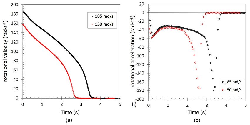
R. P. Turner et al.
rotational acceleration (rad∙s−2); α=
→
( t ) dω dt ≡ f {( d θ ) ( dt )} 2 2
(2)
rotational jerk (rad∙s ); ζ=
−3
( t ) dα dt ≡ f {( d θ ) ( dt )}
→ 3 3
(3)
rotational jounce or snap (rad∙s ); s= ( t ) dζ dt ≡ f {( d θ ) ( dt )}
−4 → 4 4
(4)
rotational crackle (rad∙s ); c =
−5
( t ) ds dt ≡ f {( d θ ) ( dt )}
→ 5 5
(5)
rotational pop (rad∙s ); =
−6
( t ) dc dt ≡ f {( d θ ) ( dt )}
→ 6 6
(6)
The names snap, crackle and pop are informally used by engineers and scien-
tific community [10] to describe the 4th, 5th, 6th derivatives of position. Given that
rotational position has units of radians, so units of the derivative terms in Equa-
tion (2) to Equation (6), are of the form rad∙s−n.
4. Results
4.1. Rotational Velocity and Acceleration
The rotational velocity curves from the two inertia welds were differentiated
multiple times over 0.05 s intervals, to generate the functions for rotational ac-
celeration and higher derivatives. The velocity rundown curve and the rotational
acceleration are presented in Figure 2. The rundown curves from Figure 2(a)
are well-considered amongst Inertia welding engineers, and these illustrate the
gradual decrease over the process, until the last ~0.5 s, when a rapid drop-off of
velocity to zero, indicative of inertia welds, is observed. The rotational accelera-
tion curves are less considered.
Note from the graphs in Figure 2(b) that the same trend is observed, whereby
after the first 0.2s of rotation, in both welds the deceleration is approximately −60
rad∙s−2 and this increases toward approximately −30 rad∙s−2, and then plateaus
for the majority of the process, until the final 0.5 s of the weld when it dramati-
cally shoots toward −180 rad∙s−2, before a sharp change and reducing decelera-
tion toward zero as the stored flywheel energy fully dissipates. Comparing the
Figure 2. (a) rotational velocity versus time curves, and (b) rotational acceleration versus
time curves, for the welds.
DOI: 10.4236/aast.2021.62008 117 Advances in Aerospace Science and TechnologyR. P. Turner et al.
curves in Figure 2(b) it is interesting to note that the levels of local extrema are
surprisingly similar, and the curves mainly differ in the plateau length. This in-
dicates that underlying metallurgical processes governing the initial and final tran-
sients, as well as the steady-state regime, are similar across welds. The only dif-
ference is the amount of energy available to drive the process, which determines
the time-base of the steady-state regime.
4.2. Rotational Jerk and Snap
Similarly, the evolution during the process of rotational jerk, Figure 3(a), and ro-
tational jounce, or snap, Figure 3(b), were analysed for trends. Both welds dis-
play rotational jerk traces in the first 0.2 s at a very negative value, −200 to −300
rad∙s−3, although this rapidly rises to a positive jerk, approximately 50 to 60 rad∙s−3.
For both welds these jerk values gradually decrease through the welding process,
down through zero and in to negative values toward −50 rad∙s−3 at approximate-
ly 0.5 s before the end of the weld. In the last 0.5 seconds, the rotational jerk
spikes to −500 rad∙s−3 before sharply falling to zero.
4.3. Rotational Crackle and Pop
Whilst the data for the rotational jounce, or snap (Figure 3(b)) is much more
randomly spread between −1000 and 1000 for both welds during of the process,
one trend is evident in both data sets. Over the final 0.5 s of welding for each
weld, the rotational snap falls to its greatest negative value, approximately −2500
rad∙s−4, and tends back to zero sharply during the last 0.5 s. As with rotational
acceleration (Figure 2(b)), the main difference in Figure 3(a) and Figure 3(b) is
the time-base of the steady-state regime.
Finally, the highest order time-derivatives of position, the informally-named
crackle and pop terms, were analysed. Time-bases were reduced to 0.1 s for these
terms, to reduce the considerable noise in the differentials. The rotational crackle
is presented in Figure 4(a), and the rotational pop in Figure 4(b). Notice a
Figure 3. (a) Rotational jerk versus time curves, and (b) rotational jounce (or snap) ver-
sus time curves, for the welds.
DOI: 10.4236/aast.2021.62008 118 Advances in Aerospace Science and TechnologyR. P. Turner et al.
Figure 4. (a) Rotational crackle versus time curves, and (b) rotational pop (or snap) ver-
sus time curves, for the welds.
distinct oscillatory pattern in the crackle and pop data for the weld commencing
at 185 rad∙s−1. The weld commencing at 150 rad∙s−1 has been similarly analysed,
although noise in the data has made both the crackle and the pop difficult to de-
termine any trend.
One evident feature across both welds is how dynamic the process is, naturally
undergoing constant changes throughout. Trends from the acceleration and jerk
curves are possibly more intuitive; however the emerging oscillatory trends that
appear evident in the highest derivatives are surprising, especially given the
more scattered data sets for the rotational snap. For both welds examined it is
proposed that initially there was sufficient stored energy to allow the process to
form a dynamic steady state. Toward the end of the process the energy remain-
ing ceases to be sufficient to maintain the dynamic steady-state condition. Thus,
during the last fraction of a second, similar process phenomena occur within both
welds, giving rise to signature trends within the derivative curves, albeit at dif-
ferent times.
It is interesting to observe how the different weld phases show distinctively
different sections within each transient curve, in particular the acceleration and
the jerk curves. The findings provoke further questions surrounding the process.
How would the higher derivative curves appear for poorly chosen welding pa-
rameters, which produce poor welds? How would the curves look for a different
material? These uncertainties would require further investigation and further
experimentation, and are not considered here. However, the derivative study ap-
proach overall does potentially open up a greater opportunity for refined process
control.
5. Conclusions
A study of the time-derivatives, up to the sixth derivative, of rotational position,
has been studied for two Ti-6Al-4V inertia friction welds. After a systematic
analysis of these results, the following conclusions are drawn.
DOI: 10.4236/aast.2021.62008 119 Advances in Aerospace Science and TechnologyR. P. Turner et al.
Rotational acceleration and jerk traces both display clear patterns across the
two welds in terms of behavior of these fields, as the part rotates under action
from the flywheel. The rotational snap also displays a pattern in this deriva-
tive during the final approximately 0.5s of welding, as the energy dissipates.
Evidence of a distinct oscillatory pattern in the rotational crackle and pop
terms was noted for one weld when differentiating over a larger time-base,
though could not be replicated in the 2nd weld, which had no noticeable pat-
tern.
Higher derivative curves allow distinction of different process regimes, indi-
cating that inertial energy mostly influences the time-base of dynamically
steady-state phase. Qualitative differences between initial energies are evident
in higher derivatives.
This novel approach may offer inertia weld specialists, and aerospace engi-
neers who utilize the method, insights toward improving process control,
understanding physical phenomena, or cross-comparisons of welds.
Acknowledgements
We send many thanks to colleagues at the School of Metallurgy and Materials, at
the University of Birmingham, with whom discussions were held, which has held
to shape this exploratory research.
Conflicts of Interest
The authors declare no conflicts of interest regarding the publication of this pa-
per.
References
[1] Li, W., Vairis, A., Preuss, M. and Ma, T. (2016) Linear and Rotary Friction Welding
Review. International Materials Reviews, 61, 71-100.
https://doi.org/10.1080/09506608.2015.1109214
[2] Attallah, M.M. and Preuss, M. (2012) Chapter 2: Inertia Friction Welding (IFW) for
Aerospace Applications. In: Chaturvedi, M.C., Ed., Welding and Joining of Aero-
space Materials, 2nd Edition, Woodhead Publishing, Cambridge, UK.
https://doi.org/10.1016/B978-0-12-819140-8.00002-X
[3] Kallee, S. and Nicholas, D. (1999) Friction and Forge Welding Processes for the
Automotive Industry. SAE. https://doi.org/10.4271/1999-01-3214
[4] Nu, H.T.M, Le, T.T., Minh, L.P. and Loc, N.H. (2019) A Study on Rotary Friction
Welding of Titanium Alloy (Ti6Al4V). Advances in Materials Science and Engi-
neering, 2019, Article ID 4728213. https://doi.org/10.1155/2019/4728213
[5] Turner, R., Howe, D., Thota, B., Ward. R.M., Basoalto, H.C. and Brooks, J.W. (2016)
Calculating the Energy Required to Undergo the Conditioning Phase of a Titanium
Alloy Inertia Friction Weld. Journal of Manufacturing Processes, 24, 186-194.
https://doi.org/10.1016/j.jmapro.2016.09.008
[6] Wang, L., Preuss, M., Withers, P.J., Baxter, G. and Wilson, P. (2005) Energy-Input-
Based Finite-Element Process Modeling of Inertia Welding. Metallurgical and Ma-
terials Transactions B, 36, 513-523. https://doi.org/10.1007/s11663-005-0043-y
[7] Lee, M.-S., Hyun, Y.-T. and Jun, T.-S. (2019) Global and Local Strain Rate Sensitiv-
DOI: 10.4236/aast.2021.62008 120 Advances in Aerospace Science and TechnologyR. P. Turner et al.
ity of Commercially Pure Titanium. Journal of Alloys and Compounds, 803, 711-720.
https://doi.org/10.1016/j.jallcom.2019.06.319
[8] Turner, R.P., Perumal, B., Lu, Y., Ward, R.M., Basoalto, H.C. and Brooks, J.W.
(2019) Modeling of the Heat-Affected and Thermomechanically Affected Zones in a
Ti-6Al-4V Inertia Friction Weld. Metallurgical and Materials Transactions B, 50,
1000-1011. https://doi.org/10.1007/s11663-018-1489-z
[9] Ji, Y., Wu, S. and Zhao, D. (2016) Microstructure and Mechanical Properties of
Friction Welding Joints with Dissimilar Titanium Alloys. Metals, 6, 108-119.
https://doi.org/10.3390/met6050108
[10] Visser, M. (2004) Jerk, Snap and the Cosmological Equation of State. Classical and
Quantum Gravity, 21, 2603-2616. https://arxiv.org/abs/gr-qc/0309109
https://doi.org/10.1088/0264-9381/21/11/006
DOI: 10.4236/aast.2021.62008 121 Advances in Aerospace Science and TechnologyYou can also read


