A14 Cambridge to Huntingdon improvement scheme Environmental Statement Appendices Appendix 3.2: Construction information - Date: December 2014 6.3
←
→
Page content transcription
If your browser does not render page correctly, please read the page content below
A14 Cambridge to Huntingdon
                             improvement scheme

                          Environmental Statement
                                      Appendices
      Appendix 3.2: Construction information

Date: December 2014

6.3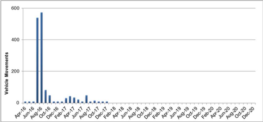
Page left intentionally blank.
A14 Cambridge to Huntingdon improvement scheme           Environmental Statement Appendices

1     Introduction                                                                      1

2     General site operations                                                           2
2.1     Site layout                                                                     2
2.2     Safety and security                                                             3
2.3     Working hours                                                                   3
2.4     Site lighting                                                                   4

3     Construction programme and phasing                                                5
3.1     Construction programme                                                          5
3.2     Section 1 – Alconbury junction to Brampton Hut junction                         5
3.3     Section 2 – A1/A14 Brampton Hut to East Coast mainline railway                  6
3.4     Section 3 – A14 East Coast mainline to Swavesey                                 8
3.5     Section 4 - A14 Swavesey to Girton                                              9
3.6     Section 5 - Girton to A14 Cambridge Northern Bypass                             10
3.7     Section 6 – Huntingdon improvements                                             11

4     Typical construction methods                                                      13
4.1     Utility diversions                                                              13
4.2     Environmental mitigation                                                        13
4.3     Site clearance and demolition                                                   13
4.4     Establishment of construction compounds                                         14
4.5     Enabling earthworks and soil storage areas                                      14
4.6     Borrow pits                                                                     15
4.7     Haul routes                                                                     15
4.8     Earthworks and vehicle movements                                                15
4.9     Staff accommodation and welfare                                                 16
4.10    Road construction                                                               17
4.11    Roadwork finishes                                                               17
4.12    Structures                                                                      17
4.13    Drainage                                                                        18
4.14    Intelligent Transport Systems (ITS)                                             19
4.15    Lighting                                                                        19
4.16    Materials                                                                       19
4.17    Clearance of site on completion                                                 20

6.3                                                                          December 2014
                                                 i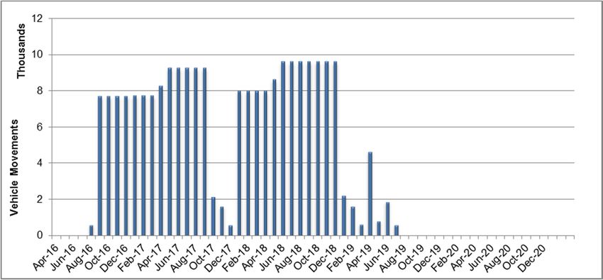
A14 Cambridge to Huntingdon improvement scheme        Environmental Statement Appendices

5     Land requirements                                                              21
5.1     Land required during construction                                            21
5.2     Permanent land                                                               22

6     Public access, site access and traffic management                              23
6.1     Access routes for construction traffic                                       23
6.2     Traffic management requirements                                              23

7     Bibliography                                                                   26

Annex A: Typical plant and machinery – worst case from a noise and vibration
perspective                                                                27

Annex B: HGV movements (construction)                                                36

Annex C: Estimated maximum daily vehicle movements across the scheme 40

6.3                                                                       December 2014
                                                 ii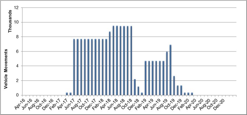
A14 Cambridge to Huntingdon improvement scheme Environmental Statement Appendices
1 Introduction
1.1.1 This appendix provides an overview of the envisaged approach to
construction for the A14 Cambridge to Huntingdon improvement scheme
(the scheme).
1.1.2 The information presented in this appendix has been prepared to provide a
set of assumptions for the purposes of assessing potential construction
impacts as reported and committed to within chapters of the Environmental
Statement (ES).
1.1.3 This appendix has been written during the preliminary design stage of the
scheme’s development. Construction methodology would be subject to
change during the continuing design process until the final design is
complete and main contractors have been engaged. Sufficient contingency
has been added to allow for change. Furthermore, the environmental
assessment of construction impacts within the ES has considered this
uncertainty and incorporated a precautionary approach.
1.1.4 The Rochdale Envelope (PINS Advice Note 9: Using the Rochdale
Envelope) (Planning Inspectorate, 2011) is described as the likely worst
case scenario for the purposes of environmental impact assessment. The
descriptions within this construction information, along with the boundary of
the scheme (as shown on Figure 3.1), has been set out to represent the
likely worst case scenario for environmental assessment using information
available at the time of writing.
1.1.5 Information is set out under the following headings:
general site operations;
construction programme and phasing;
typical construction methods;
land requirements; and
public access, site access, and traffic management.
1.1.6 In addition, Appendix 20.2 of the ES (Code of construction practice) sets
out a series of objectives and measures to be applied throughout the
construction period in terms of management and operation of the works,
environmental protection and limits to disturbance from construction
activities. It also outlines how stakeholders, including both local authorities
and statutory environmental bodies, would be engaged and consulted with
during the construction phase.
6.3 December 2014
1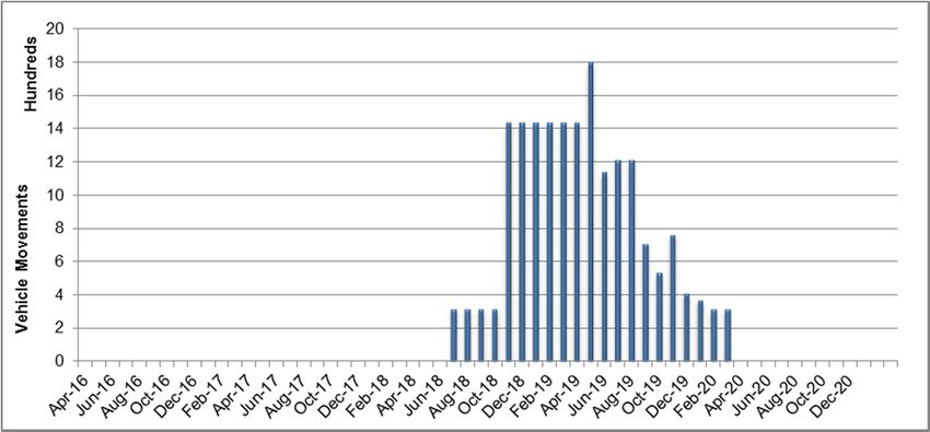
A14 Cambridge to Huntingdon improvement scheme Environmental Statement Appendices
2 General site operations
2.1 Site layout
2.1.1 For construction purposes, the scheme would be divided into six main
areas:
section 1: A1 Alconbury to Brampton Hut;
section 2: A1/A14 Brampton Hut to East Coast mainline railway
(ECML) (including ECML bridge);
section 3: A14 ECML to Swavesey (not including Swavesey);
section 4: A14 Swavesey to Girton;
section 5: Cambridge Northern Bypass; and
section 6: Huntingdon improvements.
2.1.2 Refer to Figure 3.1 for a representation of these sections.
2.1.3 Sections 1 to 5 are all related to the new highway layout and are expected
to be open to traffic by the end of 2019.
2.1.4 Section 6 stands alone both in geographic location and programme. It
comprises the demolition of the existing Huntingdon A14 viaduct and the
connecting of the remaining two ends of the existing A14 into the town’s
local road network.
2.1.5 Each construction section is largely self-contained, either by geographic
barrier, such as the East Coast mainline railway, or by type of construction
activity (on-line or off-line construction).
2.1.6 Taking the general topography of the area, the scheme would involve
substantial earthworks. Where fill material would be required, it has been
designed as far as is practicable to come from within the same section or
from an adjacent borrow pit, ensuring a cut fill balance where local
resources provide the needs of the scheme.
2.1.7 Only where required material cannot be provided from within the scheme
section, either due to insufficient material or the wrong type of material, the
required material would be imported onto the scheme via the existing
strategic road network or potentially via the existing rail network to the
Cambridge railhead and then transferred via local roads.
6.3 December 2014
2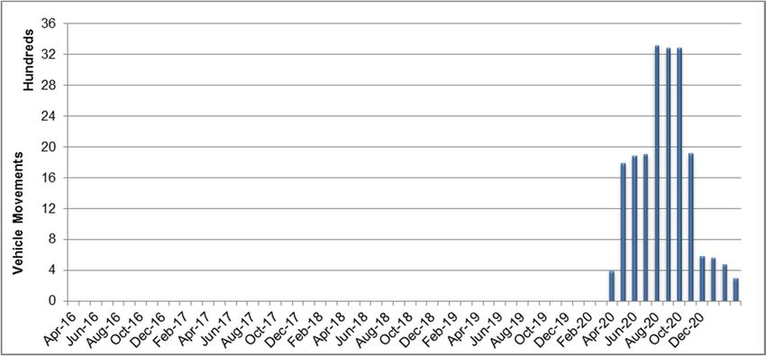
A14 Cambridge to Huntingdon improvement scheme Environmental Statement Appendices
2.1.8 It is envisaged that there would be a need for two batching plants to supply
the construction of the scheme, one each side of the scheme as divided by
the East Coast mainline railway. Facilities would include:
placement of a temporary concrete and asphalt batching plant, as
well as aggregate washing facilities, situated in a compound or
borrow pit within section 2 to supply sections 1 and 2; and
use of an existing batching plant operated by Lafarge at the railhead
in Cambridge to supply the eastern end of the scheme (sections 3, 4
and 5). Material for this location could be brought in by rail when
imported from off-site.
2.2 Safety and security
2.2.1 Appendix 20.2 of the ES (Code of construction practice) sets out a number
of safety issues that the contractor would need to consider which include
but are not restricted to:
working adjacent to built-up areas;
working in, over or adjacent to watercourses including the river
Great Ouse;
working on or adjacent to public roads, footpaths or cycle tracks or
in proximity to live traffic;
working over or adjacent to railways;
working at height;
undertaking electrical works;
working over or adjacent to, or diverting statutory undertakers’ plant;
and
handling contaminated materials.
2.2.2 The construction site, compounds and storage areas would be secured
from public access.
2.3 Working hours
2.3.1 Working hour constraints are specified in the Appendix 20.2 of the ES
(Code of construction practice).
2.3.2 In summary, the typical core working hours for the scheme are expected to
be between 08:00 and 18:00 on weekdays (excluding bank holidays) and
from 08:00 to 16:00 on Saturdays. In addition there would be a start-up
and close down period of one hour either side of these times to maximise
efficiency of the core hours. This would include activities such as
deliveries, movements to work, maintenance and general preparation
works, but not include running plant and machinery that are likely to cause
a disturbance to local residents or businesses.
2.3.3 It is expected that core hours of working would be followed within the
scheme borrow pits and for the majority of the offline sections 2 and 3.
6.3 December 2014
3A14 Cambridge to Huntingdon improvement scheme Environmental Statement Appendices
2.3.4 Where there are live running lanes adjacent to the site, the online sections
of the new alignment (1, 4 and 5) would likely require extended night time
working to facilitate traffic management moves, installation of signs and
technology, bridge construction and surface tie-ins.
2.3.5 Due to the complexity of operations associated with section 6, 24 hour
working would be required to maximise the short duration of railway
possessions over the East Coast mainline railway.
2.3.6 Seasonal construction activities such as earthworks could be subject to an
application for extended hours working to make best use of the season.
The expected extended working hours would cover 07:00 to 08:00 and
18:00 to 20:00 during week days. All non-core working patterns would
require consent via a section 61 agreement under the Control of Pollution
Act 1974.
2.3.7 Repairs or maintenance of construction equipment (other than emergency
repairs) would typically be carried out outside of core working hours,
normally on Saturday afternoons (13:00 to 18:00) or on Sundays between
09:00 and 17:00.
2.4 Site lighting
2.4.1 Site lighting would generally be required as follows:
provision of lighting for contractor’s compounds for security and safe
movement of staff during winter mornings and evenings;
provision of road lighting along temporary access roads;
provision of temporary road lighting to maintain at least an
equivalent level of lighting where there is existing lighting in place
prior to construction;
provision of temporary road lighting where there is currently no
lighting, as lighting is required as a safety measure under temporary
traffic management; and
provision of task lighting required for night time activities or winter
afternoon activities, such as installation of bridge beams.
2.4.2 Maintenance of road lighting at locations where the layout is to be changed
would be provided by early commissioning of permanent new lighting where
feasible, powered by generators, if necessary. Where this is not feasible
lighting may be provided by mobile lighting towers or by use of columns in
temporary locations.
6.3 December 2014
4A14 Cambridge to Huntingdon improvement scheme Environmental Statement Appendices
3 Construction programme and phasing
3.1 Construction programme
3.1.1 The construction of sections 1 to 5 of the scheme would be programmed to
take four years to complete, with works commencing in 2016. Sections 1 to
5 are programmed to be open to traffic by late 2019. Section 6, including
the demolition of the Huntingdon A14 viaduct, would be undertaken once
the Huntingdon southern bypass is operational.
3.1.2 On the above basis, the envisaged construction programme is as shown in
Table 3.1.
Table 3.1: Proposed construction programme
Scheme section Start Completion
1 – A1 Alconbury to Brampton Hut 2016 2017
2 – A1/A14 Brampton Hut to ECML 2017 2019
3 – A14 ECML to Swavesey 2017 2019
4 – A14 Swavesey to Girton 2016 2019
5 – A14 Cambridge northern bypass 2018 2019
6 – Huntingdon viaduct demolition 2020 2021
3.1.3 Within the construction sections of a scheme of this size, construction
would be phased so to accommodate enabling works and to facilitate
construction logistics such as ensuring efficient working around traffic
management restrictions on the online sections. In addition, it is possible
that some minor enabling works, such as habitat establishment, may be
undertaken in advance of 2016. This detail would be completed during the
detailed design stage of the scheme.
3.1.4 Phased construction starts within sections which would avoid
environmentally sensitive locations until such time that essential mitigation
had been carried out.
3.1.5 Whilst the programme in Table 3.1 sets out the phased construction
programme envisaged at the preliminary design stage, it should be noted
that the ES topic assessments of construction impacts have generally
assumed that construction would take place concurrently across the
scheme in order to represent a worst case scenario. The topic specific
approach to the construction assessment is set out in Chapters 8 to 17 of
the ES.
3.2 Section 1 – Alconbury junction to Brampton Hut junction
3.2.1 The works are between Alconbury junction and Brampton Hut junction and
comprise parallel widening of the A1 from two lanes to three lanes as well
as the introduction of a single carriageway local access road connecting the
new Ellington junction with Woolley Road (access to Huntingdon Life
Sciences).
6.3 December 2014
5A14 Cambridge to Huntingdon improvement scheme Environmental Statement Appendices
3.2.2 Cut and fill balance can be achieved within section 1 as the earthworks
materials required can be wholly obtained from borrow pit 7 and local
floodplain compensation areas.
3.2.3 Phase 1 of section 1 construction works would entail site and route
establishment comprising the following:
borrow pit 7 (located on the western side of A1) and two-way haul
route from borrow pit 7 to east side of the A1 would be established
early on in the programme;
the off-line section would be fenced as a construction site;
permanent fencing would be used where possible; and
protection works/diversions would be carried out over the Oil
Pipeline Agency high pressure oil pipeline, as well as all utilities
diversions and culvert construction running concurrently.
3.2.4 Phase 2 of section 1 would entail the construction of the new A1
southbound carriageway and local access road, comprising the following:
construction of the new three lane southbound carriageway would
commence offline, to the east of the existing A1. Construction of the
local access road would be undertaken concurrently; and
drainage, technology and concrete barrier works would be carried
out throughout the earthworks and pavement construction.
3.2.5 Phase 3 of section 1 would be made up of widening the existing
southbound carriageway, comprising the following:
the existing southbound carriageway would be widened creating the
new northbound carriageway; and
drainage and technology works would be carried out concurrently.
3.2.6 Phase 4 of section 1 would be construction of the local access road tie in
points to Woolley Road and Ellington Junction. These would be completed
during the construction of Ellington junction, likely to be during the later
stages of the construction programme.
3.3 Section 2 – A1/A14 Brampton Hut to East Coast mainline railway
3.3.1 Section 2 comprises a new A1 alignment to the west of the current A1, with
a portion of the new A14 utilising the current A1 alignment. Two new slip
roads would enable connections between the A1 and A14. The works
within this section are largely offline.
3.3.2 There are four main structures which would need to be built early in the
programme. These include the A14 over A1 structure, the northbound slip
road over A1, the Grafham Road bridge and a temporary bridge over the
river Great Ouse.
3.3.3 It is expected that a cut-and-fill balance can be achieved for section 2 as
the earthworks material required can be obtained from borrow pits 1 and 2
as well as a proportion of fill from the floodplain compensation areas within
section 1 and to the east of the river Great Ouse in the south of section 2.
6.3 December 2014
6A14 Cambridge to Huntingdon improvement scheme Environmental Statement Appendices
3.3.4 Phase 1 of section 2 construction works would entail site and route
establishment comprising the following:
protection works/diversions would be carried out over the Oil
Pipeline Agency high pressure oil pipeline, with all utilities diversions
and culvert construction running concurrently;
construction fencing would be installed, permanent where possible;
the establishment of borrow pits 1 and 2, along with compounds and
soil storage sites would be early activities;
the establishment of a concrete and asphalt plant would be required
in this section, probably within one of the borrow pits, to ensure
material demand is met later in programme; and
haul routes along the new A1 and offline A14 section would be
created.
3.3.5 Phase 2 of section 2 would entail further concurrent construction made up
of the following:
construction of the critical structures within this section, particularly
the temporary bridge over the river Great Ouse to enable
construction vehicles to cross; and
the following works would be carried out concurrently:
o construction of the new A1 offline route (three lanes in either
direction) to the west of the existing A1;
o the realignment of Buckden Road bridge requiring the
creation of an underpass;
o A14 offline section (not including Ellington junction) to the
river Great Ouse, and then to the East Coast mainline railway
once the temporary bridge is constructed;
o construction of the Great Ouse viaduct, beginning with the
earthworks and foundation construction; and
o construction of the East Coast mainline railway bridge.
3.3.6 Phase 3 of section 2 comprises construction of the new A14 and would
involve the following:
once the new A1 is constructed, traffic from the existing A1 would be
switched onto the new alignment allowing works to commence on
the existing A1 which would become the new A14;
as the A14 section from Ellington junction to the northern ends of
the slip roads is two lanes in each direction, mainly resurfacing
works would be required (no widening); and
concurrently, major earthworks would need to be moved from
borrow pit 2 to the proposed noise bund on the east side of the
existing A1.
6.3 December 2014
7A14 Cambridge to Huntingdon improvement scheme Environmental Statement Appendices
3.3.7 Phase 4 of section 2 would involve the construction of Ellington junction, as
follows.
Ellington junction would be constructed enabling the Huntingdon Life
Sciences local access road to be completed. These works would
not be conducted until sections 2 and 3 of the main scheme have
been completed; and
the temporary bridge over river Great Ouse would be removed and
remediation works to borrow pits 1 and 2 would begin once the A14
was open to traffic.
3.4 Section 3 – A14 East Coast mainline to Swavesey
3.4.1 Section 3 would consist of predominantly offline construction, apart from
where structures meet existing local roads.
3.4.2 This section has a cut-and-fill balance as the earthworks to the west of the
A1198 are predominantly in cut and those to the east of the section
requiring fill, with additional fill requirements met by borrow pit 3 and three
floodplain compensation areas.
3.4.3 This section is predominantly phased due to the logistics of moving
engineering fill past logistical blockers such as the construction of the
Ermine Street junction. Road construction itself would follow earthworks in
the phases as described below.
3.4.4 Phase 1 of section 3 construction works would entail site and route
establishment comprising the following:
prioritisation of site establishments around the Ermine Street
junction. Also establishment of borrow pit 3, compounds and soil
storage sites across the section;
haul routes to the west of A1198 would be established along the
new highway alignment; and
utilities diversions and culvert construction would run concurrently.
3.4.5 Phase 2 of section 3 would comprise the construction of Ermine Street
junction and concurrent works made up of the following:
construction of the Ermine Street junction would begin early,
enabling a haul route along the trace of the offline section over the
A1198. It is expected that the bridge making up the junction
structure would be prefabricated offsite as far as practicable to
increase the speed with which the construction would take place;
concurrently, movement of fill material from borrow pit 3 and the
floodplain compensation areas to the fill areas to the east of A1198
would be carried out; and
commencement of the other structures along this section would start.
6.3 December 2014
8A14 Cambridge to Huntingdon improvement scheme Environmental Statement Appendices
3.4.6 Phase 3 of section 3 comprises further earthworks movements, as follows.
following the Ermine Street junction construction, a haul route would
be built enabling the soil storage at Ermine Street junction to be
shifted across to the east side of A1198, with the majority of fill
being used for earthworks from Ermine Street junction to the
approximate location of borrow pit 3; and
landscaping in the form of planting trees/hedges on bunds and other
areas would be carried out once earthworks were complete.
3.4.7 Phase 4 of section 3 would entail the construction of the tie-in points at Fen
Drayton and Ellington junctions.
3.5 Section 4 - A14 Swavesey to Girton
3.5.1 Section 4 comprises asymmetric (Swavesey – Bar Hill) widening from two
to three lanes, and symmetric widening (Bar Hill – Girton) from three to four
lanes. The works are largely online (mainly the symmetric widening
section). A complex arrangement of traffic management would be required
on this section due to live traffic running; in addition, several utility
diversions would be required.
3.5.2 The section also includes the reconfiguration of Girton interchange,
including a new A14 westbound slip road as well as the realignment of the
A428 and tie-in to the new local access road.
3.5.3 Section 4 has a shortage of fill material which it is expected would be met
from the adjacent borrow pits 5 and 6.
3.5.4 Phase 1 of section 4 construction works would entail site establishment
comprising the following:
borrow pits 5 and 6 sites would be established as well as section
wide haul routes;
in terms of earthworks, in order to minimise haulage across the A14,
borrow pit 5 would supply earthwork fill requirements south of the
A14 and borrow pit 6 north of the A14 where possible to minimise
any disruption to the running A14 traffic; and
utilities diversions and culvert construction would run concurrently.
3.5.5 Phase 2 of section 4 would consist of online widening construction works
(asymmetric and symmetric), as follows:
There are two distinct widening configurations within section 4,
asymmetric widening (Swavesey junction to the Bar Hill junction)
and symmetric widening (Bar Hill junction to Girton junction). Both
would be carried out with the likely implementation of section wide
traffic management in order to ensure efficient traffic flows and safe
working.
Girton junction has both online and offline elements which would be
carried out concurrently. A428 diversions as well as new A14
westbound slip roads can be built offline with tie-in points and
resurfacing works to follow.
6.3 December 2014
9A14 Cambridge to Huntingdon improvement scheme Environmental Statement Appendices
asymmetric widening would involve:
o the construction of a new offline three lane northbound
carriageway and central reserve to the south of the existing
A14;
o with traffic switched to the new alignment, a new southbound
carriageway would be constructed by widening the existing
northbound carriageway; and
o lastly, works would begin on the new local access road by
widening and resurfacing the existing southbound
carriageway where needed.
concurrent symmetric widening works would involve:
o construction works in the central reserve requiring traffic
management to be employed, most likely in the form of
narrow lane running; and
o once complete, narrow lanes would still be utilised within the
traffic management, moving running traffic towards a new
central reserve in order to enable the widening works on the
outer edge of both carriageways to begin.
3.6 Section 5 - Girton to A14 Cambridge Northern Bypass
3.6.1 Section 5 would comprise online widening on the north side between the
Histon and Milton junctions.
3.6.2 A Highways Agency ‘pinch point’ scheme between Girton and Histon
junctions, widening the road from two to three lanes, began construction in
mid-April 2014 and is scheduled to be complete in mid-December 2014.
The pinch point works are not considered part of this scheme.
3.6.3 Section 5 requires fill material from borrow pit 6.
3.6.4 Phase 1 of section 5 construction works would entail site establishment
comprising the following:
establishment of a section wide haul route with borrow pit 6 having
been established within section 4;
no utility diversions have been identified for section 5; and
it is assumed the existing railhead in Cambridge would be
commissioned prior to construction works as a means to bring in
materials for the whole scheme.
3.6.5 Phase 2 of section 5 would entail further concurrent construction made up
of the following:
carriageway widening from two lanes to three lanes on the northern
side from Histon to Milton junctions; and
road wagons with a carrying capacity of approximately 12m3 (20
tonnes) would be utilised for fill material movements to the required
areas between Histon and Milton junctions.
6.3 December 2014
10A14 Cambridge to Huntingdon improvement scheme Environmental Statement Appendices
3.7 Section 6 – Huntingdon improvements
3.7.1 Once the new A14 is constructed and open to traffic, the process of de-
trunking the works within Huntingdon would begin.
3.7.2 Decommissioning of the viaduct over the East Coast mainline railway would
not begin until new infrastructure is in operation and certain remodelling
works within Huntingdon have been completed.
3.7.3 The works would involve a number of railway possessions being booked in
advance which is likely to be over the Christmas/New Year period. These
possessions would facilitate the installation and removal of a temporary
access/protection deck for Brampton bridge.
3.7.4 The dismantling of the viaduct is complex and would require specialist
contractors with specific large plant for lifting, processing and transporting.
3.7.5 Below is the general phasing for removal of the viaduct over the East Coast
mainline railway and remodelling works in Huntingdon. Activities would be
concurrent with a focus on maintaining all accesses and the continued use
of Brampton bridge.
Demolition of viaduct over East Coast mainline railway
3.7.6 Phase 1 on the section 6 demolition works would comprise the installation
of a temporary protection deck under the A14 viaduct. This would require a
rail blockade and a series of possessions on the East Coast mainline prior
to construction.
3.7.7 Phase 2 works would consist of temporary works and demolition as per the
following:
a temporary bridge would be installed across the section span;
construction of temporary supports, followed by the removal of the
viaduct surfacing, concrete topping and abutments for the section
directly over the railway;
removal of box beams and the central section of the viaduct, as
well as the removal of ramps and temporary bridge; and
demolition of the outer approach spans leaving two unconnected
sections still standing in isolation for phase 3.
3.7.8 Phase 3 works would consist of the installation of temporary slide platforms:
erection of temporary slide platforms and load collars adjacent to the
still standing viaduct supports;
transfer of the load onto the collars, then demolition of the
supporting piers; and
sliding of the remaining viaduct sections away.
3.7.9 Phase 4 would involve the removal of the temporary access/protection deck
structure.
6.3 December 2014
11A14 Cambridge to Huntingdon improvement scheme Environmental Statement Appendices
Town centre remodelling works
3.7.10 Phase 1 of the town centre remodelling works would involve construction of
the Pathfinder Link. This would be in advance of the demolition works on
the viaduct. Construction of the Pathfinder Link from the ring road to the old
A14 embankment would be completed initially.
3.7.11 Phase 2 would be construction of the temporary station access to involve
the following:
Once the central section of the viaduct is removed, a temporary
access into Huntingdon railway station would be formed from
excavated material from the south-east approach (not to be the
finished road level as the demolition programme at this stage does
not allow enough time for excavation and paving to be completed to
finished level). This would require some temporary earthworks on
the southern station approach.
Access to the station would need to be in place before work over the
existing station access road from Brampton Road is carried out.
3.7.12 Phase 3 works would incorporate construction of the Views Common link
road, as follows:
whilst the eastern demolition works are underway, work would begin
on the Views Common link road; and
the roundabout at the western end of the section would be
completed when the removal of the western elements of the viaduct
are complete, however the earthworks could be completed in
advance of this.
3.7.13 Phase 4 works would incorporate the Mill Common link road, as follows:
The excavation of the Mill Common link road from the northern
station junction to the temporary station access would be
undertaken concurrently with the demolition of the eastern abutment.
It would be during this phase that the Brampton Road junction could
also be completed.
Once space is opened out and the bridge piers have been removed,
the northern end of Mill Common link road could be completed and
opened to allow access into the station. At this point, the temporary
access would be closed and works completed to bring the rest of the
Mill Common link road to the finished road level, along with the
southern Station junction. This section would be the last to be
completed and opened.
6.3 December 2014
12A14 Cambridge to Huntingdon improvement scheme Environmental Statement Appendices
4 Typical construction methods
4.1 Utility diversions
4.1.1 There are a number of utility diversions that would form part of enabling
works in advance of, or are integrated into, the construction of the scheme.
These include diversion or protection work upon the assets of:
Oil Pipeline Agency high pressure oil pipeline;
Fibre-optic cables operated by British Telecom and Virgin Media;
UK Power Networks infrastructure;
Cambridge Water and Anglian Water infrastructure; and
National Grid gas networks.
4.1.2 For the purposes of this assessment, all utility diversions are considered as
part of the scheme.
4.1.3 The makeup of the utility diversion works are of a similar nature to those of
initial elements of the road construction in that they would involve localised
site clearance, excavations and back fill for underground services and
standard civil engineering practices for overhead lines.
4.1.4 The exception to the standard utility diversions would be the high pressure
pipelines within the scheme footprint that require licenced and specialised
contractors to work with high pressure apparatus.
4.1.5 The works diverting underground services would involve either directional
drilling apparatus or open trench work as appropriate within the programme
of construction works at any one particular location.
4.1.6 Overhead services would be either diverted but retained overhead, or
diverted by burying underground.
4.2 Environmental mitigation
4.2.1 The environmental mitigation measures for the scheme are detailed
throughout the ES and summarised within Appendix 20.1 and Appendix
20.2 of the ES.
4.2.2 Environmental mitigation would be carried out in advance of construction
sites being established in sensitive areas of the scheme. The construction
programme would be phased to accommodate mitigation within sensitive
areas before construction commenced in those places.
4.2.3 Some environmental mitigation would run concurrently with the construction
of the scheme where practicable and within the constraints of applicable
licences and permit consents.
4.3 Site clearance and demolition
4.3.1 Annex A shows the worst case plant and machinery that would be used for
site clearance.
6.3 December 2014
13A14 Cambridge to Huntingdon improvement scheme Environmental Statement Appendices
4.3.2 Off-line sections would be cleared of vegetation during daytime working
hours. On-line sections would be cleared during night time with traffic
management if required, according to Highways Agency network
occupancy guidelines.
4.3.3 All arisings would be taken off-site. No fires would be permitted within the
scheme footprint.
4.3.4 Properties for demolition within the scheme footprint would be stripped of
recyclable material before being flattened using heavy plant machinery with
waste being transported off-site.
4.4 Establishment of construction compounds
4.4.1 An indicative location of the scheme construction compounds are shown on
Figure 3.1.
4.4.2 After environmental mitigation and site clearance, typically the
establishment of construction compounds would involve the following
activities:
defining the boundary using fencing or temporary noise bunding;
soil stripping, placing and compacting stone for compound base;
setting up drainage as required, including perimeter drainage;
creating access tracks with bound material surfacing if required;
setting up power requirements including generators;
setting up offices, welfare facilities and wheel washing; and
installation of security/access gates.
4.4.3 The plant used for this operation would be typical of that for road
construction as described in Annex A.
4.4.4 Compounds are expected to accommodate office and welfare facilities,
plant and machinery parking, storage facilities, maintenance areas and
workshops, and on-site temporary residential premises.
4.4.5 It is anticipated that, where practicable, compounds would be returned to
the previous land use after decommissioning.
4.5 Enabling earthworks and soil storage areas
4.5.1 To meet with the construction programme for the scheme, it is anticipated
that enabling earthworks would commence in the spring of 2016 on
sections 1 and 4.
4.5.2 Topsoil would be stripped from all surfaces subject to construction. Topsoil
would be stored in designated soil storage areas according to a soil
management plan to be referred to in Appendix 12.2 of the ES. Locations of
indicative soil storage areas are shown on Figure 3.1.
4.5.3 The type of earth moving plant to be used within the scheme is listed in
Annex A.
6.3 December 2014
14A14 Cambridge to Huntingdon improvement scheme Environmental Statement Appendices
4.5.4 It is anticipated that soil storage areas would be returned to the previous
land use once the storage is no longer required.
4.6 Borrow pits
4.6.1 The various borrow pits within the scheme would be established in a similar
way as the construction compounds described above.
4.6.2 Following site clearance, the site boundary would be fenced and security
gates installed at the site entrance to prevent unauthorised access. Topsoil
and subsoil layers would be stripped and stored around the perimeter of the
site to buffer local receptors from the operations within the borrow pits and
minimise the transportation of material around the scheme. In general,
topsoil stored closest to boundary would be up to 2m high and
subsoil/overburden behind this would be up to maximum of 3m high.
4.6.3 Access tracks would be constructed, along with any infrastructure to be
sited within the boundary as per the construction compounds.
4.6.4 Interception drains would be installed to prevent excessive ingress of
surface water into the workings. Suitable surface water settlement ponds
would be created to prevent the contamination of nearby surface
watercourses with sediments and suspended solids.
4.6.5 It is anticipated that the borrow pits in gravel strata (particularly in section 1)
would require a form of active de-watering when extracting material below
the standing water level. The precise method of de-watering would depend
upon the contractor, but it is anticipated that the contractor would create
well points, install a vertical barrier around excavations and directly install
pumps at the bottom of the excavation.
4.6.6 Borrow pit 5 would be expected to return to agriculture across the majority
of the footprint. Part of borrow pit 6 would also return to agriculture. Re-
use of the available topsoil from the soil storage areas would be used to
enable this.
4.6.7 The remaining borrow pits would be restored to create a variety of
ecological habitats, wetland areas, mixed grasslands, woodland planting
and for informal recreation purposes. Refer to Appendix 3.3 of the ES for
further detail on borrow pit restoration.
4.7 Haul routes
4.7.1 Dedicated haul routes are identified on the scheme and can be seen within
Figure 3.1. As well as the new haul routes shown, the route alignment on
the off-line sections would be used as a main haul route during the
construction phase.
4.7.2 Where on new alignments, temporary haul routes would be created by
stripping the topsoil and replacing with capping material to create a hard
standing surface suitable for heavy goods and off-road vehicles.
4.8 Earthworks and vehicle movements
4.8.1 It is not anticipated there would be any requirement for blasting on this
scheme.
6.3 December 2014
15A14 Cambridge to Huntingdon improvement scheme Environmental Statement Appendices
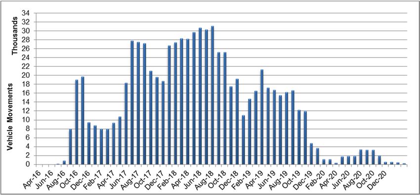
4.8.2 The phased construction programme described above has been cross-
referred with the material requirements of the scheme to provide a monthly
programme of predicted earthworks quantities and main scheme
construction activities (road construction, structures and demolition).
Vehicle movements throughout the programme and across the phases of
the six construction sections of the scheme have been calculated
accordingly. To represent the likely worst case scenario, vehicle
movements have all been qualified as heavy goods vehicle (HGV)
movements
4.8.3 At this preliminary design stage, a contingency of 10% additional fill
material has been incorporated across the programme to account for
unknown factors associated with earthworks. Also, a contingency of
between 10% and 35% additional HGV movements has been incorporated
to account for deliveries (such as gantries, communications equipment,
bridge beams). The level of contingency applied was determined on the
basis of professional judgement having regard for the section of the works
and the uncertainty in number of vehicle movements to deliver specific
components.
4.8.4 The expected daily and monthly HGV movements across the scheme are
presented within Annexes B and C.
4.8.5 For the earthworks aspect of the scheme, typical earth moving vehicles
would be either articulated dump trucks for site movements, capable of
carrying 20m3 of material (approximately 35 tonnes), or tipper trucks for
both site and on-road movements of material, capable of carrying 12m3
(approximately 20 tonnes). The appropriate type of vehicle has been
accounted for in calculating the estimated vehicle movements associated
with each section of the scheme.
4.9 Staff accommodation and welfare
4.9.1 It is anticipated that a likely worst case peak labour force of between 2,000
and 2,750 could be employed on the scheme during the busiest three years
of construction. It is estimated that a peak of 500 employees would live on
site during the second, third and fourth years of construction.
4.9.2 Accommodation, offices, welfare (canteen and washing facilities), fleet
parking and storage depots are expected to be located within compounds
already described. Temporary buildings would make up the infrastructure
of the compounds during operation. Typically these would be made up of
portable modular units typical of large construction sites. Some buildings
would be stacked one on top of the other for efficiency of space within the
sites. The maximum stack would be expected to be two modular units high.
4.9.3 It is expected that all soil storage areas would have welfare facilities within
them. Where the distance between soil storage areas is too great for the
number of workforce in a particular location, mobile welfare vans would be
on site to minimise journeys by the workforce.
4.9.4 All proposed compounds and soil storage areas are located within close
proximity of the scheme alignment, which would help to lower traffic to and
from site once depot plant and personnel are installed within compounds.
6.3 December 2014
16A14 Cambridge to Huntingdon improvement scheme Environmental Statement Appendices
4.9.5 It is expected that the majority of the workforce would arrive on site via the
strategic road network, avoiding local access roads where practicable.
4.10 Road construction
4.10.1 Pavement construction involves building the pavement up in layers. A
typical road construction would be:
35mm thin surfacing;
55mm binder course;
85mm upper base;
200mm lower base; and
280mm stabilised sub base.
4.10.2 The bottom layer (sub-base) is a crushed rock aggregate which would be
delivered to the site via the strategic road network or by rail and then
transferred from the Cambridge railhead using the local road network. The
material is deposited and then pushed into place and compacted.
4.10.3 The upper pavement layers would be made up of bituminous material. All
of these would require the transport of bituminous material to the site either
from the local batching plant at the Cambridge railhead or from a temporary
batching plant on site.
4.11 Roadwork finishes
4.11.1 Following pavement construction, vehicle restraint systems (VRS) or safety
barriers would be installed. There are various types of Highway Agency
approved VRS models available. In the central reserve, vehicle restraint
barriers would predominately be constructed of extruded concrete on site.
Steel vehicle restraint systems would be employed along the verge lengths,
parapets and bridge connections. Steel barrier installation would involve
driving steel posts into the ground or excavating small footings and placing
concrete into which the posts are set. The barriers are either bolted or
strung to the posts and fixed to small concrete anchorages.
4.11.2 Sign installation would involve excavation for the foundations, poured
concrete and then setting the posts. The sign faces are then fixed to the
sign posts. Some signs may be lit and would require cabling to be passed
through service ducts.
4.11.3 Road markings would be sprayed onto the road surface using specialist
lorry mounted equipment. This is a mobile operation with zero waste
material from the thermoplastic paint mixture used.
4.12 Structures
4.12.1 The scheme would involve construction of 30 new bridges (Appendix 3.1 of
the ES), adding to the 31 existing bridges of which 14 are being adapted,
13 are being retained as unaffected and four being demolished (including
the Huntingdon A14 viaduct in section 6).
6.3 December 2014
17A14 Cambridge to Huntingdon improvement scheme Environmental Statement Appendices
4.12.2 Structure locations are available on Figure 3.1. Structure visualisations are
part of the cross sections found within Figure 3.3.
4.12.3 A standard pattern of work for an A14 bridge would include:
bored piling;
pouring concrete foundations;
formwork and pouring concrete to form piers and abutments to hold
up the bridge deck;
laying down prefabricated bridge beams by crane;
building the bridge deck, waterproofing; and
dressing the bridge with parapets, barriers and a blacktop
bituminous layer.
4.12.4 All bridge beams would be precast or prefabricated offsite and brought in by
road. There is a potential exception for the A14/A1 Link overbridge which
has an option to be built by poured concrete in situ.
4.12.5 It should be assumed there would be up to an average of one month of
bored piling work at each new structure. Exceptions to this are at the river
Great Ouse viaduct and the wide structures at Girton and the A14/A1
interchange. At these locations, it is assumed four months of bored piling
for the former and two months bored piling for the latter are realistic.
4.12.6 Bridge deck beams would all be either pre-cast concrete or pre-fabricated
steel and would be transported to site by road. For the largest structures,
some of these would be significant vehicles carrying 30-40m concrete
bridge beam sections. Steel sections would be likely to be shorter and
bolted together to meet wider spans in situ. There would be careful
planning with regards the routing of these loads, avoiding sensitive routes
where practicable.
4.12.7 Specific to the bridge over the East Coast mainline railway, works would
include the accommodation and modification of existing overhead line
equipment including localised portal gantry installation either side of the
bridge to facilitate the construction of the new structure over the railway
line.
4.13 Drainage
4.13.1 Culverts (Appendix 3.1 of the ES), headwalls, outfalls, pipes, ironworks and
manhole rings would be precast offsite and brought in by road.
4.13.2 It is envisaged that numerous sheet piling operations would take place for
temporary works/ground support for excavations during drainage
installation. Modern sheet piling techniques do not necessarily require
percussive plant use, although this might remain an option in open spaces
with no sensitive receptors close by and where the ground conditions do
not permit alternatives.
6.3 December 2014
18A14 Cambridge to Huntingdon improvement scheme Environmental Statement Appendices
4.13.3 Extruded concrete lined drainage channels would be set down either side of
the highway and poured on site with concrete coming from batching plants
at either end of the scheme to minimise concrete import onto the scheme.
4.13.4 Balancing ponds and swales would make up part of the earthworks
element.
4.14 Intelligent Transport Systems (ITS)
4.14.1 Amongst the assets within the ITS criteria for the scheme are superspan
gantries, motorway signal mark 3 (MS3) and motorway signal mark 4 (MS4)
type gantries (all gantries may either carry variable message signs or
standard highway signs, but a similar gantry structure would be used
regardless), closed circuit television (CCTV) masts, communications
cabinets, traffic detection loops within the road surface, and the required
ducting to carry cables between assets.
4.14.2 The larger sign structures typically involve the installation of portal or
cantilever gantries/message signs. The construction sequence normally
starts with construction of concrete foundations, followed by installation of
the gantry legs. The gantries themselves would be fabricated off-site and
lifted in by crane. The electrical equipment is then connected and
commissioned. A full gantries schedule is provided in Appendix 3.1 of the
ES.
4.14.3 The assumed weight of steel within the prefabricated structures are taken
as:
MS3: 10 tonnes (cantilever message signs);
MS4: 5 tonnes (cantilever message signs); and
Superspan of 20m: 30 tonnes (portal gantry).
4.14.4 Longitudinal cabling involves minor engineering work for trenching,
installation of cables and construction of drawpits and cabinets. Cross
carriageway ducts are installed for connection of equipment in the central
reserve. Traffic detection loops are cut into the completed carriageway
surface.
4.15 Lighting
4.15.1 Lighting would be restricted to junctions. Lighting columns would be of
highways standard. Columns would be transported via the road, expecting
to use the existing strategic road network to arrive on site and then navigate
via the haul routes to in-situ locations.
4.15.2 Cabling can be assumed to be as with ITS services.
4.16 Materials
4.16.1 The raw materials required for the scheme include primary aggregates,
particularly sand and clay. The scheme is located over existing areas of
gravel, sand and clay and as such, material from the existing area would be
used where practicable.
6.3 December 2014
19A14 Cambridge to Huntingdon improvement scheme Environmental Statement Appendices
4.16.2 Construction, demolition and excavation wastes would also be considered
as an alternative to primary aggregates.
4.16.3 The appropriate quantities of particular materials that would be required by
the scheme are identified in Table 4.1.
4.16.4 At this preliminary design stage, there is a degree of uncertainty about
material volumes and their sources. In order to ensure the assessment of
likely significant effects from the likely worst case scenario during
construction, all material volumes quoted include a contingency of 10%.
4.16.5 The likely worst case comprises of imported major material types being
blacktop, concrete and steel. Aggregates would be sourced from borrow
pits and cuttings within the scheme boundary.
4.16.6 To cover uncertainty in the source locations of imported materials, it is
assumed that up to 14% of the total materials required for the scheme
would be imported (incorporating the contingency of 10%) in respect of
construction vehicle movements accessing the scheme from offsite.
Table 4.1: Estimated material quantities
Construction material required Estimated quantities of materials (m3)
Blacktop 516,700
Sub base 273,040
Capping 383,700
Concrete 606,370
Steel 12,360
Plastics 2,765
4.17 Clearance of site on completion
4.17.1 Clearance of the soil storage and compound sites upon completion of the
works would normally involve small dumpers, excavator/loaders and lorries
to gather up and dispose of surplus material and return the ground to the
condition in which it was found.
6.3 December 2014
20A14 Cambridge to Huntingdon improvement scheme Environmental Statement Appendices
5 Land requirements
5.1 Land required during construction
5.1.1 Land required during construction may be in addition to that required for the
footprint of the permanent works. The main requirements are described
below. All land required for temporary use within the construction of the
scheme is within the DCO boundary submitted as part of the DCO
application.
Site compounds
5.1.2 Where possible site compounds would be located close to the proposed
works where there is suitable access. Site compounds would be used to
accommodate offices for the contractors as well as workshops, stores,
welfare facilities, worker accommodation and parking for vehicles and plant
machinery. Refer to Figure 3.1 for indicative locations of site compounds.
Haul routes
5.1.3 Although the majority of the scheme’s haul routes would utilise either
existing highway due to the proximity of the borrow pits to the scheme, or
existing tracks, some land would be required to enable access to the
permanent works. Haul routes and access arrangements are shown on
Figure 3.1.
Borrow pits
5.1.4 Owing to the requirement for fill within the scheme, six borrow pits have
been identified for providing a combination of aggregate and capping as
required by the scheme. The borrow pits have been allocated per scheme
section limiting the need to transfer material from one end of the scheme to
the other.
Floodplain compensation areas
5.1.5 Areas have been identified within the flood risk assessment modelling to
provide lower ground to compensate for areas of the floodplain lost to the
scheme. Floodplain compensation areas for the scheme are represented
on Figure 3.2.
Soil storage areas
5.1.6 Soil storage areas have been identified on Figure 3.1. It is envisaged the
majority of these areas would return to previous use.
Temporary diversions
5.1.7 In order to maintain traffic flows when undertaking works on the existing
highway such as a new bridge or carriageway tie-ins, it may be necessary
to provide a temporary diversion.
6.3 December 2014
21A14 Cambridge to Huntingdon improvement scheme Environmental Statement Appendices
5.2 Permanent land
5.2.1 The main requirements for permanent land are as follows:
land taken by the earthworks required to accommodate the
permanent new highway alignments, i.e. land required to build
embankments or excavate cuttings;
land required to allow adequate drainage of the road and the area
through which it passes. This includes land required for diversion of
watercourses, drainage outfalls and mitigation features such as
attenuation ponds and pollution control units, including
arrangements for maintenance access; and
land required for other environmental mitigation such as
landscaping, planting and screening.
5.2.2 Other land not required for the permanent works may be permanently
acquired by the Highways Agency due to it becoming unusable or
impractical to use as a direct result of the works or because of
commitments given in the planning of the scheme.
5.2.3 For greater detail on land requirements, refer to the Statement of Reasons,
DCO document reference 4.1.
6.3 December 2014
22A14 Cambridge to Huntingdon improvement scheme Environmental Statement Appendices
6 Public access, site access and traffic
management
6.1 Access routes for construction traffic
6.1.1 The construction works are generally accessible from the strategic road
network so most construction vehicle movements would be able to use
these main routes. The contractor would be restricted as to the extent and
purpose of using other roads for construction purposes. While it is
desirable for all construction related access to be via the major routes it
would be necessary to provide some other access for isolated construction
areas. These additional routes would be determined in consultation with
the relevant local roads authority. Where necessary signage would be
provided on roads to indicate that the route is not to be used by the
contractor.
6.2 Traffic management requirements
6.2.1 During construction, temporary traffic management would be required to
undertake the works whilst minimising disruption to users of both the
existing mainline and the local side road network.
6.2.2 In general, construction phasing and temporary traffic management
proposals would be prepared on the basis of keeping the same number of
lanes in use as existing during the peak periods of traffic flow. Lane
closures would be employed during off-peak times for the facilitation of
changes to traffic management, surfacing tie-ins and gantry or bridge
construction.
6.2.3 For the main routes, it is expected that traffic would be kept on the normal
carriageways wherever possible, if necessary using narrow lanes and
restricted temporary speed limits through the main works areas.
6.2.4 It is expected that other routes including slip roads at major junctions would
be kept open during construction of the new works. This would, in some
cases require construction of extensive temporary alignments. The
proposals would be prepared on the basis of keeping all routes and
accesses open throughout the works.
6.2.5 As well as planning the traffic management proposals to limit wherever
practicable road-user delays, the safety of vulnerable road-user groups
such as pedestrians and cyclists would be a particular consideration.
Works restrictions
6.2.6 It is generally proposed that the network connection works would be
constructed within the typical working hours as set out in this appendix with
no requirement or intention for prolonged late night or 24 hour working.
The only exceptions to this would be for the installation of gantries and
beams on new bridges which could only be carried out during an overnight
closure of any live carriageways being spanned, along with some surfacing
activities. Alternative diversion routes would be set up during such night
time closures, together with advance warning and publicity to help drivers
to avoid these locations/dates if possible.
6.3 December 2014
23A14 Cambridge to Huntingdon improvement scheme Environmental Statement Appendices
6.2.7 Some further restrictions such as reducing through traffic to one lane may
be applied in order to carry out critical tie-in works between existing and
new carriageways and gantry erection. This would minimise the number of
road closures and diversions required. Weekend or night time road
closures would be programmed to avoid significant local or national events
that might generate substantial increases in traffic. All closures and
diversions would require a temporary traffic order and be subject to
approval by the Highways Agency, Police and maintaining authority.
6.2.8 If contra-flows were to be adopted for certain sections of the online
construction, additional temporary lighting would, if necessary, be provided
at cross-over points. Temporary lighting would also be required where
construction would be undertaken during night time periods, for example
during tie-in surfacing work.
Temporary or permanent road closures or diversions
6.2.9 Temporary road closures and diversions would be arranged following
discussions with the relevant highways authority, police and the maintaining
agents. A temporary traffic order giving the requisite notice would be
prepared and a statutory notice placed in local newspapers.
6.2.10 Temporary road closures that occur as a consequence of the phasing for
the construction of new alignments would be implemented following
discussions with relevant parties and agreement of temporary traffic
arrangements for the next phase of the works.
6.2.11 The traffic management for the scheme would follow the guidance in the
Road Works and Temporary Situations Chapter (Chapter 8) of the Traffic
Signs Manual (Department for Transport, 2009), adopting the following
standards as applicable:
where heavy vehicles, including public service vehicles are
expected, the lane width may be reduced to 3.25m (desirable) or
3.0m (absolute minimum). Lane widths of 3.25m and 3.0m would
therefore be used with an appropriate reduction in the speed limit
where two narrow lanes have to be maintained. A minimum lane
width of 3.5m would be adopted where possible; and
a minimum lateral clearance of 1.2m between two-way traffic where
temporary steel safety barrier is used, particularly, when the speed
limit is 50mph and a minimum lateral clearance of 0.5m between
two-way traffic when the speed is 40mph or below.
Signage
6.2.12 Provision of signage at junctions in the vicinity of contra-flow arrangements
should allow drivers to determine the lane destinations prior to entering the
contra-flow, thus reducing the amount of late lane changes.
6.3 December 2014
24You can also read