Acousto-optic systems for advanced microscopy - IOPscience
←
→
Page content transcription
If your browser does not render page correctly, please read the page content below
TOPICAL REVIEW • OPEN ACCESS

Acousto-optic systems for advanced microscopy
To cite this article: Martí Duocastella et al 2021 J. Phys. Photonics 3 012004

View the article online for updates and enhancements.

                                This content was downloaded from IP address 46.4.80.155 on 04/01/2021 at 12:03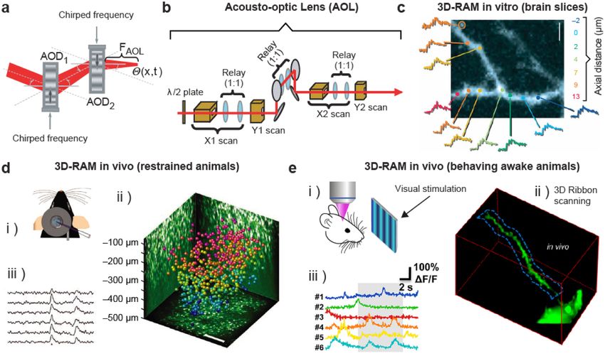
J. Phys. Photonics 3 (2021) 012004 https://doi.org/10.1088/2515-7647/abc23c
Journal of Physics: Photonics
TOPICAL REVIEW
Acousto-optic systems for advanced microscopy
OPEN ACCESS
Martí Duocastella1,2, Salvatore Surdo2, Alessandro Zunino2,3, Alberto Diaspro2,3 and Peter Saggau2,4
RECEIVED 1
24 June 2020 Department of Applied Physics, Universitat de Barcelona, C/Martí i Franquès 1, 08028, Barcelona, Spain
2
Nanoscopy, CHT Erzelli, Istituto Italiano di Tecnologia, Via Enrico Melen 83, Building B, 16152, Genova, Italy
REVISED 3
7 August 2020 Department of Physics, University of Genoa, Via Dodecaneso 33, 16146, Genova, Italy
4
Department of Neuroscience, Baylor College of Medicine, Houston, TX, United States of America
ACCEPTED FOR PUBLICATION
15 October 2020 E-mail: marti.duocastella@ub.edu and psaggau@bcm.edu
PUBLISHED
Keywords: acousto-optics, optical microscopy, high-speed imaging, advanced volumetric microscopy
24 November 2020
Original content from
this work may be used Abstract
under the terms of the
Creative Commons Acoustic waves in an optical medium cause rapid periodic changes in the refraction index, leading
Attribution 4.0 licence. to diffraction effects. Such acoustically controlled diffraction can be used to modulate, deflect, and
Any further distribution focus light at microsecond timescales, paving the way for advanced optical microscopy designs that
of this work must
maintain attribution to feature unprecedented spatiotemporal resolution. In this article, we review the operational
the author(s) and the title
of the work, journal principles, optical properties, and recent applications of acousto-optic (AO) systems for advanced
citation and DOI. microscopy, including random-access scanning, ultrafast confocal and multiphoton imaging, and
fast inertia-free light-sheet microscopy. As AO technology is reaching maturity, designing new
microscope architectures that utilize AO elements is more attractive than ever, providing new
exciting opportunities in fields as impactful as optical metrology, neuroscience, embryogenesis,
and high-content screening.
1. Introduction
Cornerstones in developing new optical technologies are systems capable of directly controlling light. Efforts
in this direction have led to transformative advances in both research and industry, ranging from optical
fibers for communication [1] to complex optical traps for laser cooling [2]. Among these technologies,
advanced optical microscopy showcases the success of developing innovative strategies for guiding, focusing,
splitting, and modulating light. Here, the optimal control of light directly determines the amount of
information that can be retrieved from a sample. As such, modern microscopy architectures have come hand
in hand with novel methods to increase speed, precision, and resolution at which light can be focused onto
and collected from a sample. For instance, laser-scanning microscopes such as confocal [3] or multiphoton
[4] systems—presently the tool-of-choice for cellular and functional tissue imaging—have flourished thanks
to methods for precisely and swiftly scanning a focused laser beam across a sample. Similarly, the growing
interest of light-sheet and structured-illumination microscopes (SIMs) [5] in the life sciences is mostly due
to new approaches for shaping light beams [6, 7]. All in all, improvements in light control have radically
changed optical microscopes, rendering them quantitative tools for characterizing living specimen with
unprecedented spatial and temporal detail.
Several approaches exist to control illumination and detection of light in optical microscopes. They can
be broadly divided into two groups: passive and active systems. The first group includes lenses, beam
splitters, and diffractive optical elements, producing a static output for a given light input. While quality and
customization has improved thanks to modern fabrication technologies such as three-dimensional (3D)
printing of optical components [8, 9], their operational principle and implementation have remained largely
unchanged. The second group, active systems, is capable of dynamically shaping light, and has seen a
tremendous progress over the last decades. Examples include, spatial light modulators for multi-point
illumination [10] and adaptive optics for reduction of aberrations [11], resonant scanning mirrors for
reduced photobleaching [12], varifocal systems for fast axial focusing [13], and electro-optical scanners for
fast imaging [14] and 3D particle tracking [15]. Among active systems, the family of acousto-optic (AO)
devices stands out because of its versatility. AO devices enable high-speed modulation, deflection, splitting,
© 2020 The Author(s). Published by IOP Publishing Ltd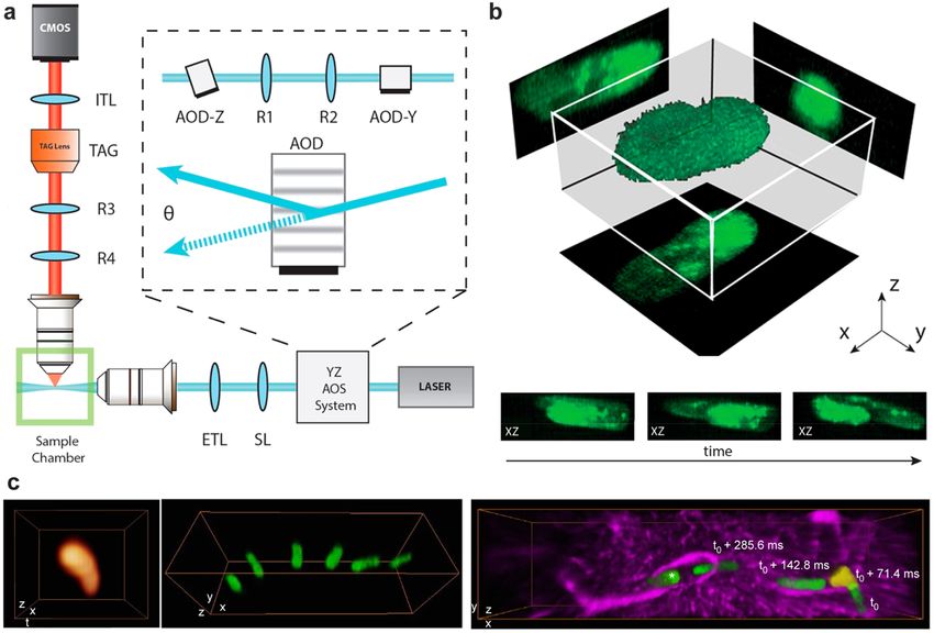
J. Phys. Photonics 3 (2021) 012004                                                                                   M Duocastella et al

   Figure 1. Acousto-optic Effect. (a) Interaction of light with an ultrasound wave: a piezoelectric actuator generates an acoustic
   wave that periodically modulates the refractive index of a medium. A light wave upon traversing the vibrating region is diffracted
   into one or multiple beams. The operating regime depends on the properties of both light and the vibrating medium, as
   summarized in parameter Q. (b) Raman–Nath regime: when Q ≪ 1, diffraction pattern consists of multiple beams separated by
   angles θm . The resulting light pattern is symmetrical around the undiffracted beam (m = 0). (c) Bragg regime: when Q ≫ 1, and
   incident angle equals the Bragg angle θB , only a single beam is diffracted at the incidence angle.

filtering, and focusing of light. These features, combined with their ease of implementation, have rendered
them essential components of advanced optical microscopes.
     In this review, we provide a comprehensive introduction to AO systems and their applications to optical
microscopy. First, we describe the operation principles and properties of various AO devices, emphasizing
the differences between members of the AO family and their early use in optical microscopes. Next, we
survey recent developments in advanced microscopy that feature AO devices as enabling elements, including
random-access scanning microscopes and fast volumetric imaging systems. They provide clear examples of
the numerous possibilities that AO systems offer in imaging applications. Finally, we discuss how AO devices
can help to continue shaping the present and future of optical microscopy.

2. How acousto-optic systems work

The large family of AO devices provides a complete toolkit for controlling light in microscopy applications,
ranging from splitting to focusing beams as well as amplitude and frequency modulation. Despite the
significant differences between AO devices, they all operate under the same physical principle, the so-called
AO effect. This phenomenon consists of the diffraction of light by ultrasound waves [16]. Briefly, ultrasound
is used to create regions of compression and rarefaction in an optical medium, which in turn, produce local
changes in the refractive index (figure 1(a)). For typical AO materials (crystals and liquids) and ultrasound
intensities, the maximum change in refractive index (∆n) ranges from 10−4 to 10−5 . When a beam of light
propagates through such an acoustically perturbed medium, it undergoes a phase transformation, resulting
in singular diffraction effects.
    Depending on the properties of the vibrating medium (static refractive index n0 , thickness L, speed of
sound cs ), the wavelength of light (λ), and the frequency of ultrasound (f), two different regimes can be
identified leading to distinct diffraction patterns. While no sharp transition exists between them, it has
proved useful to identify the two regimes by the parameter Q [17], defined as:

                                                                  2πλLf 2
                                                            Q=                                                                          (1)
                                                                   n 0 cs 2
    The parameter Q quantifies the effective thickness of the vibrating medium. Depending on the
magnitude of Q, two distinct diffraction phenomena are possible. When Q ≪ 1, known as the Raman–Nath
regime, the diffraction pattern consists of a fan of beamlets symmetrically spread with respect to the
undiffracted beam (zero order). As shown in figure 1(b), each beamlet is diffracted at a fixed angle
θm = mλf/n0 cs , and experiences a frequency shift mf, where m is an integer denoting the diffraction order.
Thus, an AO device operated in this regime acts as a moving thin phase grating [18]. Although the splitting of

                                                       2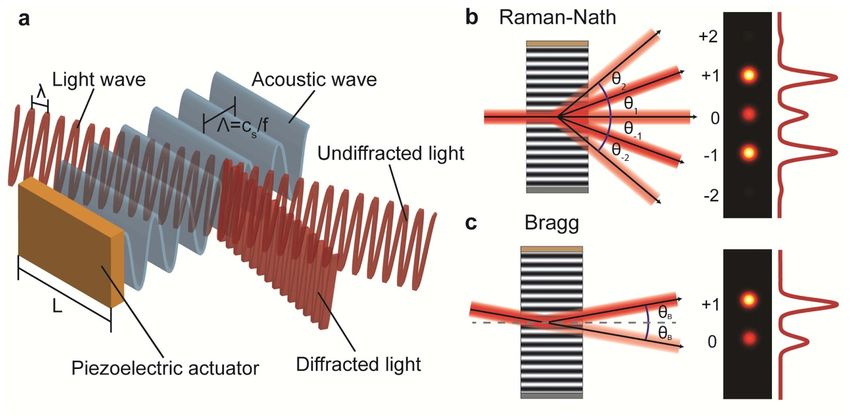
J. Phys. Photonics 3 (2021) 012004                                                                   M Duocastella et al

light into multiple beams forming an optical frequency comb is of great interest in microscopy, it comes with
a caveat. The intensity of each beamlet is different, rapidly decaying for higher orders, and never reaching
more than the 34% of the incident intensity. However, as detailed in the next sections, new AO devices used
in microscopy for fast axial focus control or generating interference patterns do operate in this regime.
    When Q ≫ 1, known as the Bragg regime, the diffraction pattern typically contains a single diffraction
order. For this to occur, the incident beam needs to enter the AO device at a particular angle, called the Bragg
angle θB , given by the expression:

                                                   sin θB = λf/2n0 cs                                               (2)

     As shown in figure 1(c), such a condition, known as phase- or momentum-matching, leads to the
deflection of the diffracted beam by an angle equal to θB , with a frequency shift of the light wave of ±f
depending on the sign of the incident angle. Hence, the Bragg regime is optically equivalent to a moving thick
phase grating. Notably, the beam diffracted after the AO device maintains most of the incident intensity, with
typical maximum values in the range of 60%–100%. Such a high diffraction efficiency facilitates the
integration of AO devices in optical microscopes as add-on modules (no need to increase the illumination
power). It also helps to design systems for controlling light in different directions by cascading multiple
AO devices.
     The previous description, although general, does not provide a complete picture of the AO effect.
Additional aspects need to be considered when selecting or designing an AO device for microscopy. Among
them, the type of ultrasound waves—longitudinal or transverse and traveling or standing—is essential. In
general, AO devices make use of longitudinal waves. However, transverse waves are preferred in specific
applications such as beam deflection at high spatial resolution. Traveling waves are prevailing in most AO
devices, particularly in those operating at the Bragg regime. In this case, besides the ultrasound generator, the
AO device needs to incorporate an acoustic absorber at the opposite side to prevent unwanted sound
reflections that may reduce the intensity of the diffracted beam. The main advantage of traveling waves is a
continuous operating frequency band. Alternatively, standing waves are generally used with Raman–Nath
diffraction. Because a resonant cavity is needed here that may be susceptible to temperature fluctuations,
feedback systems are required to maintain the diffraction pattern at the discrete resonant conditions. Note,
though, that diffraction generated by standing waves depends on time. Therefore, once steady-state is
reached, it is possible to select different light patterns at high speed—only limited by the driving frequency
[19]. Resonance also allows for minimal driving power of the ultrasound actuators.
     The optical anisotropy of the medium also plays a pivotal role in AO devices, with direct consequences
for microscopy applications. By using birefringent materials, the incident and diffracted angles are no longer
the same. Thus, the range of incident beam angles, or the operative frequency bandwidth of AO devices can
be significantly increased [20]. As detailed in the following section, most AO deflectors and all AO tunable
filters use birefringent materials. Particularly, uniaxial crystals, exhibiting a crystal axis with a refractive index
different from the other two. As a result of the anisotropy of these materials, careful attention must be paid to
the polarization direction of both incident and diffracted beams relative to the orientation of the AO device.
Thus, additional optical elements, such as adjustable waveplates, are normally required to successfully
integrate AO devices into microscopes.

2.1. Types of acousto-optic devices
The need for optimizing the many facets of light control has spurred the development of an entire family of
AO devices. They all operate under the same principle and also feature the same key elements, including an
AO medium transparent to light, an ultrasound source (normally a piezoelectric transducer), and the control
electronics. The latter enables adjusting frequency and amplitude of the driving signal, and consequently, the
ultrasound waves and the diffraction regime. Because all AO devices achieve light control without the inertia
of moving mechanical components, they have typical response times well below milliseconds. Despite these
similarities, each AO device has distinct characteristics suitable for performing a specific task, as briefly
summarized in table 1. Understanding these characteristics is vital for microscopy applications, where strict
requirements exist regarding focusing precision and photon collection efficiency [21]. Next, we detail the
main features of a selected number of AO devices that are relevant for advanced microscopy.

2.1.1. AO modulators
One of the most widely used AO devices in microscopy is the acousto-optic modulator (AOM). It is a
common component in laser-scanning microscopes, including confocal or two-photon systems, for elegant
electronic control of the illumination intensity. It is also used for generating a synchronization signal and for
laser pulse picking. In all these applications, the AOM acts as a high-speed light attenuator.

                                               3
J. Phys. Photonics 3 (2021) 012004 M Duocastella et al
Table 1. Types of acousto-optic devices. Top to bottom: acousto-optic modulator (AOM), acousto-optic deflector (AOD), acousto-optic
tunable filter (AOTF), acousto-opto-fluidic (AOF) device, and tunable acoustic gradient (TAG) lens.
Device Regime Function Main features Cautionary remarks
Bragg Optical attenuator Contrast Speed/efficiency
Rise time: 5–500 ns trade-off
Bragg Angular scanner Angular range: 1–50 mrad Speed/resolution
Resolution: 5–500 spots trade-off
Bragg Wavelength selector Bandwidth: 0.1–50 nm Efficiency up to 90%
Tuning time: 1–10 µs
Raman–Nath Pattern generator Tunability Diffracted beams are
Speed: 0.1–10 MHz not independent
Raman–Nath Varifocal lens Optical power: 0–10 m−1 Sinusoidal scanning
Speed: 0.01–1 MHz
AOMs consist of a piezoelectric actuator bonded to a facet of a rectangular solid medium—typically a
birefringent crystal or fused silica. As shown in table 1, AOMs are operated in the Bragg regime at a fixed
driving frequency (40–200 MHz range), producing the splitting of an incident beam into two beamlets at a
fixed angle. By tuning the sound amplitude, the relative intensity between the two beamlets can be
modulated. Although both beamlets can be used for light modulation, the diffracted beam is usually
preferred in microscopy. The latter grants high contrast between the minimum and maximum light
intensity—from no light to about 70% of the incident light, given by the typical diffraction efficiency of
AOMs. A central aspect of AOMs is their high-modulation speed, determined by the time to reach the
maximum or minimum values of the diffracted light (rise and fall time). For a Gaussian beam of size w, the
rise time is related to the acoustic access time τ, namely the time the ultrasound wave needs to traverse the
light beam:
τ ∝ w/cs (3)
Thus, an AOM typically features a small aperture, which requires it to be placed between two lenses, one
for focusing and one for re-collimation of the beam. Using this strategy, the diffraction efficiency is reduced,
but the benefit is a decrease in modulation time, down to tens of nanoseconds.
2.1.2. AO deflectors
Acousto-optic deflectors (AODs) are AO devices optimized to function as fast electronic beam scanners
(see table 1). They are implemented in advanced laser-scanning systems to maximize the laser deflection
speed, and consequently, the spatiotemporal resolution retrieved from dynamic samples [22]. They are also
used to shift the frequency of the incident beam by a controlled amount. In this case, they are also known as
acousto-optic frequency shifters (AOFS).
AODs share many resemblances with AOMs regarding design, geometry, and operational mode (Bragg
regime). However, some singular and important differences exist. In AODs, beam scanning is obtained by
tuning the driving frequency—the angle of the diffracted beam (Bragg angle) depends on this parameter
(see equation (2)). Thus, an electronic driver capable of operation over a wide frequency range is needed.
Blocking of the undiffracted beam is also required. Importantly, to maintain a high diffraction efficiency over
a broad angular range ∆θd , AODs normally make use of birefringent materials. As previously described, for a
fixed angle of incidence, the phase-matching condition only occurs at a given acoustic frequency.
Birefringent materials, operated around the so-called tangential phase-matching, allow overcoming this issue
and achieve an extended frequency band ∆f, typically of 50 MHz or above.
4J. Phys. Photonics 3 (2021) 012004 M Duocastella et al
In microscopy, maximizing ∆f is not only crucial to achieve a high ∆θd , but also to increase the number
of resolvable focal spots N, defined as:
N = τ ∆f (4)
where τ is the acoustic access time (see equation (3)). Notably, due to unavoidable beam divergence,
resolution increases with beam diameter. Consequently, AODs commonly have an aperture much larger than
AOMs. An aspect to consider is that both N and ∆θd are larger for materials featuring a low speed of sound.
Therefore, resolution and scanning range come at the cost of sacrificing speed: the response time of AODs is
up to 4 orders of magnitude slower than AOMs, and within hundreds of microseconds. Still, AODs are
amongst the fastest beam steering devices. It is also worth noting that the large acoustic bandwidth of AODs
allows driving them with a multifrequency signal. In this case, each harmonic component diffracts the
incident beam at its corresponding Bragg angle, resulting in an array of independently controlled beamlets.
2.1.3. AO tunable filters
Acousto-optic tunable filters (AOTFs) are AO devices that operate as electronically adjustable
narrow-band-pass filters [23]. They are typically implemented in the beam-combining unit of laser-scanning
systems to control intensity and wavelength of multiple laser lines. They can also be used as fast tunable
beam splitters for multi-color imaging [24, 25].
AOTFs, similarly to AODS, also operate in the Bragg regime, exhibit a rectangular geometry, use
birefringent crystals, and require electronic drivers with a wide frequency range. Indeed, by changing the
driving frequency, the central wavelength λc of the passband that fulfills the phase-matching condition
varies as:
cs ∆n
λc = (5)
f
where ∆n is the birefringence of the crystal. Critical parameters for selecting an AOTF in microscopy are the
spectral resolution ∆λ and wavelength scan rate. Commercial AOTF can have a ∆λ as narrow as one
nanometer or below. The scan rate, defined as the time needed to switch between beam wavelengths,
depends on the acoustic access time, with typical values of a few microseconds.
A particular feature of AOTFs is the possibility to be implemented in the detection arm of a microscope
for precise spectral imaging. Note, though, that the loss of light passing through the device, even if only 10%,
is not ideal for fluorescence systems, in general having a low photon budget.
2.1.4. AOF device
Acousto-optofluidic devices (AOFs) function as electronic beam shapers to generate tunable optical patterns.
They can be used for increasing imaging speed in laser-scanning systems or for producing light patterns in
super-resolution techniques such as SIM.
In contrast to the AO devices previously described, AOFs consist of a liquid-filled chamber containing
two pairs of orthogonally oriented piezoelectric actuators. Each actuator pair forms an acoustic resonant
cavity. When driven on resonance, they produce ultrasound standing waves that diffract an incoming beam
into an array of beamlets. Thus, the direct construction of 2D beam arrays is possible when both cavities are
operative [26]. Interestingly, by adding a focusing lens between the device and the objective lens, the
beamlets interfere, generating 3D patterns in the focal plane of the objective [19]. Note, although the latter is
also possible with AODs, unavoidable crystal defects can deteriorate the pattern quality [27]. AOFs are
operated at the Raman–Nath regime—as the significant acoustic attenuation of liquids at high frequencies
makes it challenging to reach the Bragg regime. As such, AOFs offer a wide acceptance angle for the incident
light, which eases alignment procedures and facilitates integration in microscopy systems.
The main features of AOFs are their high tunability and speed. By controlling the frequency and
amplitude of the driving signal, the properties of the diffraction pattern, such as the number, spacing, and
intensity of the diffraction orders, can be selected with the only constraint that the diffracted beams are not
independent from each other. Also, the use of standing waves offers an extra control parameter. Employing
synchronized pulsed illumination, the temporal phase difference between light pulses and the ultrasound
wave enables to select a diffraction pattern faster than the acoustic access time. Given typical operation
frequencies in the 0.5 − 5 MHz range, AOFs can operate at a timescale below 1 µs.
2.1.5. TAG lens
Tunable acoustic gradient (TAG) lenses are AO devices operating as fast varifocal lenses. They are typically
used in microscopy to extend the depth-of-field of high numerical aperture (NA) objective lenses, and as fast
5J. Phys. Photonics 3 (2021) 012004 M Duocastella et al
axial scanners for high-speed volumetric imaging. Under certain conditions, they can also be used to
generate Bessel beams [28–31].
TAG lenses have a cylindrical geometry, unique within the family of AO devices. They consist of a
piezoelectric tube filled with a liquid. When driven on resonance, an ultrasound standing wave is formed,
which can be described with a Bessel function [32]. Typically, a TAG lens requires the illumination beam
clearly underfilling its aperture, in order to remain smaller than the central lobe of the Bessel function. In this
mode, a TAG lens acts as a parabolic gradient-index lens, with the optical power δ (t) that periodically varies
over time [29]:
1 Lna ω 2
δ (t) = = sin (ωt) (6)
Flens (t) 2cs 2
where Flens is the focal length of the lens, L is the length of the tube, ω the angular driving frequency, and na is
a constant that depends on ω and the liquid properties. The normal frequency range of a TAG lens is between
50 kHz and 1 MHz, and thus falls in the Raman–Nath regime. The effective NA of a TAG lens is low—as the
aperture is limited by the central lobe of the Bessel function. Thus, for microscopy applications, TAG lenses
are always used in combination with high NA objectives. By placing the TAG lens in a conjugate plane of the
back focal plane of a microscope objective, magnification effects can be avoided, and the lens enables fast
z-focus scanning. Such continuous z-focusing at microsecond time scales is faster than the integration time
of many optical detectors. In this case, the simultaneous collection of multiple focal planes leads to an image
with virtual extended depth-of-field. Notably, if synchronized stroboscopic illumination or fast detectors
with appropriate electronics are used, information from multiple axial positions can be acquired.
When illuminated with a beam larger than the central lobe of the Bessel function, the TAG lens acts as an
axicon with a user-selectable cone angle [32]. In this case, a Bessel-like beam is formed. Such a beam is of
interest in microscopy, particularly in applications where fast interrogation of a volume without the need for
axial resolution is required, as in some aspects of neuroimaging.
3. Recent applications of acousto-optic systems for advanced microscopy
The enormous advantages that AO devices offer regarding fast control of light have previously been utilized
in microscopy. However, their use was limited to a small number of niche applications, such as laser power
control (AOMs) and fast filters (AOTFs). With the advent of new technologies, including fast optical
detectors, electronics, and digital acquisition cards, new opportunities for the use of AO devices in
microscopy have emerged. Here we provide examples of how novel schemes, designed around AO devices,
can help to enhance the performance of optical microscopes, allowing us to characterize relevant dynamic
events at unprecedented spatiotemporal resolution.
3.1. Fast z-scanning volumetric microscopy
Maximizing the amount of spatial and temporal 3D-information retrieved from a sample is crucial in
scientific and industrial applications ranging from cell imaging to optical inspection. Typically, 3D
microscopes operate by acquiring a z-stack, namely a sequence of optical sections at different focal planes.
Such a strategy requires techniques capable of optical sectioning, that is the virtual slicing of a sample into
2D sections [5]. In addition, the focus position must be axially translated. Unfortunately, fast z-focus
scanning, a key factor in determining the overall volumetric imaging speed, has been technically challenging.
Even today, most state-of-the-art 3D microscopes feature piezoelectric actuators for z-focusing via sample or
objective lens translation. Due to inertia, the z-scanning rate is limited to a maximum of about 100 Hz. Thus,
the z-axis has traditionally been the slowest scanning axis in a microscope system, imposing a burden when
imaging fast dynamic processes. The implementation of AO systems, in particular the TAG lens, into 3D
microscopes has helped to change this paradigm, effectively overcoming the restrictions in z-scanning speed.
3.1.1. Non-synchronized z-scanning
By conjugating the TAG lens to the back-aperture of a microscope objective lens, continuous z-focus
scanning is attained at microsecond timescales. Such speed is faster than the exposure time or pixel dwell
time of conventional microscope cameras. When using continuous illumination and/or non-synchronized
detection, information from multiple focal planes is collected in a single-camera frame, obtaining an image
with a dynamic extended depth-of-field [28]. The extent of the depth-of-field depends on the z-scanning
range, which in turn is given by the driving voltage amplitude at the TAG lens and the NA and focal length of
the objective lens. Typically, the depth-of-field can reach an extension of up to one order of magnitude
relative to the native value of the focusing lens. Note, though, that the sinusoidal z-scanning produced by the
TAG lens results in a non-uniform extended depth-of-field, with the scanned edges more intense than the
6J. Phys. Photonics 3 (2021) 012004 M Duocastella et al
Figure 2. Acousto-optic systems for z-scanning. (a) Schematic of an inertia-free light-sheet microscope with AO devices in both
excitation and detection paths. The light sheet is generated with an AO scanner (AOS) consisting of two AODs, coupled by a
4f-system (lenses R1-R2). The detection arm features an extended depth-of-field due to fast and non-synchronized focus
scanning with a TAG lens. SL: scanning lens; ETL: excitation tube lens; R3-R4: relay lens; ITL: image tube lens. (b) Top:
volumetric imaging at 11 volumes s−1 of a living Paramecium. Volume: 138 × 138 × 60 µm. Bottom: corresponding maximum
intensity projections at three different time steps. Adapted from [44]. (c) Two-photon micrographs of in vivo cell dynamics
captured with synchronized TAG-enabled z-scanning. Left: reconstructed 3D image of a Neutrophil moving through a vein of
mouse brain (1 kHz, 18 × 20 × 40 µm). Center: snapshots of a neutrophil trafficking in a pial vein of mouse brain (at 39 Hz;
112 × 38 × 40 µm3 ; Right: representative image of rapid morphological changes of a neutrophil trafficking through capillaries in
mouse cerebral cortex. Green, neutrophil; magenta, astrocytes (14 Hz, 151 × 38 × 23 µm). Reprinted by permission from
Springer Nature Customer Service Centre GmbH: Springer Nature, Nature Methods [45] 2015.
central part [33–35]. This effect is more pronounced as the scanned range increases, but it can be partially
compensated by using synchronized illumination [36, 37] (see section 3.1.2). Also, the increase in spherical
aberration as one moves away from the native focal plane of the objective lens, a usually detrimental effect
when trying to maximize the extended depth-of-field, can help here to render the scanned volume uniform
[13]. TAG lens-enabled bright-field microscopes, combined with edge detection methods or other image
processing algorithms, have become valuable tools for ‘extended depth-of-field’ imaging in fast industrial
metrology applications and quality-control tasks [38]. Additionally, the tunable depth-of-field of the TAG
lens has been used in two-photon microscopy [28], optical coherence tomography [39] and photoacoustic
microscopy [40] for rapid interrogation of volumes and enhanced image quality.
Interestingly, full 3D information from a sample can be retrieved in a light-sheet microscope featuring
extended depth-of-field detection. In such microscopes, the sample is selectively illuminated with a thin
sheet of light placed at the focal plane of an orthogonally oriented detection objective. Volumetric imaging is
then performed by acquiring a z-stack where both illumination and detection objectives need to move
synchronously. Given the slow speed of z-focus translation, such an operation can be time-consuming.
Variable focal elements that provide remote z-focus control can relax these speed constraints [13, 41]. An
even faster approach is to use an objective with an extended depth-of-field in the detection arm [42, 43].
Because an in-focus image is obtained for any plane at any position, the sole translation of the light-sheet
suffices to collect the z-stack. In addition, volumetric imaging speed only depends on camera frame rate,
light-sheet translation speed, and signal-to-noise ratio (SNR). As shown in figure 2(a), by using AOD
scanning for translating the light sheet, a TAG lens for dynamic extended depth-of-field and a high-speed
camera (10 000 frames s−1 ), dark-field 3D images at sub-cellular resolution and rates as high as 200 volumes
per second have been obtained. The same microscope has proven effective for fast in vivo imaging of
biological systems (figure 2(b),c).
The acquisition rate can potentially be doubled by using two Gaussian beams and sweeping them across
the field of view synchronously, using a CMOS camera with a double rolling shutter [46]. Despite the
7J. Phys. Photonics 3 (2021) 012004 M Duocastella et al
high-speed capabilities of light-sheet microscopes with extended depth-of-field detection, extending the
depth-of-field normally comes at the cost of losing signal. Parallelized illumination with multiple light sheets
can significantly mitigate this effect [47].
3.1.2. Synchronized z-scanning
An alternative method for obtaining fast 3D images is to synchronize the TAG lens z-scanning with pulsed
illumination[29, 30, 48–50]. Provided the pulse duration is shorter than the time it takes to hop from one
plane to another (sub-microseconds), a particular z-position can be selected. The resulting imaging speed is
no longer limited by z-focusing, but rather by the camera frame rate or, ultimately, the SNR. Note that such a
strategy results in a significant reduction of SNR. Indeed, collecting light is limited to a fraction of the entire
camera exposure or pixel dwell time. Still, current light sources, such as light-emitting diodes or certain
lasers, are capable of pulsed operation, which makes synchronized strobing illumination easy to implement.
This approach has been successfully used for fast micro-particle velocimetry inside microchannels [48] or
optical inspection of consumer goods [38]. Importantly, the use of strobing light with an inter-pulse
separation longer than the triplet state relaxation time of the fluorescent dyes, can have the added benefit of
reducing photobleaching or phototoxicity [13, 51].
A fast 3D stack can also be collected by synchronizing the TAG lens with fast optical detection [45, 52]. By
tagging the photons with their arrival time relative to the TAG lens position, a z-stack can be reconstructed in
a post-processing step. Note that such operation requires detectors and data acquisition hardware with
sub-microsecond response time. Thus, this strategy is more suitable for laser-scanning microscopes such as
confocal or two-photon systems that feature point detectors. Similarly, fast electronics cards based on field
programmable gate arrays are preferred for data acquisition [53]. Despite the added complexity regarding
electronics, this approach offers two important advantages compared to synchronized illumination. First,
valuable information can be collected during the entire pixel dwell time, resulting in improved SNR.
Secondly, the number of sections of the z-stack can be arbitrarily selected during a post-processing step. As
shown in figures 2(d)–(f), TAG lens-enabled microscopes with synchronized detection have been successfully
implemented in several applications. They include fast fluorescence correlation spectroscopy [54], confocal
microscopy [52], flow cytometry [55], or two-photon in vitro [31] and in vivo imaging [45, 53]. It is worth to
note that the high-speed 3D light control offered by a laser-scanning microscope featuring a TAG lens can be
used for operations beyond imaging, such as single-particle tracking [15], sample movements tracking
[56, 57], or combined laser photo-stimulation with functional imaging [58].
3.2. Random-access scanning microscopy
Random-access microscopy or RAM is an imaging method implemented in laser-scanning microscopes and
characterized by focusing a laser beam at a discrete number of individual and user-selectable sites of a
specimen. The rationale of this approach is to drastically reduce acquisition time by interrogating a limited
number of pre-selected points or regions of interest within the sample. As described in section 3.1, confocal
or two-photon microscopes retrieve information from a volume by sequentially scanning an extensive
collection of pixels, each requiring a particular illumination time (pixel dwell time). In sparse samples or
when only specific parts of the sample are of interest, interrogating the entire volume is inefficient. RAM
addresses this issue by restricting the collection of information to only selected regions of interest by using a
two-step process. First, the regions of interest are selected. This task is performed by acquiring a conventional
confocal or two-photon 3D image. Second, the laser focus is programmed to hop from one position to
another. To minimize waiting time, light hopping should occur as fast as possible. High speed and accuracy
of beam positioning have rendered AODs the tool-of-choice for implementing RAM.
3.2.1. 2D-RAM
As described in section 2.1, varying the driving frequency of AODs allows for scanning a laser beam along
one direction (1D scan). Such scanning can be performed either continuously [59, 60], or at discrete
positions [61, 62]. Since AODs do not use movable mechanical parts and are not limited by inertia, changing
the deflection angle can be extremely fast, down to microsecond timescales [63]. Importantly, 1D scans can
be extended to 2D scans by properly arranging two orthogonal AODs in series [61, 62]. In this scheme, each
AOD controls the x- and y-axis deflections independently, enabling illumination of an arbitrary number of
spots within a plane. The high versatility of 2D-AOD scanning has been exploited in optogenetics, where
selective illumination of a sample is key. Examples include mapping the functional synaptic connections
between neurons in vitro [64] and in vivo [65] as well as studying the role of GABA receptors in orthodromic
propagation of axonal action potentials [66]. However, the central application of AODs has arguably
been RAM.
8J. Phys. Photonics 3 (2021) 012004 M Duocastella et al
The first RAM systems were implemented using 2D-AOD scanners and single-point detectors in a
non-descanned configuration. While not capable of optical sectioning and featuring a relatively low spatial
resolution, they enabled beam re-positioning in only 3–5 µs and acquisition rates as high as 200
ksamples s−1 [61]. Integration of 2D-AODs into confocal microscopes enabled a five-fold enhancement in
the axial resolution while maintaining impressive frame rates, as high as 25 kHz [67]. Such a system, though,
comes at the cost of increased complexity. Specifically, an array of pinholes is required in the detection arm.
To this end, a digital micromirror device (DMD) can be used. Unfortunately, the effective pinhole size using
a DMD is typically two-fold larger than in conventional confocal systems, resulting in reduced rejection of
out-of-focus light .
Today, RAM is almost exclusively used with two-photon microscopes. In this case, tightly focused
femtosecond laser pulses confine light emission to the focal volume [68], obviating the need for detection
pinholes. Thus, the integration of 2D-AOD systems into two-photon microscopes comes at relative ease.
Additionally, the core advantages of AO systems (speed, versatility) and two-photon microscopes (3D
sub-cellular imaging at depth) are preserved. All these properties have rendered RAM particularly suitable
for in vivo monitoring of dynamic events that are sparsely located. Given that such settings are typically
found in neuroscience applications, particularly in functional brain imaging, it comes as no surprise that
RAM has found its niche application in this field.
Even if two-photon systems are the prevailing RAM technology, they can face issues regarding the
spatiotemporal dispersion of short laser pulses induced by the diffractive nature of AODs. Temporal
dispersion broadens the pulse width, lowering the laser peak-power and, hence, the two-photon excitation
efficiency. Spatial dispersion results in the spectral decomposition of the laser pulse, significantly reducing
the number of resolvable spots of the AOD scanner. Both effects can be compensated, but careful attention is
needed. In the case of temporal dispersion, pre-chirping of the laser pulse is the most common strategy. It is
generally implemented with a pair of two identical prisms that introduce a negative dispersion depending on
their separation. While an inter-prism separation of 65 cm has proven sufficient for compensating ∼90% of
the dispersion introduced by the AODs [22], in some instances it may take distances as long as 4 meters—
impracticable in many laboratories or commercial systems. Fortunately, more compact approaches such as
stacked-prisms [69] or placing a tilted prism before the AODs offer viable alternatives [70–72]. Regarding
spatial dispersion, the straightforward solution would be to use longer laser pulses (300–700 fs) which
feature a narrower spectral bandwidth [73, 74]. Unfortunately, such pulse durations also results in lower
two-photon signal, which can be detrimental in applications where excitation efficiency is low. In these cases,
compression of the laser pulse by a diffraction grating [69, 75], an AOM [76], or a single prism [22] is
possible. Interestingly, the latter two can be used to compensate for both spatial and temporal distortions.
RAM systems featuring 2D-AODs with well-compensated spatiotemporal distortions have been
successfully used to characterize several key processes in the field of neurosciences. Examples include
multisite uncaging of neurotransmitters at high spatial resolution (∼0.75 µm) [75], monitoring fast neural
events such as synaptic or action potentials, rapid (frame rates 0.5–1.5 kHz) recording of calcium transients
from several (up to 80) spines of the dendritic tree [73], identifying the direction of neural network activation
with single-cell resolution in brain slices to study epilepsy [77], or obtaining fluorescence measurements
from various neurons (up to 91) at a sampling rate of 180–490 Hz from layer L2/3 of mouse cortices in vivo.11
3.2.2. 3D-RAM
The RAM systems presented so far restricted fast scanning to a single 2D plane. Given the complex 3D
organization of cellular structures such as the brain, extending fast scanning to a whole volume is a central
aspect in RAM. While several variable optical elements exist for fast z-scanning [13], two pairs of 2D-AOD
scanners operating in series can also be used for this purpose. As shown in figure 3(a), each pair of scanners
must be driven by chirped and counter-propagating acoustic waves [62, 78, 79]. Such a combination results
into two independent effects: (1) the beam is deflected in one direction with an angle proportional to the
difference between the central frequencies of the AODs; (2) beam convergence or divergence is introduced
because the AODs act as a cylindrical lens with a focal length inversely proportional the to the rate of change
in frequency (chirp) [80]. Therefore, orthogonally cascading two scanners results in beam deflection in
x and y, together with a 3D spherical change of the beam collimation. Optically conjugating the pair of
2D-AODs with a focusing lens enables fast x, y, z focus control (figure 3(b)). Note that, because four AODs
are used in such a 3D-scanning system, only the effects of temporal dispersion must be taken into
consideration. However, changing the collimation of the incident beam for z-scanning can result in spherical
aberration [13]. This issue can be addressed by using synchronized illumination, in which case the AODs can
act as beam shapers [81, 82].
Over the last decade, RAM utilizing 3D-AOD scanners has become an increasingly popular technique in
neuroscience. As shown in figure 3(c), such systems have been used for monitoring 3D localized calcium
9J. Phys. Photonics 3 (2021) 012004 M Duocastella et al
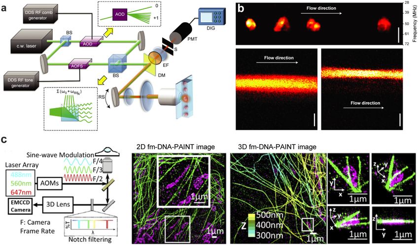
Figure 3. Examples of random-access scanning microscopes. (a) Change in collimation (focal length FAOL ) and angular deflection
(θ (x, t)) by counter-propagating chirped acoustic waves in a pair of AODs. (b) 3D-AOD scanner or acousto-optic lens (AOL)
containing polarization control (λ/2 plate) and four orthogonally arranged AODs with relay telescopes. (c) Fast 3D monitoring
of dendritic and spine (orange circle) calcium dynamics. Scale bar 2 µm, acquisition rate 3 kHz. The axial distances, relative to the
objective focus, of the selected sites are color-coded. (a)-(c) Reprinted by permission from Springer Nature Customer Service
Centre GmbH: Springer Nature, Nature Neuroscience [78] 2008. (d) 3D-RAM for in vivo application. (i) Sketch of in vivo
experiment, namely, staining by bolus loading in V1 region of a mouse. (ii) Maximal intensity projections of an entire Z-stack
(400 × 400 × 500 µm3 ) with 532 cell locations (spheres) color-coded in relation to their depth. (iii) Examples of spontaneous
neuronal network activity (calcium transients) of few cells shown in (ii). (d) Reprinted by permission from Springer Nature
Customer Service Centre GmbH: Springer Nature, Nature Methods [83] 2012. (e) 3D-RAM for in vivo imaging on behaving
animals. (i) Visual stimulation of neuronal activity in unrestrained mouse. (ii) 3D image (140 × 70 × 80 µm3 ) of a dendritic
segment of a target neuron. A 3D ribbon (blue dashed lines) for fast 3D DRIFT scanning. (iii) Calculated calcium transients after
stimulation. (e) Reproduced from [84]. CC BY 4.0.
transients at rates as high as 10 kHz in vitro [78], as well as in vivo with synthetic [85] and long-wavelength
genetically encoded indicators [86]. Note that, to maximize the scanned volume, wide-band AODs capable of
wider deflections are required [87]. With such AODs, volumes as large as 700 × 700 × 1400 µm3 were
scanned at sub-millisecond speed and sub-cellular spatial resolution, enabling recording the calcium activity
of more than 500 neurons [83].
An important aspect when applying 3D-RAM in awake behaving animals are motion artifacts, induced
by heartbeat, respiration, as well as any muscle contraction [84, 88]. As this can change the location of tissue
details relative to the pre-selected scanning sites, dynamic correction is necessary for long-term experiments.
Such an effect can be corrected by a nonlinear (parabolic) chirp of the acoustic waves. Thus, pre-selected
scanning points can be converted into small 3D lines, surfaces, and volumes (ribbons) that can used to
compensate for possible focal shifts. As shown in figure 3(e), this strategy enabled measurements of neuronal
activity on behaving animals, down to the spiny dendritic segments, over an axial range of 650 µm.
3.3. Frequency-division multiplexing microscopy
Besides fast z-scanning and hopping from one region to another within a sample, AO devices can be used to
boost the 2D imaging speed. The straightforward application is to use AODs for rapid scanning in confocal
or two-photon microscopes [89]. In these cases, though, even faster approaches exist such as the widely
commercialized resonant galvo-scanners [90]. More recent applications have combined parallelization
methods with AO devices. Examples include the use of beam-splitting gratings [91] and multiple
illumination paths, each resulting in a different z-focus position [92]. Among them, frequency-division
multiplexing (FDM) microscopy offers arguably the fastest 2D imaging speed.
The essence of FDM is to simultaneously illuminate multiple points of a sample, each at a specific
temporal frequency. Thus, there is a univocal relationship between modulated frequency and position. In
other words, the position is encoded in the frequency. The overall signal from the sample is recorded with a
single photodetector. By decoding the signal in the frequency domain, e.g. using a Fourier transform, the
intensity of each frequency component can be retrieved, and consequently, an image can be reconstructed.
10J. Phys. Photonics 3 (2021) 012004 M Duocastella et al
Figure 4. Frequency-division multiplexing microscopy. (a) Schematic of an FDM confocal microscope. Exploiting a frequency
comb, the AOD produces a single diffracted first-order beam for each driving frequency (top inset) and interference-based beat
frequencies (bottom inset). BS, beam splitter; AOD, acousto-optic deflector; AOFS, acousto-optic frequency shifter; DM, dichroic
mirror; EF, fluorescence emission filter; OL, objective lens; PMT, photomultiplier; DIG, digital oscilloscope; RS, resonant scanning
mirror. (b) Top: images acquired with setup (a) corresponding to breast carcinoma cells flowing at 1 m s−1 . Bottom: comparison
with an EMCCD camera. The long exposure time and frame transfer (10 ms) of the EMCCD caused blurring. (b) Reprinted by
permission from Springer Nature Customer Service Centre GmbH: Springer Nature, Nature Photonics [93] 2013. (c) Left: scheme
of an FDM system with wide-field detection used for super-resolution imaging. Each laser is sinewave-modulated at F/2, F/3, and
F/4, with F being the camera frame rate. Center: 2D images of mitochondria (magenta) and microtubules (green). Right: 3D
image of microtubules color-coded for Z-position (from 300 nm, blue, to 500 nm, yellow). Reproduced from [100]. CC BY 4.0.
As in FDM used in telecommunications, this strategy increases the rate of data recording by dividing the
available detection band into multiple non-overlapping frequency channels, each carrying a separate signal.
Compared to sequential scanning methods, and provided a frequency bandwidth large enough, FDM can
increase the imaging speed by a factor equal to the number of illuminating points. Note, though, that this
imaging modality typically needs relative long acquisition times to resolve the individual frequency
components, depending on their period duration. Therefore, it is essential to modulate the excitation light at
high frequencies. The ability of AO devices to frequency-shift the diffracted light renders them optimal tools
for modulating light in the MHz-range. At such high-modulation frequencies, FDM enables imaging at rates
at thousands of frames per second.
Given the intrinsic high speed of single-point photodetectors, FDM is most commonly implemented in
laser-scanning systems [93–96]. As shown in figure 4(a), the typical elements consist of a single AOD and an
AOFS. By driving the AOD with different radiofrequencies, a 1D comb of beamlets is obtained, each with a
given deflection angle and frequency shift (tone). By interfering such multi-tone comb with the beam
providing from the output of the AOFS (reference beam), the intensity of each beamlet can be modulated at
MHz-range. Indeed, the interfering process results in frequency beats, whose frequency is the difference
between the tone of each beamlet and that of the reference beam. When illuminating a fluorescent or
scattering sample [97, 98] with such a comb of modulated beamlets, the univocal relationship between
position and modulation frequency is established. Combining two AODs can result in 2D-combs of
beamlets, enabling direct reconstruction of 2D images [99]. In most common implementations, though, the
sample is illuminated with only 1D-line, thus requiring additional scanning for 2D or 3D images. While
traditional galvo-scanners can be used [95], this extra degree of freedom is intrinsic to imaging flow
cytometry systems. In this case, the temporal displacement of objects flowing in microfluidic channels acts as
an additional scanned axis (see figure 4(b)). By using the 1D-comb of modulating beamlets to illuminate the
direction perpendicular to the flow, 2D fluorescence confocal images have been acquired at kHz rates [93],
with the main speed limited being imposed by the fluorescence lifetime of the fluorophore [94]. By
combining flow imaging with z-focusing methods, z-stacks can be acquired. Using this strategy, 3D images of
microalgal cells have been acquired at 100 volumes per second without motion blurring [94].
FDM can also be implemented in wide-field imaging systems, such as light-sheet [101] and
super-resolution microscopes based on single molecule localization approaches [100]. These systems cannot
11J. Phys. Photonics 3 (2021) 012004 M Duocastella et al
perform as fast as the previously described ones due to the limited frame rate of cameras. Still, they can
outperform traditional implementations. For instance, by modulating different colors, each with a particular
frequency, simultaneous super-resolution multi-color imaging using a monochromatic camera becomes
possible (figures 4(c)–(e)). The gain in speed is proportional of the number of colors detected, while the
localization precision of the native microscope is maintained.
Advantages of FDM, besides speed, are the possibility to improve the SNR of the reconstructed image. By
applying lock-in detection algorithms, each unique beat frequency can be retrieved while filtering out any
external source of noise. However, the shot-noise of each point (plane) is shared by all the multiplexed points
(planes). This can be specially detrimental when imaging bright objects close to dim ones, however
synthetically extending the acquisition time by phase-matching techniques can mitigate this effect [95].
Another advantage of the technique is the compatibility with highly scattering samples. Specifically, FDM
combined with wavefront shaping has been successfully used to enhanced the laser focused intensity by a
factor of 125 inside a 3 mm-thick chicken breast [99]. Special consideration must be given to the modulation
bandwidth of AO devices and crosstalk between frequency beats. Typically, a large tone spacing is desirable to
facilitate image reconstruction and avoid crosstalk. Unfortunately, the limited modulation bandwidth of AO
devices determines the number of points that can be simultaneously illuminated. Strategies to increase such
bandwidth include quadrature amplitude modulation [94]. Also, by properly selecting the phase of each tone
or using machine-learning algorithms [102], crosstalk effects can be reduced. Today, state-of-the-art FDM
systems feature about 100 comb lines with tone spacing of 1 MHz and a bandwidth of 200 MHz.
4. Summary and future outlook
The inertia-free nature and tunability of AO devices enables unprecedented light control in optical
microscopy, opening the door to advancing research in important areas such as optical inspection, metrology
or biology. Here we provided some key examples to illustrate how the unique properties of AO devices enable
novel microscope designs capable of volumetric imaging at high spatiotemporal resolution. Thus, the fast
z-scanning of a TAG lens allows rapid collection of a z-stack or dynamic extension of the depth-of-field of a
microscope, significantly reducing 3D acquisition time. Similarly, selection and superimposition of the
acoustic frequencies applied to an AOD has been recognized as the primary enabler of advanced scanning
strategies in confocal and two-photon microscopes that further boost imaging rates by scanning pre-selected
points of a volume or encoding spatial information in the frequency domain. As a result of these new
developments, it is possible today to study fast dynamic processes such as neuronal communication at the
cellular level and sub-millisecond resolution. The future of AO for optical microscopy looks even brighter. As
progress will be made in the speed and sensitivity of light detectors [103, 104], volumetric imaging will be
performed at even higher spatial resolution and speed. Combined with the help of artificial intelligence [105]
or fast algorithms [106, 107], AO devices will increasingly become a fundamental tool of advanced imaging
systems.
In order to keep this review compact, certain topics were not addressed here, including the use of AO
devices for improving the spatial resolution of microscopes beyond the diffraction limit. In this regard, AOD
systems have already been used in super-resolution systems based on single molecule localization [100],
stimulated emission depletion microscopy [108], or SIM [27]. As new AO devices are being developed for
dynamic light pattern generation, such as the recently implemented AOF [19], faster super-resolution
methods with minimal photobleaching will become possible. Based on these results, we envision future AO
systems that will continue to push the limits of optical microscopy, offering new opportunities to study
biological processes at high spatiotemporal resolution and over a large volume, thus providing a clearer
picture of living organisms and their functions from the molecular to the macroscopic scale.
Acknowledgments
We acknowledge financial support from Compagnia di San Paolo, ROL 34704. MD is a Serra Hunter Fellow.
ORCID iD
Martí Duocastella https://orcid.org/0000-0003-4687-8233
References
[1] Xavier G B and Lima G 2020 Quantum information processing with space-division multiplexing optical fibres Commun. Phys.
3 1–11
[2] Seletskiy D V, Epstein R and Sheik-Bahae M 2016 Laser cooling in solids: advances and prospects Rep. Prog. Phys. 79 096401
12J. Phys. Photonics 3 (2021) 012004 M Duocastella et al
[3] Conchello J and Lichtman J W 2005 Optical sectioning microscopy Nat. Methods 2 920–31
[4] Helmchen F and Denk W 2005 Deep tissue two-photon microscopy Nat. Methods 2 932–40
[5] Mertz J 2011 Optical sectioning microscopy with planar or structured illumination Nat. Methods 8 811–9
[6] Chang B J, Kittisopikul M, Dean K M, Roudot P, Welf E S and Fiolka R 2019 Universal light-sheet generation with field synthesis
Nat. Methods 16 235–8
[7] Chen B C et al 2014 Lattice light-sheet microscopy: imaging molecules to embryos at high spatiotemporal resolution Science
346 1257998
[8] Gissibl T, Thiele S, Herkommer A and Giessen H 2016 Two-photon direct laser writing of ultracompact multi-lens objectives Nat.
Photon. 10 554–60
[9] Surdo S, Carzino R, Diaspro A and Duocastella M 2018 Single-shot laser additive manufacturing of high fill-factor microlens
arrays Adv. Opt. Mater. 6 1701190
[10] Nikolenko V, Watson B O, Araya R, Woodruff A, Peterka D S and Yuste R 2008 SLM microscopy: scanless two-photon imaging
and photostimulation with spatial light modulators Front. Neural Circuits 2 5
[11] Booth M J 2014 Adaptive optical microscopy: the ongoing quest for a perfect image Light Sci. Appl. 3 e165–e165
[12] Wu Y, Wu X, Lu R, Zhang J, Toro L and Stefani E 2015 Resonant scanning with large field of view reduces photobleaching and
enhances fluorescence yield in STED microscopy Sci. Rep. 5 14766
[13] Kang S K, Duocastella M and Arnold C B 2020 : Variable optical elements for fast focus control Nat. Photon. 14 533-42
[14] Schneider J, Zahn J, Maglione M, Sigrist S J, Marquard J, Chojnacki J, Kräusslich H-G, Sahl S J, Engelhardt J and Hell S W 2015
Ultrafast, temporally stochastic STED nanoscopy of millisecond dynamics Nat. Methods 12 827–30
[15] Hou S, Lang X and Welsher K 2017 Robust real-time 3D single-particle tracking using a dynamically moving laser spot Opt. Lett.
42 2390
[16] Korpel A 1997 Acousto-Optics (New York: Marcel Dekker, Inc)
[17] Klein W R and Cook B D 1967 Unified approach to ultrasonic light diffraction IEEE Trans. Sonics Ultrason. 14 123–34
[18] Raman C V and Nagendra Nath N S 1935 The diffraction of light by high frequency sound waves: part I Proc. Indian Acad. Sci. A
2 406–12
[19] Surdo S and Duocastella M 2019 Fast acoustic light sculpting for on-demand maskless lithography Adv. Sci. 6 1900304
[20] Dixon R W 1967 Acoustic diffraction of light in anisotropic media IEEE J. Quantum Electron. 3 85–93
[21] Goutzoulis A P and Pape D R Design and Fabrication of Acousto-Optic Devices (New York: Marcel Dekker, Inc) 1994
[22] Lechleiter J D, Lin D T and Sieneart U 2002 Multi-photon laser scanning microscopy using an acoustic optical deflector Biophys.
J. 83 2292–9
[23] Harris S E and Wallace R W 1969 Acousto-optic tunable filter J. Opt. Soc. Am. 59 744–7
[24] Suhre D R 1992 Spatial resolution of imaging noncollinear acousto-optic tunable filters Opt. Eng. 31 2118
[25] Wachman E S, Niu W H and Farkas D L 1997 AOTF microscope for imaging with increased speed and spectral versatility Biophys.
J. 73 1215–22
[26] Zunino A, Surdo S and Duocastella M 2019 Dynamic multifocus laser writing with acousto-optofluidics Adv. Mater. Technol.
4 1–7
[27] Gliko O, Brownell W E and Saggau P 2009 Fast two-dimensional standing-wave total-internal-reflection fluorescence microscopy
using acousto-optic deflectors Opt. Lett. 34 836–8
[28] Olivier N, Mermillod-Blondin A, Arnold C B and Beaurepaire E 2009 Two-photon microscopy with simultaneous standard and
extended depth-of-field using a tunable acoustic gradient-index lens Opt. Lett. 34 1684–6
[29] Mermillod-Blondin A, McLeod E and Arnold C B 2008 High-speed varifocal imaging with a tunable acoustic gradient index of
refraction lens Opt. Lett. 33 2146–8
[30] Duocastella M, Sun B and Arnold C B 2012 Simultaneous imaging of multiple focal planes for three-dimensional microscopy
using ultra-high-speed adaptive optics J. Biomed. Opt. 17 050505
[31] Piazza S, Bianchini P, Sheppard C, Diaspro A and Duocastella M 2018 Enhanced volumetric imaging in 2-photon microscopy via
acoustic lens beam shaping J. Biophoton. 11 e201700050
[32] McLeod E, Hopkins A B and Arnold C B 2006 Multiscale Bessel beams generated by a tunable acoustic gradient index of
refraction lens Opt. Lett. 31 3155–7
[33] Dean K M and Fiolka R 2014 Uniform and scalable light-sheets generated by extended focusing Opt. Express 22 26141
[34] Duocastella M, Arnold C B and Puchalla J 2017 Selectable light-sheet uniformity using tuned axial scanning Microsc. Res. Tech.
80 250–9
[35] Duocastella M and Arnold C B 2013 Enhanced depth-of-field laser processing using an ultra-high-speed axial scanner Appl. Phys.
Lett. 102 061113
[36] Zong W et al 2015 Large-field high-resolution two-photon digital scanned light-sheet microscopy Cell Res. 25 254–7
[37] Power R M and Huisken J 2018 Adaptable, illumination patterning light sheet microscopy Sci. Rep. 8 1–11
[38] Kang S, Dotsenko E, Amrhein D, Theriault C and Arnold C B 2018 Ultra-high-speed variable focus optics for novel applications
in advanced imaging Proc. of SPIE—The Int. Society for Optical Engineering vol 10539
[39] Grulkowski I, Szulzycki K and Wojtkowski M 2014 Microscopic OCT imaging with focus extension by ultrahigh-speed
acousto-optic tunable lens and stroboscopic illumination Opt. Express 22 31746
[40] Yang X, Jiang B, Song X, Wei J and Luo Q 2017 Fast axial-scanning photoacoustic microscopy using tunable acoustic gradient lens
Opt. Express 25 7349–57
[41] Fahrbach F O, Voigt F F, Schmid B, Helmchen F and Huisken J 2013 Rapid 3D light-sheet microscopy with a tunable lens Opt.
Express 21 21010–26
[42] Olarte O E, Andilla J, Artigas D and Loza-Alvarez P 2015 Decoupled illumination detection in light sheet microscopy for fast
volumetric imaging Optica 2 702
[43] Tomer R, Lovett-barron M, Kauvar I, Broxton M and Deisseroth K 2015 Resource SPED light sheet microscopy : fast mapping of
biological system structure and function Cell 163 1796–806
[44] Duocastella M, Sancataldo G, Saggau P, Ramoino P, Bianchini P and Diaspro A 2017 Fast inertia-free volumetric light-sheet
microscope ACS Photonics 4 1797–804
[45] Kong L, Tang J, Little J P, Yu Y, Lämmermann T, Lin C P, Germain R N and Cui M 2015 Continuous volumetric imaging via an
optical phase-locked ultrasound lens Nat. Methods 12 759–62
[46] Gavryusev V et al 2019 Dual-beam confocal light-sheet microscopy via flexible acousto-optic deflector J. Biomed. Opt. 24 106504
13You can also read