Night Vision Technologies Handbook - System Assessment and Validation for Emergency Responders (SAVER) - Homeland Security
←
→
Page content transcription
If your browser does not render page correctly, please read the page content below
System Assessment and Validation for Emergency Responders (SAVER)

Night Vision Technologies Handbook
October 2013

           Prepared by Space and Naval Warfare Systems Center Atlantic

                     Approved for public release; distribution is unlimited.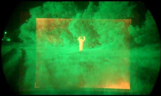
The Night Vision Technologies Handbook was funded under Interagency Agreement
No. HSHQPM-12-X-00031 from the U.S. Department of Homeland Security, Science and
Technology Directorate.
The views and opinions of authors expressed herein do not necessarily reflect those of the
U.S. Government.
Reference herein to any specific commercial products, processes, or services by trade
name, trademark, manufacturer, or otherwise does not necessarily constitute or imply its
endorsement, recommendation, or favoring by the U.S. Government.
The information and statements contained herein shall not be used for the purposes of
advertising, nor to imply the endorsement or recommendation of the U.S. Government.
With respect to documentation contained herein, neither the U.S. Government nor any of
its employees make any warranty, express or implied, including but not limited to the
warranties of merchantability and fitness for a particular purpose. Further, neither the
U.S. Government nor any of its employees assume any legal liability or responsibility for
the accuracy, completeness, or usefulness of any information, apparatus, product or process
disclosed; nor do they represent that its use would not infringe privately owned rights.
Photographs and illustrations included herein were provided by Space and Naval Warfare
Systems Center Atlantic under the Interagency Agreement, unless otherwise noted.
Approved for public release; distribution is unlimited.
FOREWORD
The U.S. Department of Homeland Security (DHS) established the System Assessment and
Validation for Emergency Responders (SAVER) Program to assist emergency responders
making procurement decisions. Located within the Science and Technology Directorate (S&T)
of DHS, the SAVER Program conducts objective assessments and validations on commercial
equipment and systems and provides those results along with other relevant equipment
information to the emergency responder community in an operationally useful form. SAVER
provides information on equipment that falls within the categories listed in the DHS Authorized
Equipment List (AEL). The SAVER Program mission includes:
Conducting impartial, practitioner-relevant, operationally oriented assessments and
validations of emergency response equipment; and
Providing information, in the form of knowledge products, that enables
decision-makers and responders to better select, procure, use, and maintain emergency
responder equipment.
Information provided by the SAVER Program will be shared nationally with the responder
community, providing a life- and cost-saving asset to DHS, as well as to Federal, state, and local
responders.
The SAVER Program is supported by a network of Technical Agents who perform assessment
and validation activities. Further, SAVER focuses primarily on two main questions for the
emergency responder community: “What equipment is available?” and “How does it perform?”
As a SAVER Program Technical Agent, the Space and Naval Warfare Systems Center
(SPAWARSYSCEN) Atlantic has been tasked to provide expertise and analysis on key subject
areas, including communications, sensors, security, weapon detection, and surveillance, among
others. In support of this tasking, SPAWARSYSCEN Atlantic conducted a review of night
vision technologies. Night vision technologies fall under AEL reference numbers
04MD-01-LAMP: Equipment, Light Amplification and 03OE-02-TILA: Optics, Thermal
Imaging and/or Light Amplification.
Visit the SAVER section of the Response Knowledge Base (RKB) website at
http://www.rkb.us/saver for more information on the SAVER Program or to view additional
reports on CCTV or other technologies.
i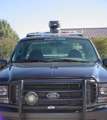
POINTS OF CONTACT
SAVER Program
U.S. Department of Homeland Security
Science and Technology Directorate
OTE Stop 0215
245 Murray Lane
Washington, DC 20528-0215
E-mail: saver@hq.dhs.gov
Website: http://www.rkb.us/saver

Space and Naval Warfare Systems Center Atlantic
Advanced Technology and Assessments Branch
P.O. Box 190022
North Charleston, SC 29419-9022
E-mail: ssc_lant_saver_program.fcm@navy.mil

                                              ii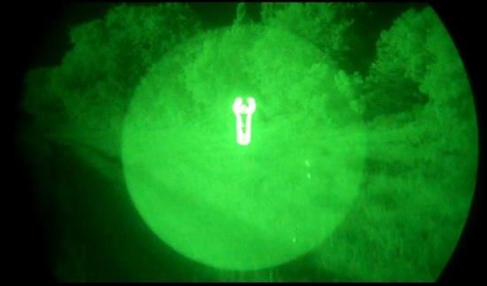
TABLE OF CONTENTS
Foreword..................................................................................................................................... i
Points of Contact ........................................................................................................................ ii
Preface ...................................................................................................................................... vi
1. Introduction ...........................................................................................................................1
    1.1       The Visible Light Spectrum .........................................................................................1
    1.2       History of Night Vision Technology ............................................................................2
2. Night Vision Technology Reviews ........................................................................................3
    2.1       Image Intensification ...................................................................................................3
    2.2       Thermography .............................................................................................................7
    2.3       Near Infrared Illumination ...........................................................................................9
    2.4       Integrated Night Vision.............................................................................................. 10
    2.5       Emerging Technologies ............................................................................................. 11
3. Applications ........................................................................................................................ 11
    3.1       Law Enforcement Applications .................................................................................. 12
    3.2       Fire and Rescue Applications ..................................................................................... 12
    3.3       Natural Resource Agency Applications ...................................................................... 13
    3.4       Security Applications ................................................................................................. 14
    3.5       Engineering Applications ........................................................................................... 14
    3.6       Medical Applications ................................................................................................. 15
4. Acquisition Considerations .................................................................................................. 15
    4.1       Common Night Vision Device Considerations ........................................................... 15
    4.2       Image Intensifier Considerations ................................................................................ 17
    4.3       Thermal Imager Considerations ................................................................................. 19
    4.4       Integrated Night Vision Considerations...................................................................... 20
5. Accessories ......................................................................................................................... 20
    5.1       Eyeguards .................................................................................................................. 20
    5.2       Lens Adapters ............................................................................................................ 21
    5.3       Camera Adapters ....................................................................................................... 21
    5.4       NIR Illuminators........................................................................................................ 21
    5.5       Sacrificial Window .................................................................................................... 21
    5.6       Magnetic Compasses ................................................................................................. 22

                                                                       iii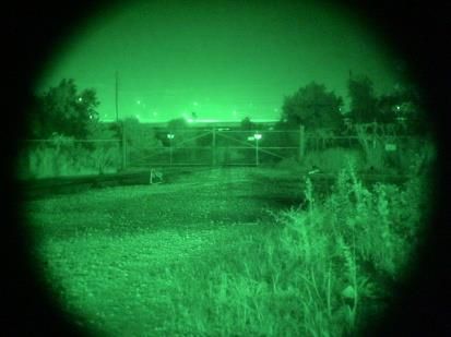
5.7       Waterproof and Water-Resistant Night Vision Devices .............................................. 22
    5.8       Laser Range Finder .................................................................................................... 22
    5.9       Headgear ................................................................................................................... 22
6. Vendor Matrix ..................................................................................................................... 23
Appendix A.           Definitions .................................................................................................... A-1

LIST OF TABLES
Table 6-1. Vendors and Types of Products ............................................................................... 23
Table 6-2. Additional Vendors ................................................................................................. 24

LIST OF FIGURES
Figure 1-1. I2 Display .................................................................................................................1
Figure 1-2. Visible Light and Infrared in the Electromagnetic Spectrum .....................................1
Figure 1-3. Night Glasses ...........................................................................................................2
Figure 1-4. Gen 1 Starlight Scope...............................................................................................2
Figure 1-5. Firefighter Using a Thermal Imaging Camera...........................................................3
Figure 2-1. Multiple Technologies Scene Displays .....................................................................3
Figure 2-2. Gen 2 and Gen 3 Photomultiplier Tube Operating Principle .....................................4
Figure 2-3. I2 Display .................................................................................................................4
Figure 2-4. Gen 0 NVD ..............................................................................................................5
Figure 2-5. Gen 1 NVD ..............................................................................................................5
Figure 2-6. Gen 2 NVD ..............................................................................................................6
Figure 2-7. Microchannel Plate ..................................................................................................6
Figure 2-8. White Phosphor Image .............................................................................................7
Figure 2-9. Thermal Image of Vehicles ......................................................................................8
Figure 2-10. Cooled Thermal Imaging Camera ...........................................................................9
Figure 2-11. INVS Image ......................................................................................................... 10
Figure 2-12. INVS Using Thermal Outline ............................................................................... 11
Figure 3-1. I2 Image Display .................................................................................................... 12
Figure 3-3. Thermal Image Display of Fire Behind a Wall ....................................................... 12
Figure 3-2. Thermal Image of Residual Heat From A Hand On Wooden Fence ........................ 12

                                                                     iv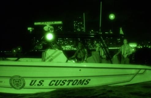
Figure 3-4. Thermal Imaging Camera Display .......................................................................... 13
Figure 3-5. Thermal Image Display of Overhaul ...................................................................... 13
Figure 3-6. I2 Image Display .................................................................................................... 13
Figure 3-7. Security Truck using Mounted Thermal Imaging Camera ....................................... 14
Figure 3-8. Thermal Image Display of an Engine ..................................................................... 14
Figure 3-9. Thermal Medical Display of the Human Body........................................................ 15
Figure 4-1. Monocular NVD .................................................................................................... 17
Figure 4-2. Binocular NVD ...................................................................................................... 17
Figure 4-3. NVD Rifle Scope ................................................................................................... 18
Figure 4-4. NVD Goggles ........................................................................................................ 18
Figure 4-5. 1951 USAF Resolution Target ............................................................................... 18
Figure 4-6. Haloing Example ................................................................................................... 19
Figure 5-1. Eyeguard ................................................................................................................ 20
Figure 5-2. Doubler Lens Adapter ............................................................................................ 21
Figure 5-3. Assault Rifle With Dual Beam Infrared Illuminator ................................................ 21
Figure 5-4. Sacrificial Window ................................................................................................ 21
Figure 5-5. Headgear ................................................................................................................ 22

                                                                   v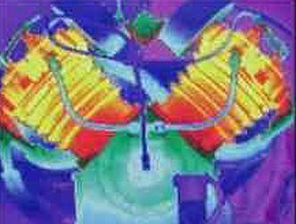
Night Vision Technologies Handbook
PREFACE
This Night Vision Technologies Handbook provides emergency responders, law enforcement,
and security professionals with a reference on night vision technologies, capabilities, and
limitations. This handbook provides introductory-level information on the technologies and
components for night vision devices (NVDs), as well as an overview of their applications.
Efforts to acquire or use an NVD should be undertaken only in consultation with organizations
or individuals experienced in this technology.
This handbook examines NVDs and technologies for applications that include law enforcement,
natural resource management, fire and rescue, emergency management, engineering, medical,
and security services. The devices described include the following:
Image intensifiers (I2);
Thermal imaging cameras;
Integrated night vision systems (INVSs); and
Near infrared (NIR) illuminators.
This handbook also discusses NVD operating principles and products, and the performance
factors and other attributes to consider when selecting an NVD. In addition, this handbook
provides a history of NVDs, a list of accessories for use with NVDs, and a brief discussion of
emerging night vision technologies. A vendor/product matrix is provided to identify the
products found in the market research. The matrix is not intended to be an all-inclusive list of
equipment suppliers or products, and NVDs under development or restricted to military use are
not included in the matrix. Definitions of terminology commonly used and/or associated with
night vision technologies are provided at the end of the handbook.
vi
Night Vision Technologies Handbook
1. INTRODUCTION
A night vision device (NVD) is an electro-optical
device that enhances vision in environmental
conditions with little or no light. Since World
War II, NVDs have been used by military
organizations as a force multiplier, greatly
extending military operational capabilities in
nighttime or low-light scenarios. NVD
technology is used by many non-military
agencies, such as law enforcement, fire, and
search and rescue. NVDs include Image
Figure 1-1. I2 Display
Intensifier (I2) devices, thermal imaging cameras,
integrated night vision systems (INVSs), and Courtesy of ITT
near infrared (NIR) illuminator technology. An
example of an I2 display is shown in Figure 1-1. NVDs can enhance almost any emergency
response agency’s operational capability by enabling the user to perform one or more of the
following functions:
Detection–detect an object in limited light;
Recognition–recognize the object; and
Identification–identify distinguishing features.
A brief review of the electromagnetic spectrum and a history of NVDs are provided to assist the
reader in understanding how NVDs can enhance emergency responders’ capabilities.
1.1 The Visible Light Spectrum
Visible light represents a narrow band of the greater electromagnetic spectrum, as shown in
Figure 1-2. The visible spectrum contains all colors from violet to red. Each of the colors in the
visible spectrum has its own characteristic wavelength. The wavelengths of visible light
correspond to a range between approximately 400 (violet) and 700 (red) nanometers (nm). It is
the reflection of light within the visible wavelength that results in objects appearing in color to
the human eye. For example, objects appear green because all of the other observable color
wavelengths are absorbed by the objects surface except for green, which is reflected.
Figure 1-2. Visible Light and Infrared in the Electromagnetic Spectrum
1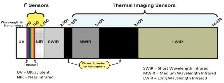
Night Vision Technologies Handbook

NVDs are sensitive to sections of the electromagnetic spectrum, commonly called bands or
frequency bands, which are outside the range of human vision. Section 2 discusses how each
NVD technology utilizes a specific portion of the electromagnetic spectrum as defined by the
NVD industry and depicted in Figure 1-2.

1.2     History of Night Vision Technology
Night glasses were one of the first NVDs developed. They were
simple optical devices, similar to binoculars or a telescope, with
large diameter objective lenses. Night glasses, such as those seen
in Figure 1-3, had 55 millimeter (mm) or larger objective lenses
and at least 7x magnification. They were heavy and often
dangerous to use because the pupil reflex of the eye is not fast
enough to prevent damage from sudden exposure to a large
                                                                         Figure 1-3. Night Glasses
amount of light.

1.2.1 Development of image Intensification
Other products developed during World War II include the cascade image tube and the infrared
illuminator. Initial development efforts of I2 NVDs depended on active infrared illumination of a
target in order to operate. In combat or surveillance, active illumination devices have limited
usefulness, because they can reveal the source of light to an adversary using a device capable of
seeing infrared. These technologies are explained in more detail in Section 2.1.
The I2 technology as it existed then is known as Generation 0 (Gen 0) I 2. The U.S. military used
this type of device during the Korean War.
The first passive military I2 NVDs were used during
the Vietnam War. These Generation 1 (Gen 1) I2
NVDs are known as starlight scopes as they used
ambient light from the moon and stars to enhance
available lighting. These devices were bulky and
cumbersome, but since they did not use any additional
illumination (i.e., infrared), the user’s location was       Figure 1-4. Gen 1 Starlight Scope
not revealed. An example of a Gen 1 starlight scope
                                                            Photo by U.S. Army Center of Military History
is shown in Figure 1-4.
Produced in the 1980s, Generation 2 (Gen 2) I 2 NVDs provided substantial improvements in
performance and packaging. Performance was improved by the addition of a microchannel plate
(MCP) to the image-intensifier tube. The MCP resulted in images that were less distorted and
brighter than earlier-generation NVDs. The reduction in size and weight permitted the device to
be attached to a helmet or other headgear. Gen 2 devices are the most commonly available I2
NVDs due to their record of performance and low relative cost.
Generation 3 (Gen 3) I2 NVDs were developed in the late 1980s, and were used extensively
during the Gulf War in 1991. This generation NVD provided more light amplification and a
longer service life than the prior generation NVDs. Gen 3 devices that amplify low ambient light
levels by 30,000 to 50,000 times are becoming more commonplace outside military applications.

                                                 2
Night Vision Technologies Handbook
1.2.2 Development of Thermal Imaging Cameras
Thermal imaging cameras allow users to see the thermal infrared radiation emitted by objects.
The infrared energy radiated from objects depends on the objects’ temperatures and the
difference in temperatures can be seen as different colors or shades of gray. As these cameras do
not use light, they are effective even in total darkness.
The development of the thermal imaging camera (also
known as a thermal imager) began in the late 1960s as an
aid to air navigation. Customizing thermal imaging
cameras for use in other military applications began in
the 1970s. The first commercial thermal imagers became
available in the 1980s. In the 1990s, thermal imaging
sensor technology enhancements included greater
sensitivity and higher resolution. Since then, thermal Figure 1-5. Firefighter Using a
imaging cameras have found broad acceptance in law Thermal Imaging Camera
enforcement, fire and rescue, engineering, medical
services, and the security industry (see Figure 1-5). Photo Courtesy of National Fire Academy
2. NIGHT VISION TECHNOLOGY REVIEWS
There are advantages and disadvantages associated with each type of NVD technology. As
briefly discussed in Section 1, all NVDs can enable a user to perform three basic
functions—detection, recognition, and identification—to some degree, in low or no light
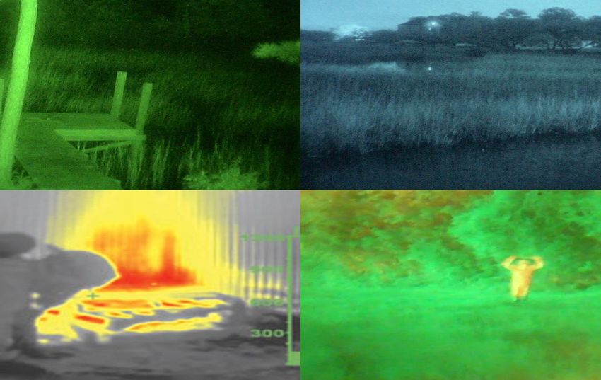
conditions. The same scene in daylight and using NVD technologies can be seen in Figure 2-1.
Digital Day Image Thermal Night Image I2 Night Image
Figure 2-1. Multiple Technologies Scene Displays
2.1 Image Intensification
2
I devices use light-amplifying technology that requires minimal light to operate. These devices
are produced as monoculars, binoculars, goggles, and riflescopes. I2 technology is generally
categorized within four generations as established by the U.S. Army’s Night Vision and
Electronic Sensors Directorate (NVESD) (http://www.nvl.army.mil). These generations are
based on the components and level of sophistication of the image intensification technology and
include: Gen 0, Gen 1, Gen 2, and Gen 3. Some manufacturers have expanded the designations
to include Generation 2 plus (Gen 2+), Generation 3 plus (Gen 3+) and Generation 4 (Gen 4),
though these are not included in the NVESD categorizations.
3Night Vision Technologies Handbook
2.1.1 Operating Principle
I2 devices use components known as photomultiplier tubes to enable visibility in very low-light
scenarios. The overall operating principle for Gen 2 and 3 photomultiplier tubes is illustrated in
Figure 2-2. The photomultiplier tubes use a lens to collect available light, including light from
the infrared portion of the spectrum. Once past the lens, the light strikes the photocathode which
causes the release of an electron.
Figure 2-2. Gen 2 and Gen 3 Photomultiplier Tube Operating Principle
The electrons travel through the tube, accelerating towards another
plate and causing a cascade effect that increases the number of
electrons. These electrons strike a screen coated with a
phosphorescent compound that will glow as shown in Figure 2-3.
When using an I2 NVD, the operator views the scene through an
ocular lens that focuses the image. A separation between the ocular
lens and the eye, known as eye relief distance, is necessary.
Many types of phosphor screens are available on I2 devices, with the Figure 2-3. I2 Display
most common being designated P22 (green), P43 (yellow-green), and
P45 (white). The P22 screen is the most commonly used, and is the popular choice for military
and law enforcement due to the wider visible spectrum. The P43 screen has a narrower visible
spectrum and has become popular among aviators for its fast decay time (i.e., the time it takes for
the image to fade on the screen). The P45 screen provides similar decay times to P43, with
excellent recognition capability. The image presented to the user of a P45 screen is black and
white, which results in less eye fatigue, faster recognition (especially in sandy/rocky terrain), and
a slightly better discrimination of shades of intensity than the traditional green.
4Night Vision Technologies Handbook
2.1.2 Image Intensifier Technologies
As discussed in Section 1.1, night glasses were the earliest passive NVD and employed a large
objective lens that captured available light (photons) and condensed that light into a much
smaller area.
2.1.2.1 Generation 0 Image Intensifiers
I2 Gen 0 technology used active NIR illumination that
cannot be seen by the human eye. In a Gen 0 system,
invisible light from an infrared illuminator reflected off
objects in the scene and back to the objective lens of
the NVD, as shown in Figure 2-4. The sensor element
employed a control grid between the photocathode and
the phosphor screen to accelerate the flow of electrons
toward the phosphor screen. This acceleration process
caused premature deterioration of the tube, reducing its
useable service life and somewhat distorting the image.
Gen 0 NVDs are no longer available on the commercial
or military market. Figure 2-4. Gen 0 NVD
2.1.2.2 Generation 1 Image Intensifiers
I2 NVD technology shifted to passive infrared in
Gen 1 NVDs. As shown in Figure 2-5, Gen 1 NVDs use
essentially the same intensifier tube configuration as
Gen 0 devices. They also have the same image distortion
and short service life issues experienced with Gen 0 NVDs.
The major advantage of Gen 1 NVDs over Gen 0 devices is
that Gen 1 devices do not require an illumination source but
instead use available visible and infrared light.
Gen 1 NVDs have some undesirable characteristics,
including a high-pitched whine when they are initially
powered on, a slightly distorted image, and a tendency to
continue producing a green glow after being powered Figure 2-5. Gen 1 NVD
down.
2.1.2.3 Generation 2 Image Intensifiers
Image distortion and reduced service life issues in previous generations of I2 NVDs led to the
development of the microchannel plate (MCP). This small glass disc, as shown in Figure 2-6, is
typically one inch in diameter and has an electrode on both sides to attract and control the flow
of electrons. The MCP, as illustrated in Figure 2-7, greatly increases the number of electrons
that reach the phosphor screen, enabling effective observation with less light than earlier
generations.
5Night Vision Technologies Handbook
The MCP Gen 2 NVDs require much less power than their predecessors, and are effective in
very low-light conditions.
Figure 2-6. Gen 2 NVD Figure 2-7. Microchannel Plate
2.1.2.4 Generation 3 Image Intensifiers
Gen 3 NVDs are similar to Gen 2, except that the photocathode is composed of gallium arsenide.
This material is highly sensitive to NIR light and forms an image regardless of the degree of
illumination in the visible light spectrum by significantly amplifying the number of electrons in
the intensifier tube. In addition, the intensifier tube is coated with an ion barrier that
substantially increases the service life of the intensifier tube compared to Gen 2 tubes.
Reduced electron flow at the ion barrier may cause a loss of brightness and mild image distortion
in some Gen 3 NVDs. To counter this effect, some manufacturers have removed the ion barrier
in order to increase brightness and resolution. A second improvement resulted from the use of
an automatic gated power supply, which regulates the photocathode voltage as lighting
conditions change. Some manufacturers call this Gen 3+ or Gen 4 in their literature, but these
designations have not been adopted by the military. The accepted nomenclature for this
technology is “filmless and gated.” Filmless and gated devices have improved Gen 3 NVD
performance in both extremely low-light and bright-light environments. Gen 3 devices are
usually powered by AA batteries or a 3-volt CR-123 battery that provides approximately
40 hours of operation. The projected tube life of a Gen 3 device is 10,000 hours. The system
electronics of these devices also feature protective circuits to prevent damage to the intensifier
tube and guard against undesirable effects in the visual image, such as blooming and haloing.
These terms are described in Section 4.2.5.
2.1.2.5 Improvements on Generation 2 and Generation 3 Image Intensifiers
Since the introduction of Gen 2 and 3 devices, advances have been made in the technology
specifications and abilities of the devices. Manufacturers have developed products based on
Gen 2 technology, for example, but with clarity closer to Gen 3. These are sometimes marketed
as Gen 2+.
For Gen 3, many of the improvements have been driven by military purchases made every few
years. These purchases, known as Omnibus or OMNI purchases, contained gradually increasing
specifications for the technology. Some vendors will use the OMNI number, in roman numerals,
6Night Vision Technologies Handbook
to denote which of the specification sets the unit is compliant with. Other vendors classify these
products as Gen 3+, which indicates that the technology specifications are beyond the initial
Gen 3 specs, but are not compliant with any specific OMNI number. Some products are
marketed as Gen 4, which can be either an advancement on Gen 3, or based on the Gen 4
specifications that existed for a short time before being retroactively removed as a standard by
the military.
2.1.2.6 White Phosphor Night Vision
One of the advances in night vision is white phosphor
technology. This technology results in a grayscale
display, as seen in Figure 2-8. Images produced by a
white phosphor device may be more familiar to the
human eye, which naturally perceives poorly lit scenery
in shades of gray. White phosphor devices, which use
Gen 2+ technology, do not have the extreme low-light
performance capabilities of Gen 3 devices. White
phosphor is not as affected by blooming (i.e., the loss
of an image due to additional light sources), which
makes it useful for urban environments. In some
applications a single monocle intensifier can be used Figure 2-8. White Phosphor Image
with one eye, while the other eye remains open to
provide the user some color perception.
2.2 Thermography
Thermography is the general term for scanning, detecting, measuring, and displaying medium
wavelength infrared (MWIR) and long wavelength infrared (LWIR) radiation. Thermographic
technology is used by thermal imaging cameras and detects the relative difference in the
temperature of an object compared to the temperature of other objects in the same scene. The
emissivity of the materials in the scene also greatly affects the image. Emissivity is the
quantified ability of an object to release or emit heat. For example, in a thermographic image of
a wooded area, a warm-blooded animal stands out against the cooler forest. Similarly, when
viewed through a thermal imaging camera, an intruder’s body would stand out against the
background of an open area under surveillance. The thermal imaging camera forms an image
based on the differences in the temperature of objects within the scene. Thermal imagers can see
through light levels of fog or smoke but are unable to see through glass.
Training is an important consideration in the application of thermal imaging technology.
Because a thermal imager sees infrared radiation, and not reflected light, training is very
important to ensure that a user can understand a thermal image and receive the maximum benefit
from a thermal imager. Organizations should consider training for emergency responders that
includes examination of various materials to demonstrate the characteristic of infrared
emissivity. This characteristic determines how much infrared radiation is absorbed and released
by an object based on its composition.
7Night Vision Technologies Handbook
Examples of responder uses for thermal imagery include
evidence collection, searching for objects and determining if a
vehicle has been recently operated. As shown in Figure 2-9,
the wheels and headlights of the vehicle in the foreground are
cold, while the wheels and headlights of the vehicle in the
background emit a higher level of infrared radiation indicating
that the car may have been recently used.
All objects radiate some amount of infrared energy in the form
of heat. There are several configurations of thermal imaging Figure 2-9. Thermal Image
cameras differentiated by the technology of the detector and of Vehicles
the intended applications. Some of the configurations are
highlighted below:
Hand-held thermal imaging cameras are highly portable and useful in a broad range of
applications.
Fixed-mount installations are used when the camera must have a high degree of
stability. The characteristic of stability is required in order to form useful images at
long range. Fixed mount installations can include mounting the camera on a
pan-and-tilt platform for 360o coverage.
Vehicle-mount thermal imaging cameras are a compromise between the portability of
a hand-held device and the range of a fixed-mount device. This configuration can
greatly enhance detection capability. Vehicle mounts can be stationary to provide the
driver with only one field of view (FOV) or on a pan-and-tilt mount for 360o coverage.
Network capabilities allow thermal camera images to be viewed at a remote,
networked location. This is useful for applications requiring a coordinated team
effort. These capabilities permit personnel at a command post to make timely and
effective decisions by seeing the real-time display of the on-scene event.
2.2.1 Operating Principle
Thermal imaging cameras consist of four components: a lens, thermal detector focal plane array
(FPA), video processing electronics, and a display. The thermal detector FPA is the primary
component of any thermal imaging camera. In the FPA, thermal energy emissions from the
infrared portions of the spectrum are detected and the device emits electrons in order to create an
image of temperature differences of less than 0.1 of a degree Fahrenheit (F).
2.2.2 Thermal Imaging Camera Technologies
A fundamental difference exists between thermal imagers and other NVDs. Image intensifiers
rely on NIR wavelengths between 750 and 1100 nm when generating an image. In contrast,
thermal imagers sense the difference in temperature between a target and the surrounding
environment and rely on MWIR and LWIR bands between 3,000 and 14,000 nm. Instead of the
cascade image tube or photocathode found in I2 devices, thermal imagers utilize an FPA. Each
FPA consists of a large number of sensor elements arranged in a grid and each individual
element contributes to the final image. Thermal imaging cameras can be used in daylight or at
8Night Vision Technologies Handbook
night. Early thermal imagers were cooled; uncooled devices became available with
improvements in technology.
2.2.2.1 Cooled Thermal Imaging Cameras
Cooled thermal imaging cameras require cooling equipment that
can cool the camera’s thermal detector to a temperature as low
as 200 Kelvin (-100 F). Several cooling techniques are
currently in use, including using liquefied gasses (cryogenic),
Peltier coolers, and Stirling coolers. A Peltier cooler is a
thermoelectric component that functions as a heat pump. These
coolers are lightweight, have no moving parts, and are virtually
maintenance free. However, these coolers are not used often
due to their high energy consumption. A Stirling cooler is a Figure 2-10. Cooled
cooling device that alternately compresses and releases a gas in Thermal Imaging Camera
order to control temperature. These expensive and bulky
cameras are housed in a vacuum-sealed casing with the cryogenic cooling equipment, as seen in
Figure 2-10. Typical cooled detectors operate at 77 Kelvin or below. Cooling brings the
detector in the camera to a temperature lower than the objects being observed. This enhances the
sensitivity of the detector elements in the thermal imaging camera.
Cooled thermal imaging cameras provide the best image quality and greatest range in ambient
temperature because of the sensitivity of the cooled infrared detector system but the cooling
systems have a limited lifetime. Cooled thermal imaging cameras provide high speed and
multispectral infrared imaging; however these devices typically have a limited life, are expensive
to maintain, require 3 to 4 minutes to reach operating temperature, and are noisy during
operation.
2.2.2.2 Uncooled Thermal Imaging Cameras
The detectors in uncooled thermal imaging cameras operate at ambient temperature, but at the
expense of reduced sensitivity as compared to cooled thermal imaging cameras. Compared to
cooled thermal imaging cameras, uncooled thermal imaging cameras are less expensive, smaller
in size, and quieter.
Of the two types of devices discussed, uncooled thermal imaging cameras are rapidly becoming
the most commonly used. Uncooled thermal imaging cameras provide greater reliability than
cooled thermal imaging cameras.
2.3 Near Infrared Illumination
NIR illumination technologies can be used to enhance the performance of I2 devices. NIR
illuminators provide a light source to produce enhanced images in very low-light environments.
NIR illuminators operating at 810 nm emit a slight red glow that may be seen under conditions
of total darkness and where the illuminator is directly in the line of sight. Using indirect lighting
will eliminate any observable light signature; however, direct or indirect illumination is easily
seen with an I2 device.
9Night Vision Technologies Handbook
2.3.1 Operating Principle
NIR illuminators rely on one of three illumination technologies: incandescent, light emitting
diode (LED), or laser.
2.3.1.1 Incandescent Illuminators
Industrial halogen and tungsten bulbs produce NIR illumination in addition to large quantities of
bright, visible light. Filters can be used to block the visible light components as needed, but
these devices also produce a great deal of heat. These illuminators are appropriate for
applications where visible illumination is required, such as sports venues or parking lots. In
these applications, it is likely that the spectral characteristics of an existing lighting system will
be considered when evaluating a camera. Incandescent illuminators have a relatively short
lifespan.
2.3.1.2 LED Illuminators
LED illuminators use electrical energy more efficiently and produce much less heat than
incandescent illuminators. These devices also minimize the problem of light pollution because
they emit invisible or barely visible light.
2.3.1.3 Laser Illuminators
Although the unit cost of laser illuminators is higher than LED illuminators, their use can
provide significant cost savings. Because of their high efficiency, which is 4 to 5 times greater
than LED illuminators and 20 times or more then incandescent illuminators, laser-based
illumination systems can produce more NIR illumination per unit cost than other systems.
Laser NIR illuminators emit light at a single wavelength. This light may or may not be visible
with the naked eye. Some NIR laser illuminators feature a capability known as "range-gating,"
which uses timed pulses in order to capture high quality images from a target at a specific
distance from the camera. These pulses are timed with the shutters on the camera. By using
extremely short duration pulses, the illuminator effectively ensures that the strongest reflection
will be returned from the target of interest rather than from objects in the foreground and
background.
2.4 Integrated Night Vision
Integrated night vision systems (INVSs), also called
fused night vision or enhanced night vision,
combine image output from two or more different
types of night vision sensors into one composite, or
fused, image. A fused image takes advantage of the
strengths of each type of sensor. INVSs for
emergency responder applications commonly
couple an I2 and thermal sensor as shown in Figure
2-11. The I2 sensor provides an image of the
surrounding environment under low-light Figure 2-11. INVS Image
conditions, while the thermal imaging sensor allows
10Night Vision Technologies Handbook
for the cueing, or detection, of objects and targets of interest by showing the thermal signatures
of the objects in the environment. This fused image provides the user with enhanced detection
and recognition capability in fog, rain, and smog, as well as in poorly illuminated conditions.
There are two methods for integrating the sensor images:
optical and digital. Optical integration can be
accomplished in one of two ways. The simplest method is
called dichoptic presentation, which displays two images,
one in each eye. The user’s brain then combines the two
images into one. The other type of optical integration is
called overlay presentation, which overlays one sensor
image over the other. For example, the thermal image can
be overlaid onto the I2 image, sometimes as an outline, as
seen in Figure 2-12. Optical integration requires no Figure 2-12. INVS Using
additional power beyond that required by the sensors, so Thermal Outline
the devices can be lightweight and portable.
The digital integration for INVSs uses signal processing to combine the images from each sensor
into a single image. While digital integration offers more options and better performance, the
tradeoffs are the greater size and weight of the device, as well as the power requirements.
Therefore, INVSs using digital integration are more expensive and less portable than their
optically integrated counterparts.
2.5 Emerging Technologies
Numerous technologies are in development and may be available in the near future. They
include:
Quantum dot nanotechnology, which is adaptable to thermal imagers, may enhance
the sensitivity to infrared radiation in the 8,000 to 12,000 nm range. However, the
high cost of the technology and lack of consistent quantum dots have deterred its use
at this time.
Panoramic vision technology, which allows the user to have a wider FOV. Versions
using four tubes are already in use in military aviation. Research is in process for
curved lenses to provide night vision capability for the user’s peripheral vision.
High Sensitivity CMOS technology, which provides increased pixel surface area,
allows low-light video capture. This development also reduces noise which generally
increases with pixel size.
3. APPLICATIONS
I2 devices, thermal imaging cameras, and INVSs can be applied to missions related to law
enforcement, natural resources, fire and rescue, engineering, medical, and security. Common
applications are described in the following sections.
11Night Vision Technologies Handbook
3.1 Law Enforcement Applications
NVDs are useful tools in search and rescue operations, surveillance, apprehension, forensics,
hazardous material response, tracking, and navigation.
I2 and INVSs devices can provide high quality images using
very low levels of ambient light, as seen in Figure 3-1.
These devices are also used in covert surveillance, when an
individual’s appearance and facial characteristics must be
discerned to identify the individual.
I2 NVDs reveal details that thermal imaging cameras are
unable to capture. For example, thermal imagers can show
which weapon in a group of weapons was fired recently,
whereas I2 devices can enable a user to determine the Figure 3-1. I2 Image Display
weapon type. I2 devices are also very useful in
environments where thermal imagers would have difficulty Photo Courtesy of ITT
differentiating objects.
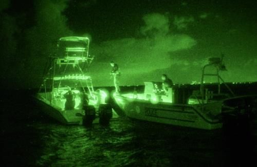
Thermal imagers are useful in law enforcement applications
because they sense differences in temperature and can be
used in any lighting conditions. Thermal imagers are highly
effective in search and rescue applications in marine
environments because water temperature tends to be
constant at the surface. A live human body presents a large
difference in temperature that stands out in sharp contrast
against the cooler surface of the water. Thermal imagers are
also useful in border surveillance, crime scene analysis, and
forensic investigation. An example of residual heat from a Figure 3-3. Thermal Image of
person who placed a hand against a wooden fence can be Residual Heat From A Hand
seen in Figure 3-3. On Wooden Fence
I2, INVSs, and thermal imaging NVDs can also help localize
a source of gunfire by adding context to a muzzle flash. Rather than just seeing the flash against
a dark background, these devices can reveal other details necessary to plan an effective response,
such as pinpointing the floor of a building where gunfire originated. They can be useful in other
tactical situations such as enhancing the speed of the operation and overall safety and assisting
officers with tactical positioning. In the context of a
methamphetamine manufacturing site, all NVD types can
assist officers searching for lurkers, lookouts, and guard dogs.
3.2 Fire and Rescue Applications
Thermal imagers are more commonly employed in fire and
rescue applications than any other NVD because the ability to
sense heat is fundamental to firefighting procedures. An
example of thermal imaging of a fire behind a wall is seen in Figure 3-2. Thermal Image
Figure 3-2. Thermal imagers can assist an incident Display of Fire Behind a Wall
commander in assessing the scene and making decisions.
Photo Courtesy of Bullard
12Night Vision Technologies Handbook
Thermal imagers are used to help locate victims, safely
navigate smoke-filled buildings, and detect the hottest parts of
a fire scene, as seen in Figure 3-4. Sometimes liquid levels in
stationary tanks and bulk liquid trailers can be detected, in
addition to gas and liquid leaks and spills. The navigation
and route planning capability of firefighters is greatly
enhanced by their ability to gather information about their
surroundings from a thermal imaging camera.
Figure 3-4. Thermal Imaging
A thermal imager can be used to confirm that a fire scene has Camera Display
been completely overhauled, which can in turn preserve
evidence on the scene for investigators. An example of this Photo Courtesy of National Fire
Academy
use can be seen in Figure 3-5. In search and rescue, grid
squares can be large, requiring responders to cover a
substantial amount of ground. Thermal imagers are also used
to identify overloaded fuse panels or loose electrical
connections.
Thermal imaging devices mounted on firefighting apparatus
and vehicles are becoming more common. Roof-mounted
devices in pan-tilt-zoom (PTZ) configurations enable vehicle
operators to see farther down roadways than headlights alone Figure 3-5. Thermal Image
permit. This is especially valuable when approaching a dark Display of Overhaul
accident scene where the presence of victims or debris may Photo Courtesy of Bullard
not be immediately apparent. Also in this application, fire
service personnel can begin to assess a fire as they arrive at
the scene.
3.3 Natural Resource Agency Applications
NVDs may be employed to manage natural resources and to
observe nocturnal wildlife for research and inventory. NVDs
are useful for navigation, search and rescue, or recovery
applications. I2 devices and thermal imagers can be used to
detect trespassers or poachers. An example I2 image is shown
in Figure 3-6. Thermal imagers are also useful in applications
such as fire detection, animal inventory, detecting disturbed
earth, forensic examination, and tasks related to topography
and mapping. Figure 3-6. I2 Image Display
13Night Vision Technologies Handbook
3.4 Security Applications
NVDs for security applications provide the user with the capabilities of long-range detection,
covert surveillance, use in harsh environmental conditions, and greater sensitivity in dark
locations, as described below:
A thermal imager, such as the one shown in
Figure 3-7, can be used by mobile patrols to
improve the probability of detecting an
intruder. Applications include border
security and intrusion detection.
Using I2 in critical infrastructure protection
can provide the user with the advantage of
detecting an intruder without the intruder
being aware of surveillance.
In commercial or utility security Figure 3-7. Security Truck using
applications, the use of thermal imagers in Mounted Thermal Imaging Camera
dark locations provides the user with Photo Courtesy of EMX Inc.
detection capability even when intruders
attempt to camouflage themselves.
Integrating NVDs with intrusion detection sensors in a security application provides increased
situational awareness and reduced false alarm rates as well as decreased response times and
greater coverage of the area under surveillance. NVDs can be networked to gather information
and communicate that information between sensors and command centers where the information
is interpreted and responses are determined. Some additional applications include commercial
security, energy and power plant security, ports and harbor security, residential security, and
utilities security.
3.5 Engineering Applications
Thermal imagers have proven useful in a variety of
engineering applications. Non-destructive test laboratories
use thermal imaging technology to examine vehicles,
aircraft, machinery, and buildings to reveal stress points and
fractures in structural materials. The differences in
temperature revealed by thermal imagers can also indicate
areas of abnormal friction in moving equipment, increased
resistance in electrical distribution systems, or trouble spots
in industrial processes. An example of this is shown in
Figure 3-8. Thermal imaging can be beneficial when Figure 3-8. Thermal Image
troubleshooting or predicting maintenance requirements for Display of an Engine
operating mechanical and electrical systems. Thermal Photo Courtesy of NASA
imagers can show poorly insulated areas during an energy
audit and can reveal areas of high moisture, mold
contamination, or pest infestation.
14Night Vision Technologies Handbook
3.6 Medical Applications
Thermal image scanning is a noninvasive medical
procedure that requires no physical contact with the
patient. The infrared images of the human body provided
by a thermal imager, as shown in Figure 3-9, can reveal
data that is useful in the evaluation of muscular
performance and blood flow. Thermal imagers can also be
used to detect feverish persons in a crowd. Because this Figure 3-9. Thermal Medical
last application is relatively new, results can be Display of the Human Body
inconclusive and may be subject to legal and privacy
issues. Photo Courtesy of NASA
4. ACQUISITION CONSIDERATIONS
There are many factors that need to be taken into account when selecting an NVD. As described
in the previous sections, the application will typically determine the type of NVD required.
Once a technology has been selected, there are some considerations common to all NVDs and
some that are technology-specific considerations.
4.1 Common Night Vision Device Considerations
NVDs in general have common characteristics and performance factors that should be examined
before acquisition. The information contained in the following sections applies to all NVD types
unless otherwise specified.
4.1.1 Ease of Use
Adjustment controls for power, NIR illumination, and focus should be clearly marked, easily
found at night, and operable with one hand. The battery compartment should be easy to find and
open for quick battery replacement. Head-worn mounts, straps, and other accessories
(see Section 5 for details) should be easy to attach to provide a stable view. Weight distribution
can also be critical, especially on monocular devices.
4.1.2 Gain Control Capability
The gain control adjusts the level of brightness of the displayed image for some I 2. The ability to
control the gain or brightness of an I 2 device is an important ergonomic consideration. Gain is
normally controlled by a small knob near the objective lens of the I2 device, so that adjustments
can be made without interrupting observations. Often, the ambient light levels vary with weather
conditions. When the ambient light suddenly decreases, the ability to adjust brightness to
maintain situational awareness is very important. Conversely, when wearing I 2 night vision
goggles for an extended period, the ability to dim the display whenever ambient light levels are
high is essential to reduce eyestrain. Some thermal imaging cameras have a control that allows
the user to enhance the image contrast.
15Night Vision Technologies Handbook
4.1.3 Image Quality
Image quality is dependent on the characteristics of resolution, sensitivity, contrast, and
distortion that are inherent in every NVD. For example, all I2 devices produce an image that
typically is sharpest in the center and somewhat distorted around the edges. Thermal imagers
generally have a grayscale display with hot objects displayed in white. Some thermal imagers
offer the capability to invert the display colors so that black represents hot and white represents
cold. This capability is important because inverted displays can reveal contrasts and temperature
variations that are not apparent when using white to represent hot.
Good resolution increases the user’s ability to distinguish details of distant objects. Contrast
allows target objects to be distinguished from backgrounds of similar color. Low distortion
values indicate that imperfections, which sometimes appear on the device's sensor or optics
during the manufacturing process, are minimized.
4.1.4 Optical Components
The configuration and design of the optical components of an NVD are an important
consideration, as these characteristics have significant influence on the final cost and
performance of the device.
The amount of light allowed through the lens is expressed as the focal ratio number
(f-number): 1, 1.4, 2.0, 2.8, 4.0, etc. An increase in the f-number corresponds to a decrease in
the transmission of light through a lens. Older generations of I 2 NVDs require relatively more
light to obtain a usable image than subsequent generations. Some thermal imaging cameras use
apertures that reduce the level of infrared light intensity, while newer thermal imagers use an
electronic aperture that automatically adjusts sensitivity.
4.1.5 Portability and Care
With the exception of long-range cooled thermal imagers, many NVDs are lightweight and easily
portable. Due to the expense associated with NVDs, special care should be taken whenever they
are used, stored, or cleaned. A lanyard attachment can be used to prevent dropping the NVD, as
well as a safeguard against theft. Most NVD equipment is sold with a storage container. Users
should follow the directions for care, storage, and operation provided in the NVD’s user manual.
4.1.6 Range
The range of an NVD is generally determined by the gain, magnification, and resolution.
Lighting conditions present another variable affecting the range of I2 devices. Thermal imagers
are not typically used for identification purposes, even though some highly-trained operators can
learn to identify objects or people.
The range of an I2 device depends on the available ambient light, the magnifying power of the
objective lens, and the device specifications. The range of a thermal imaging device depends on
the size of the object being viewed, the temperature difference between the object and its
background, and the sensitivity of the sensor. All of these factors and the method of integration
are important considerations for INVSs.
16Night Vision Technologies Handbook
4.1.7 Stabilization
NVDs mounted on vehicles, aircraft, or tall structures often employ special stabilization systems
to compensate for movement. A wide variety of stabilization hardware is currently available
based on both electro-mechanical and electronic methods. Electro-mechanical stabilization
systems attach cameras or NVDs to a frame that isolates the device from movement. These
stabilizers are also known as optical stabilizers and they vary to a great degree in their
sophistication–ranging from spring and shock absorber systems to high-end systems employing
multiple gyroscopes.
Digital stabilizers use the camera’s sensor to automatically adjust the recorded image. This is
generally accomplished using pixels that are outside the visible frame to buffer scene
information and interpolate a stable picture.
4.2 Image Intensifier Considerations
Technology (Section 2.1.2), configuration, and technical features are key aspects that should be
considered by an agency prior to acquiring an I2 device.
4.2.1 Image Intensifier Configurations
Most I2 devices available on the commercial market are configured as monoculars, binoculars,
scopes, or goggles. Selecting any single device depends on the specific application and budget.
4.2.1.1 Monoculars
Monoculars (also known as pocket scopes), like the one shown in Figure
4-1, are I2 devices designed for use with one eye. The device consists of
one objective lens that captures visible and NIR light. The objective
lens focuses the incoming light onto the photocathode at the front end of
the image intensifier tube. The lens can be adjusted to focus at various
distances. A monocular NVD is typically less expensive, smaller in
size, and weighs less than other I2 devices, making it more portable.
Lens magnification for monoculars is normally low, typically 1x to 3x. Figure 4-1.
Some manufacturers offer optional higher magnification objective Monocular NVD
lenses.
4.2.1.2 Binoculars
Two varieties of I2 binoculars are available. The first and more popular
variety works like a standard pair of binoculars and contains two
eyepieces, two image intensification tubes, and two objective lenses,
such as those seen in Figure 4-2. Night vision binoculars with two
intensifier tubes provide better depth perception because each eye views
the image at a slightly different angle. The second type, sometimes
referred to as bi-ocular, has two eyepieces, but only one image
intensifier tube and one objective lens. The incoming image is split
Figure 4-2.
between the two eyepieces using mirrors.
Binocular NVD
17You can also read