Aerodynamic effects in multirotors flying close to obstacles: modelling and mapping - Zenodo
←
→
Page content transcription
If your browser does not render page correctly, please read the page content below
Preprint version of:
Sanchez-Cuevas, P. J., Martín, V., Heredia, G., & Ollero, A. (2019, November). Aerodynamic Effects in Multirotors Flying
Close to Obstacles: Modelling and Mapping. Fourth Iberian Robotics conference (ROBOT 2019), pp. 63-74, Springer, Cham

 Aerodynamic effects in multirotors flying close to
 obstacles: modelling and mapping

 P. J. Sanchez-Cuevas1,2, V. Martín, G. Heredia1 and A. Ollero1
 1 GRVC - Robotics Lab Seville, University of Seville
 2 psanchez16@us.es

 Abstract. This paper aims to model the aerodynamic effects in the flight
 of aerial robots close to obstacles in the oil and gas industries. These
 models are presented in the form of an aerodynamic effects map which
 represents the changes in the thrust when an aerial vehicle flies very close
 to different obstacles. Although there are works related to the fly close to
 different obstacles in the literature, some of the effects needed to develop
 the aerodynamic map have not been previously studied and tested exper-
 imentally in a test stand. The paper also considers the case where the
 rotor is affected by more than one obstacle.

 Keywords: Aerodynamic Effects, UAS for inspection.

 1 Introduction

 The application range of unmanned aerial vehicles (UAV) has growing quickly in the
 last decade [1]. Although in most of these applications the UAV accomplish perceptive
 tasks such as exploration, monitoring or surveillance among others, there are some of
 them that directly involve interaction between the UAV and the environment and which
 are mainly carried out by aerial manipulators [2][3][4]. These are a new concept of
 UAV with an integrated robotic manipulator which are used in tasks as contact inspec-
 tion and sensor installation in inspection and maintenance (I&M) of infrastructures or
 industrial plants [5][6].
 These I&M tasks usually require that the aerial platform flies very close to different
 obstacles, for instance, the AEROARMS [7] and HYFLIERS [8] project are focused
 on aerial manipulation for outdoors applications in I&M in oil and gas plants or the
 RESIST [9] project which is about the I&M of large civil infrastructures as bridges or
 tunnels using UAV. Both cases imply that the aerial platforms need to fly in the prox-
 imity or even maintain a contact with a building to carry out the I&M operations. More-
 over, they need to do it without lacking accuracy or safety conditions during the oper-
 ation. However, these kind of situations, which involve an UAV flying close to different
 structures, surfaces, or obstacles in general, changes the flow field surrounding the ve-
 hicle leading to changes in the force and torque developed by the rotors which can
 significantly change the performance of the aerial platform [10] decreasing the accu-
 racy during the inspection operation.
2

 These aerodynamic effects have been previously studied [11][12][13][14] and also
by the authors. In [15] a general overview of these kinds of effects was presented and
some of them were specifically studied for different applications like the ground effect
in [16] or ceiling effect in [6][17]. These previous studies have shown that it is usually
necessary to model this aerodynamic behaviour to guarantee that the final application
produces a results which are good enough even flying very close to obstacles.
 Thus, this paper is focused on the next step, which is an aerodynamic characteriza-
tion of the environment and its aerodynamic effect. So, the main contribution is to pre-
sent and develop a method which allows the generation of an aerodynamic effects map
in an environment with multiple obstacles. These maps will be the base for future works
in term of studying control solutions or planning methods in complex environments
with multiple obstacles.
 This paper is structured as follows: Section 2 introduces the problem analyzed in the
paper and presents a brief compilation of the previous results. Section 3 is focused on
the experimental modelling of the aerodynamic effects which has not been previously
studied and can arise in the typical scenarios of the aerial manipulation. Section 4 in-
troduces the assumptions that have been taken into consideration as well as the mapping
results of a sample scenario. Last, Section 5 is about the conclusion and the future works
in which the results of this paper can be exploited.

2 Previous Results

 This section analyzes the problem of flying close to different obstacles presenting
how these effects are included in the dynamic model of a multirotor. Moreover, the
previous results related to the aerodynamic effects close to obstacles are presented and
novel results in the typical scenarios of I&M applications.

2.1 Dynamic model with aerodynamic effects
The dynamic equations of a multirotor are known in the bibliography as follow:

 ( ) ̈ + ( , ̇ ̇) ̇ + ( ) = +

 Where is the state vector = [ ]′, is the generalized inertia matrix,
 is the Coriolis and centrifugal terms, represents the gravity component, is the
generalized vector force developed by the rotors and are the external and unknown
forces. However, in case of flying under the influence of an aerodynamic effect, the
generalized vector force changes because the forces change due to the relative position
between the multirotor and the different obstacles of the environment, so the general-
ized vector forces is a function of the state of the multirotor, = ( ), such as it has
been previously presented in other authors’ papers [12]. Thus, the dynamic model is
rewritten as:

 ( ) ̈ + ( , ̇) + ( ) = ( ) +
3

 This is the reason that justifies the need of model how the aerodynamic effect
changes depending on the position of aerial platform in a scenario and specifically with
the relative position respect to an obstacle.

2.2 Previous aerodynamic effect results

Fig. 1 shows the most common results of the different aerodynamic effects which have
been previously studied by the authors and the literature in general. These experimental
results show how the thrust of a rotor changes working close to a ground, a ceiling or a
wall surfaces. In the figure, / is the relation between the thrust “In Ground
Effect” and “Out Ground Effect”, / is the same but in term of ceiling effect
and last, / aims to model the changes that appears in wall effect. On the other
hand, / is the distance from the rotor to the obstacle dimensionless with the rotor
radius.

Fig. 1. Previous results in aerodynamic effect in different situations: a) Ground effect; b) Ceiling
effect; c) Wall effect.

Ground Effect.
 The ground effect, which is presented in Fig. 1.a, is the most known aerodynamic
effect and it is also the widest studied in the literature. This effect arises when an aerial
platform flies over a flat surface which acts as a ground. In the aerial robots, the ground
effect not only appears in the take-off and landing maneuver, but also when the aerial
platform need to fly over a surface, for example, during an inspection or manipulation
task.

Ceiling effect.
 The ceiling effect, which is shown in Fig. 1.b, appears when an aerial platform flies
under a surface but very close to it. The results of the Fig. 1.b, show that the behaviour
of the ceiling effect is very abrupt and unlike that the ground effect which pushes the
vehicle away from the obstacle, the ceiling effect pull it toward the obstacle leading to
an unsafe flight condition if it is not taken into account.
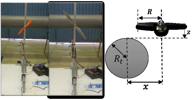
4

Wall effect.
 Last, the experimental results of the Fig. 1.c shows that the wall effect can be con-
sidered negligible following the assumption of the helicopters theory which assumes
that the flow is perpendicular to the rotor plane.

Paper contribution.
 Although these previous results could be a starting point to model the aerodynamic
effects flying close to obstacles, this paper goes beyond trying to model not only the
aerodynamic effect over or under an obstacle, but also how this effect starts to be sig-
nificant as a rotor approaches them.
 Moreover, due to this paper is focusing on an I&M of an oil and gas industry this
paper also models the behaviour of rotors working close to tubular obstacles like pipes.
 Next section presents the methodology followed by the experimental results of the
different cases of study of this research.

3 Experimental Modelling

 Fig. 2. Test configuration and nomenclature

Due to the typical scenario in an oil and gas inspection application includes two differ-
ent obstacles, which are flat surfaces like grounds or ceilings and tubular obstacles like
pipes, these will be the one taken into consideration on this work. Moreover, in contrast
to the classical studies that only model the aerodynamic effect like a rotor working
under or over an obstacle, this paper also models the transition part when the rotor
approaches the obstacle from the rotor it is out of the effect till it is fully affected by it.
These results will be obtained through several experiments in a test stand which is able
to measure the thrust of the rotor. In the rectangular obstacle, the area in which the
different experiments are carried out are represented in the blue areas in Fig. 2. This
area starts when the center of the rotor placed at one radius of distance in the axis of
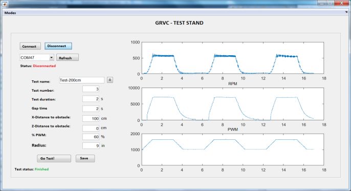
5

the Fig. 2 and the propeller is completely out of the obstacle (point A) and finish when
the propeller is full placed over the obstacle (point B). The experiments in the tubular
obstacles are also accomplished in the blue areas taking into account the symmetry
conditions of the problem.

Experimental procedure.
 In order to grant that the results can be compared between them, it has been neces-
sary to define an experimental procedure common to all the experiments. In this re-
search, a test bench with a load cell connected to an Arduino Mega 2560 which maintain
a serial communication with a computer running MATLAB. In this PC, there is a
graphic user interface (GUI) in which it is possible to define the experimental setup.
Fig. 3 shows the program developed to unify the experimental conditions and the set-
tings used during the experiments.

 50

 40 Dat
 aA
 30

 20

 10

 0
 0 5 10 15 20 25 30

Fig. 3. Graphic user interface developed and used during the experiments.

 Fig. 3 shows the GUI used to unify the experimental procedure, this system allows
to select the most important variables of the experiment and show the results in the
graphs placed on the right side. Some of the values which can be settable are the
% of the rotor, the number of iteration, the time in steady state and the gap be-
tween the different experiments.

3.1 Aerodynamic effects close to flat surfaces
Following the experimental procedure presented before, the ground and the ceiling ef-
fect has been studied taking into account the behaviour when the rotor approaches the
obstacle. Due to the results of these aerodynamic effects have been previously studied
in the literature and by the authors when the rotor is completely under the aerodynamic
effect, it will be assumed that the effect follows the classical models because they have
been validated previously. Thus, the theoretical model the ground effect presented in
[18] and the experimental one of [19] for the ceiling effect will be used to create the
aerodynamic effect map. The expression of both models are presented as follows:
6

 { } 1
 Ground Effect: = 1 2
 { } 1− ( )
 16
 { } 1
 Ceiling Effect: = 1 2
 { } 1− ( )
 1 2 +
 Where the acronyms , , and are “in/out ceiling/ground effect”
respectively. is the radius of the rotor and is the distance between the rotor plane to
the obstacle as it is presented in the Fig. 2, in this case, we assume that the rotor is
totally over the obstacle. The values of 1 and 2 were obtained through an experi-
mental least square approach, in this case 1 = 6.924 −1 and 2 = 0.03782 .
 Last, the experimental results of Fig. 3 show how the thrust changes when the rotor
approaches the obstacle.

 Fig. 4. Ground and ceiling effect with a flat surface - experimental results

 The results of Fig. 4 show the differences of the aerodynamic effect when a rotor
approaches ground or ceiling obstacles. These results show that for the tested distances
the ground effect is stronger than the ceiling which is in line with the previous results
of the literature as it is presented in Fig. 1 in the Section 2.2. This figure shows the
evolution of the ground and the ceiling effect across the longitudinal coordinate but also
combines it with the vertical one.

3.2 Aerodynamic effect close to pipes

 The results of the aerodynamic effect which arises when a rotor is working very
close to tubular objects like pipes are very relevant from the I&M of oil and gas industry
point of view. In this case, it is assumed that the results will be symmetric due to the
geometry of the problem, thus, the experiments will be tested with a rotor approaching
the middle point of the tube as it is presented in Fig. 2 and following the experimental
procedure previously established the results are shown in Fig. 5
7 Fig. 5. Tube-ground and tube-ceiling effect - experimental results Fig. 5 shows that the behaviour of the aerodynamic effect is the same respect to the obstacle, however, the magnitude is lower. This is the expected results because the wake of the rotor has more space and the changes in the flow field are lower. Never- theless, during the experiments it was clear that the aerodynamic effect produced by a pipe not only depends on the relative position of the rotor respect to the pipe, but also depends on the relative size between them. A single test with two different configura- tions was accomplished and their results are shown in Fig. 6 where it is possible to observe that if the rotor is very small respect to the pipe (blue line) the aerodynamic effect is more similar to the effect close to a flat surface and vice versa. Fig. 6. Comparison with different relation between the pipe and rotor diameter However, in this paper the aerodynamic map and the most of the test have assumed that the diameter of the rotor is 9 inches and the diameter of the pipe is 6 inches because it is the size of the most of tubes in an oil and gas industrial environment and it also was the recommendation of the industry end-users.
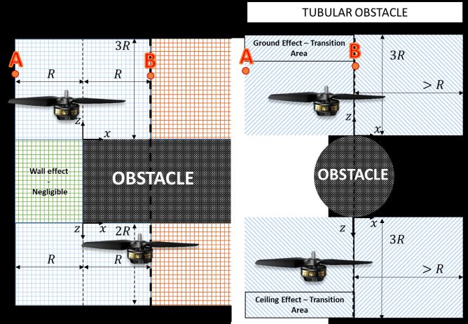
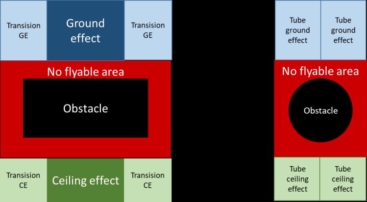
8

4 Mapping

Once the aerodynamic effects close to flat surfaces and tubes have been experimentally
tested, the next step is to combine them in an aerodynamic map which could be used in
a future to improve the control strategies or the planning methods taking into account
this aerodynamic effect map.

4.1 Assumptions

This section is focused on defining the limits to the flying area and to establish the
assumptions when the rotor is working close to different obstacles. These assumptions
are established in term of defining the flyable area during the operation and how to
solve the problem in the points which are under the influence of more than one obstacle.

Flyable area.
 Fig. 7 shows the flyable areas close to a flat/rectangular obstacle and a tubular one.
This area establishes the limits of the map and envelope the operation area of the aerial
platform.

 Fig. 7. Flyable area detail and forbidden zones.

 The map around these obstacles will be model as it is shown in the Fig. 8.
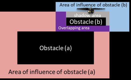
9

 Fig. 8. Sample of aerodynamic effect close to a rectangular obstacle (left) and a pipe (right)

 The flat surface where the value of the non-dimensional thrust is 0.95 is out of the
flying area but it has been defined with this value to avoid infinite elements in the plot.

Obstacle overlapping.

 The assumption to model the aerodynamic effect in the points of the map which are
affected by more than one obstacle is that it is possible to apply the principle of super-
position, however, it is assumed that the superposition method is no longer valid if one
obstacle is in the shadow of another one. This is clearly explained in the Fig. 9, where
the red area shows the influence area of the obstacle (a) and the blue area the influence
of the obstacle (b). In the section in purple, it is where the principle of superposition is
applicable and the grey zone is a shadow area and shows an area in which the aerody-
namic effect of the obstacle (a) is considered blocked by the presence of the obstacle
(b).

 Fig. 9. Obstacle overlapping and shadows conditions
10

4.2 Results
Last, this section presents the results of different aerodynamic maps in which it is rep-
resented the changes of the thrust due to the influence of the obstacles.
 Fig. 10, Fig. 11 and Fig. 12 show the results in three different scenarios which can
be used later to design different planning or control techniques.

 Fig. 10. Aerodynamic effect map with rectangular obstacles

 Fig. 11. Aerodynamic effect map with tubular obstacles

 Fig. 12. Aerodynamic effect map with rectangular and tubular obstacles
11

5 Conclusions and future applications

This paper has presented a new approach to the modelling of the aerodynamic effects
that can arise during the operation of an UAV flying close to obstacles in oil and gas
plants. This approach consists of creating an aerodynamic effects map which links the
relative position of the vehicle with the aerodynamic effect that the environment pro-
duces in this point.
 The different aerodynamic effects have been independently studied and the different
assumptions about the areas under the influence of more than one obstacle are also
presented.
 Future work related to this research will be focused on the application of this map to
design different control techniques or planning methods which take into account the
aerodynamic effects on the aerial vehicle to improve its behavior or to optimize the use
of resources like the power or time consumption during the operation. This kind of map
has a direct application in the direction of the actual application of the UAV in the
Inspection and Maintenance of oil and gas industries.

Acknowledgments

 This work has been supported by the HYFLIERS (H2020-ICT-25-2016-2017) and
RESIST (H2020-MG-2017-769066) projects, funded by the European Commission un-
der the H2020 Programme, the ARCTIC (RTI2018-102224-B-I00) project, funded by
the Spanish Ministerio de Economia y Competitividad, the ARM-EXTEND project
funded by the Spanish RD plan (DPI2017-89790-R) and the FPU Program, funded by
the Spanish Ministerio de Educación, Cultura y Deporte. A special thanks to Ricardo
Moreno for his support.

References
 1. Valavanis, K., Vachtsevanos, G.: Handbook of Unmanned Aerial Vehicles, Springer (2015).
 2. Ruggiero, F., Lippiello, V., Ollero, A.: Aerial manipulation: A literature review. In: IEEE
 Robotics and Automation Letters 3.3 1957-1964 (2018).
 3. Orsag, M., Korpela, C., Oh, P.: Modeling and control of MM-UAV: mobile manipulating
 unmanned aerial vehicle. In: Journal of Intelligent and Robotic Systems: Theory and Appli-
 cations, vol. 69, no. 1-4, pp. 227–240, (2013).
 4. Fumagalli, M., Naldi, R., Macchelli A., et al.: Developing an aerial manipulator prototype:
 physical interaction with the environment. In: IEEE Robotics and Automation Magazine,
 vol. 21, no. 3, pp. 41–50, (2014).
 5. Trujillo, M. Á., Martínez-de Dios, J. R., Martín, C., Viguria, A., Ollero, A.: Novel aerial
 manipulator for accurate and robust industrial ndt contact inspection: a new tool for the oil
 and gas inspection industry. Sensors, vol. 19, iss. 6, p. 1305, (2019).
 6. Sanchez-Cuevas, P. J., Ramon-Soria, P., Arrue, B., Ollero, A., Heredia, G.: Robotic system
 for inspection by contact of bridge beams using UAVs. Sensors, vol. 19, iss. 2, p. 305,
 (2019).
 7. https://aeroarms-project.eu/, last accessed 2019/10/03.
 8. https://www.oulu.fi/hyfliers/, last accessed 2019/10/03.
12

 9. http://www.resistproject.eu/, last accessed 2019/10/03.
10. Powers, C., Mellinger, D., Kushleyev, A., et al.: Influence of aerodynamics and proximity
 effects in quadrotor flight. Experimental robotics. Springer, Heidelberg, p 289-302 (2013)
11. Fradenburgh, E. A.: The helicopter and the ground effect machine. Journal of the American
 Helicopter Society, vol. 5, no. 4, pp. 24–33, (1960).
12. Curtiss Jr., H. C., Sun, M., Putman, W. F., Hanker Jr., E. J. Rotor aerodynamics in ground
 effect at low advance ratios. Journal of the American Helicopter Society, vol. 29, no. 1, pp.
 48–55, (1984).
13. Lee, T. E., Leishman, J. G., Ramasamy, M.: Fluid dynamics of interacting blade tip vortices
 with a ground plane. Journal of the American Helicopter Society, vol. 55, no. 2, pp. 22005–
 2200516, (2010).
14. Hayden, J. S.: Effect of the ground on helicopter hovering power required. In Proceedings
 of the AHS 32nd Forum, (1976).
15. Sanchez-Cuevas, P. J., Heredia, G., Ollero, A.: Experimental approach to the aerodynamic
 effects produced in multirotors flying close to obstacles. In: Iberian robotics conference, p.
 742–752, (2017)
16. Sanchez-Cuevas, P.J., Heredia, G., Ollero, A.: Characterization of the aerodynamic ground
 effect and its influence in multirotor control. International journal of aerospace engineering,
 vol. 2017, (2017).
17. Jimenez-Cano, A. E., Sanchez-Cuevas, P. J., Grau, P., Ollero A., Heredia, G.: Contact-based
 Bridge Inspection Multirotors: Design, Modelling and Control Considering the Ceiling Ef-
 fect. IEEE Robotics and Automation Letters, vol. 4, no. 4, pp. 3561-3568, (2019).
18. Cheeseman, I., Bennett, W.: The effect of the ground on a helicopter rotor in forward flight.
 ARC R&M 3021,(1955).
19. Sanchez-Cuevas, P. J., Heredia, G., Ollero, A.: Multirotor UAS for bridge inspection by
 contact using the ceiling effect. In: Int. Conf. on Unmanned Aircraft Systems (ICUAS), Mi-
 ami, (2017).
You can also read