AN EVAPORATIVE AIR COOLER USING A PLATE HEAT EXCHANGER
←
→
Page content transcription
If your browser does not render page correctly, please read the page content below
AN EVAPORATIVE AIR COOLER USING A PLATE HEAT
                      EXCHANGER
                  D. PESCOD 1974

                   (re-constructed by John Dartnall, 2007)
SUMMARY
A new type of air cooler using inexpensive materials, mostly plastics, has been developed in the Mechanical
Engineering Division of the CSIRO. Extensive laboratory and field tests have been made.

The unit contains a plastic plate heat exchanger, two fans, a water pump and water spray nozzles. Exhaust air from the
room being cooled is drawn over wet plates in the heat exchanger and the evaporated water is carried through with the
air and discharged outside. Evaporation of the water keeps the plates cool, and fresh air blown past the dry side of the
plates is cooled before entering the room without any increase in absolute humidity. It is possible to obtain lower
temperatures and humidities in the room than is obtainable from conventional evaporative cooling systems.

                            DIVISION OF MECHANICAL ENGINEERING

                                      TECHNICAL REPORT No TR 2

                                                ---------------------

1.   INTRODUCTION

Investigations are being made in the CSIRO Division of Mechanical Engineering with the object of
developing new forms of air conditioning which could be more economical than present forms.
Evaporative coolers are limited in performance when used on their own but when used in
conjunction with regenerative heat exchangers, either switch-bed [1] or rotary type [2] , improved
performances with low running costs are possible.
If a fixed plate type non-regenerative heat exchanger is used evaporative cooling can be effected
within the heat exchanger itself, and a compact arrangement suitable for a packaged cooler may be
designed. Plate heat exchangers made of copper or other metals with good thermal conductivities
are at present uneconomical, but a theoretical design study showed that with plastic plates of 0.25
mm or less in thickness, the effect of the thermal resistance of the plate is very small.
Investigations were made of the practical problems of manufacturing plastic plate heat exchangers,
and their performance and durability when used in packaged room coolers.
2.   THEORETICAL PRINCIPLES

The principle of operation of a small cooling unit is shown diagrammatically in Fig.l. Outside air is
blown through every second passage in the heat exchanger (the primary circuit), where it is cooled
without the addition of water vapour, and is discharged into the room. The plates of the heat
exchanger have small protrusions which promote turbulence in the air and thus increase the heat
transfer, and at the same time provide support and spacing of adjacent plates. Edges of plates are
joined together as required to seal the adjacent passages. Water is sprayed into the alternate
passages, which form the secondary circuit, and the exhaust air from the room is drawn through the

                                                           1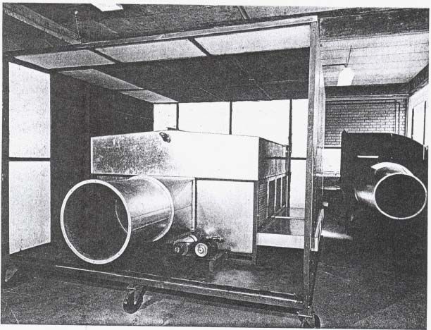
passages at the same time. Evaporation from the wet secondary surfaces cools the plates and thus
cools the primary air flow. The exhaust air carries the water vapour with it to the outside.
Because of the evaporative cooling of the plates, the temperature of the primary air at the outlet can
be lower than the temperature of the room air entering the secondary circuit. The primary and
secondary air flow rates need not be equal, and it is customary to have only about 80% of the
primary flow rate through the secondary circuit, to reduce infiltration into the conditioned space. It
is also customary to use cross flow in the heat exchanger. Counter-flow would be better but it is not
feasible with large air-to-air heat exchangers. In Fig. 2, a typical performance after a long period of
operation is shown on a psychrometric chart and is compared with evaporative cooling. Point O is
the outside condition of 36° C d.b., 23° C w.b., which may be experienced in many parts of
Australia. The line A represents the change in condition of the air as it passes through the heat
exchanger. The line RA represents the change in condition of the air while in the room, from 22° to
26° C, and the point E represents the condition at discharge to outside. Line B represents a typical
change of condition in en evaporative cooler with an effectiveness of 75%, and line RB represents
the change in condition of the air after discharge into the room, from 26° to 30° C. Thus for the
same outside conditions and the same increase in air temperature and moisture content within the
room, the new air cooler would provide a significantly lower temperature of air into the room.
The theoretical minimum temperature possible at room inlet is equal to the wet bulb temperature of
the room air, which for negligible room load or infinite air flow, is equal to the dew point of the
outside air; in this case, 17° C. The theoretical minimum temperature possible with an evaporative
cooler Is the wet bulb temperature of the outside air, in this case, 23° C.
The temperature of the air at room entry would be higher with this unit than with a vapour
compression unit; consequently a higher rate of air circulation is necessary for the same heat load in
the room. From the point of view of thermal comfort, this is an advantage. A typical vapour
compression room conditioner circulates about 125 l/s at a temperature about 10° C below room
temperature. With the new cooler, the same degree of comfort and rate of heat removal from the
room could be obtained by circulating 250 l/s at a temperature about 5° C below room temperature,
with about an eighth of the electric power consumption in the most suitable climate. In humid
conditions, the temperature difference would be less and the rate of circulation of air must be
increased accordingly.

3.   DEVELOPMENT

The first step in the development of the cooler was to find out whether plastic sheets could be
moulded into the required shape, with staggered rows of protrusions about 3 mm high and 6 mm
centres. It was not possible to draw the protrusions through holes in a perforated sheet, but drape
moulding over spikes in a wooden mould was successful, and enough sheets to make a small heat
exchanger were produced.
Methods of joining sheets at the edges were also investigated, using adhesives, clamps and welding
techniques. High frequency electronic welding was found to be the most satisfactory, but this
method cannot be applied to all plastics.
Three inexpensive plastics were tried - polystyrene, rigid PVC and cellulose acetate. All were
moulded and welded satisfactorily. A later development sealed the joints simply by immersing the
heat exchanger in a bath of special paint. This also allowed the surface to wet more readily.
Subsequent testing showed that cellulose acetate would wet readily and give the highest
effectiveness, but with extended testing it distorted badly, so polystyrene or rigid PVC was used
instead. These were found to be quite stable under severe conditions for very long periods of time.
Rigid PVC is now used exclusively as it is less brittle than polystyrene. Other plastics could be used
but usually they are more expensive.
Surface contamination of the plates by air-borne dust and by dissolved and suspended solids in the
water was studied. The effect was a slow deterioration in performance. The contamination could be

                                                  2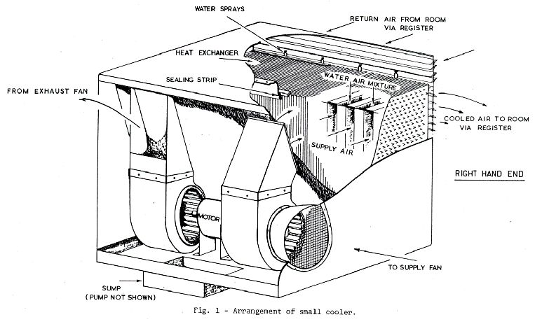
controlled by using a high water flow rate and a bleed-off to limit the salt concentration, or by
flushing the heat exchanger and sump after running periods of about 200 hours.
Water sprays also received considerable attention. In the first place, fine atomising sprays were
used, as it was thought desirable to pre-cool the return air and to keep circulation of excess water to
a minimum. The water temperature is higher than the wet bulb temperature of the return air from
the room and thus it has a sensible heating effect on the plates at entry region of the sprays and
room exhaust air. Subsequent tests showed that pre—cooling of the air was not necessary and that
high water circulation rates, up to 30 times the amount evaporated, did not give inferior results.
Evidently the sensible heating effect was offset by more complete wetting of the plates. Thus it has
been possible to use an inexpensive pump for water circulation and simple sprays with relatively
large orifices, less susceptible to blockages.
This work was first reported to the 1968 AIRAH Conference [31].
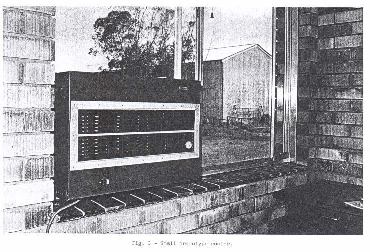
4. DESCRIPTION OF COOLER
The outward appearance of a small prototype unit is shown in Fig.3. It is approximately 675 mm
wide, 490 mm high and 740 mm deep. Air circuits through the cooler are shown in Fig.4. A large
prototype industrial unit is shown in Fig.5. It is approximately 2 m wide, 1.5 m high and 2.5 m
deep. Adjacent plates are welded together alternately, at top and bottom, and at the sides, to make a
substantially cross-flow arrangement.
This smaller unit is suitable for cooling a room with a floor area up to 20 m2, and may be mounted
in an opening in a wall, as shown, or alternatively it may be mounted inside or outside the external
wall of the building with ducts provided for air flows. Air to be cooled is drawn from outside the
building through a fan and passed through the heat exchanger and cooled before discharge into the
room. Air to be exhausted from the air conditioned space is drawn through an opening at the top of
the unit through water sprays and past the wetted sides of the heat exchanger plates, and is
discharged to atmosphere by means of a second fan. Excess water drains from the bottom of the
heat exchanger and is recirculated with make-up water, and bleed-off is provided to limit the
concentration of dissolved salts.
The heat exchanger acts as a sound attenuator, and the noise level in the room can be lower than
with conventional packaged units.
The larger unit is suitable for cooling a space with a floor area up to 200 m2. It contains six heat
exchangers, each capable of cooling up to 500 l/s of fresh air, and it is fitted with air filters at the
inlet. The fans are mounted separately. The unit delivers far more fresh air to the inside of the
building to be cooled than is provided by conventional air conditioning systems, and thus it is
particularly suitable for buildings requiring high ventilation rates, such as auditoriums, hospitals
and factories where fumes and odours are present.
5. PERFORMANCE
The performance of this type of cooler is affected by the heat load in the conditioned space as well
as outside conditions, and as it does not dehumidify the air, its cooling capacity cannot be stated for
standard conditions in the same way as vapour compression units. The most satisfactory way to rate
the performance is by “overall effectiveness”, which is defined as
outdoor dry bulb temp. - room inlet dry bulb temp.
outdoor dry bulb temp. - room outlet wet bulb temp.
This has been found to be fairly constant for a given unit and is affected mostly by air velocity and
degree of wetting and contamination of the plates. From this rating, the performance under any
given circumstances can be determined with the aid of a psychrometric chart.
3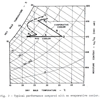
With a dry heat exchanger (without water being sprayed on the secondary surfaces) the
effectiveness relating to the primary side is
                                primary inlet temp. - primary outlet temp.
                               primary inlet temp. - secondary inlet temp.
Only dry bulb temperatures are used in this case.
In Fig.6, the effectiveness of a dry plastic plate heat exchanger and the air pressure drops are plotted
against face velocity; these results are selected from tests of seven different designs of plastic plate
heat exchanger [4] , [5] . The results are typical of turbulent flow, indicating that the protrusions are
effective in causing turbulence, since the Reynolds Numbers for air flow through plain passages of
the same dimensions indicate a laminar flow region. From the values of effectiveness obtained, the
heat transfer coefficient was calculated and the value was found to be higher than could be expected
with laminar flow plates by a factor of 4 to 5. The friction factor was also proportionately higher.
In Fig.7, overall effectiveness with wet plates, is plotted against running time for an experimental
cooling unit similar to the small prototype already described, over a period of more than 6,000
hours.
A sudden rise in effectiveness corresponds to a servicing operation, usually consisting of flushing,
draining and cleaning spray jets. By introducing continuous bleed-off, the intervals between
flushing were increased from about 200 hours to nearly 2,000 hours of operation. Later field tests
with bleed-off and higher circulation rates eliminated the need for flushing altogether.
In the above tests, the primary and secondary flows were approximately the same; tests with
reduced secondary flow indicated no significant reduction in performance until the secondary flow
was less than 80% of primary flow; for secondary flow 50% of primary flow the reduction in
overall effectiveness was approximately 10%. This demonstrates the suitability of a modified
design for rooms with a high latent load, such as bathrooms and kitchens, in which about half the
primary flow is passed back through the secondary passages and the remainder is discharged into
the room and exhausted elsewhere.
Many small prototypes have been tested for several years in various parts of Australia. Tests on the
large industrial prototype have just started.

6.   APPLICATIONS

The original prototype was of a size suitable for a single room up to 20 m2 floor area. A prototype
unit has been designed and built, using multiple heat exchangers, for factories or auditoriums. A
single unit may cool up to 200 m2 floor area. Other sizes of cooler could be designed for other
applications.
The units could be made as complete air conditioners by adding some form of heating such as
electricity or gas.
Using frequency charts of outside air conditions in Australia presented by Kowalczewski and
Cunliffe at the 1967 AIRAH Conference [61 it seems likely that this type of unit can give
satisfactory cooling in all capital cities, except Darwin, and in most inland regions. The
performance in humid tropical areas does not look so promising.
Although the construction is novel, it should be adaptable to mass production methods, and as the
material cost is relatively low, a moderate capital cost is expected if production is sufficiently large.
Power costs are low, so that the units should be attractive for use in homes and small offices.

7.   CONCLUSIONS

A new type of air cooler has been developed which can provide lower air temperatures than
evaporative coolers with no increase in absolute humidity of the air in the room, and with a capital

                                                   4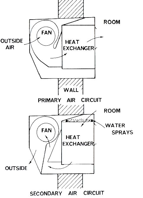
cost between that of evaporative coolers and refrigerated air conditioners. The running cost is
comparable with direct evaporative cooling.
It should be capable of giving satisfactory cooling in all areas of Australia except in the humid
tropics and hence it could be a serious competitor to refrigerated air conditioners.

REFERENCES

 [1] MORSE, R.N. - A rock bed regenerative building cooling system. Paper presented at The
Institution of Engineers, Australia, Conference on Thermodynamics and Fluid Mechanics,
Brisbane, Dec.1967.

[2] DUNKLE, R.V. - Regenerative evaporative cooling systems. Aust. Refrig.Air Condit.Heat.,
20(1), 13-23, Jan.1966.

[3] PESCOD, D. - Unit air cooler using plastic heat exchanger with evaporatively cooled plates.
Aust.Refrig.Air Condit.Heat., 22(9), 22—26, Sep.1968.

[4] CHAN, C.Y.L. - Performance tests of model plate heat exchangers with wetted plates. CSIRO
Division of Mechanical Engineering, Internal Report No.120, Mar.1973.

[5] PESCOD, D. — Performance of air-to—air heat exchangers with moulded plastic plates. CSIRQ
Division of Mechanical Engineering, Internal Report No.121, May 1973.

[61 KOWALCZEWSKI, J.J. and CUNLIFFE, D.W. - Frequency charts of outside air conditions -
application to air conditioning. Aust. Refrig.Air Condit.Heat., 21(10), 22—37, Oct.1967.

                            Figure 1: Arrangement of small cooler.

                                               5
Figure 2: Typical performance compared with an evaporative cooler.
Figure 3: Small prototype cooler.
6Figure 4: Air circuits through cooler.
Figure 5: Large prototype cooler being set up for tests.
7Figures 6 and 7 - missing :
Diagrams of the nature referred to are included in the references below:
PESCOD DONALD. - A Heat Exchanger for Energy Saving in an Air Conditioning Plant.
ASHRAE Transactions 1979, 85 (Part 2), 238 – 251.
PESCOD D. – Effects of Turbulence Promoters on the Performance of Plate Heat Exchangers.
Chapter 22 of “Heat Exchangers: Design and Theory Sourcebook”. Afgan, N. H. and Schlunder, F.
U. (eds.). Washington, McGraw-Hill, 1974, pp. 601-615.
8You can also read