Remote Outdoor Webcam Installation with Temperature and Humidity Monitoring - Melbourne Linux Users Group - MLUG
←
→
Page content transcription
If your browser does not render page correctly, please read the page content below
Remote Outdoor Webcam Installation with
  Temperature and Humidity Monitoring
       Melbourne Linux Users Group

               29 March 2021
               By: Rick Miles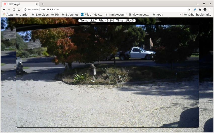
Specifications:

●
    Inexpensive SBC with small form factor and good wireless
    capabilty.
●
    Open source software.
●
    Inexpensive UVC standard webcam.
●
    Ability to integrate environmental sensor(s).
●
    Easily accessed via lan by computers and android devices.
●
    Installation in a sealed, ventilated, insect proof enclosure.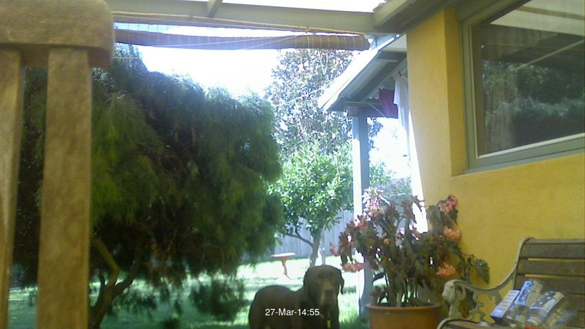
Software Required:
●
    hawkeye, “a simple, robust, easy to use USB webcam
    streaming web server which uses MJPEG as the video codec”.
●
    i2c-tools
●
    Bc
●
    imagemagick
●
    wiringPi
●
    bash and gcc
●
    Current installation uses a Raspberry Pi Zero W running 2021-
    01-11-raspios-buster-armhf-lite.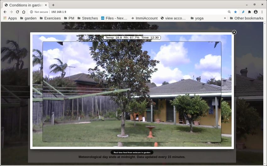
Project Schematic
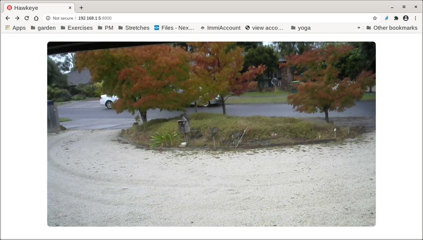
Example of remote webcam live stream
Live stream from weather station running hawkeye showing temperature, humidity and
time of data reading displayed in a Fancybox popup.
Fixing glass to enclosure viewport

                           The remote webcam will be
                           installed outdoors. In order to
                           prevent insects taking up
                           residence a piece of 1mm
                           picture frame glass is placed
                           over the webcam viewport
                           and flywire is placed over the
                           ventilation holes. Both are
                           fixed in place with 2 part
                           epoxy.

                           Note the power supply barrel
                           jack installed in the top right
                           side of the enclosure.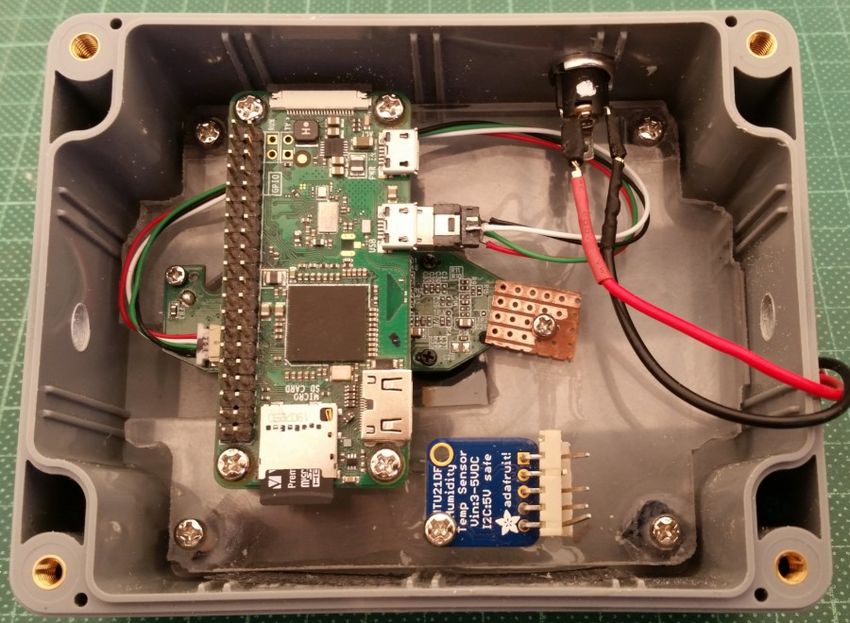
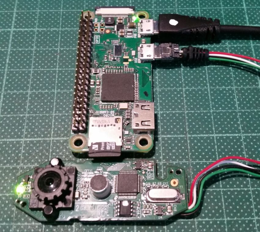
Connecting webcam to Raspberry Pi Zero W

                       The C270 circuit board was removed
                       from its enclosure and the usb cord was
                       cut off leaving 200mm still attached. The
                       cord was stripped leaving 4 wires which
                       were soldered to an Adafruit DIY Micro-B
                       USB Plug. Refer to the schematic for
                       correct wire colours.

                       Black out the webcam LED to prevent
                       reflection in webcams glass viewport.
Fixing webcam into enclosure

                      The webcam circuit board is fixed
                      onto a piece of perspex over an
                      opening large enough to allow for
                      ventilation. A screw was used
                      through an existing hole on one
                      end. The other end was clamped
                      in place with a piece of vero
                      board.

                      Spacers are used to hold the
                      perspex high enough so that the
                      camera’s lense does not come in
                      contact with the viewport glass .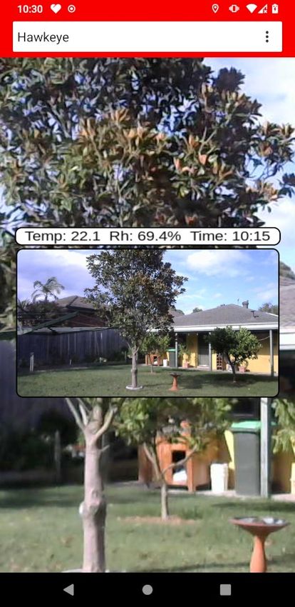
Raspberry Pi Zero and HTU21 mounted in enclosure

                                   The perspex plate is
                                   secured to the enclosure
                                   bosses with 3mm screws
                                   and the Raspberry Pi Zero
                                   and HTU21 have been
                                   secured to their standoffs
                                   with 3 mm screws

                                   Holes in left and right side
                                   of enclosure are for
                                   M6X20mm stainless steel
                                   mounting bolts.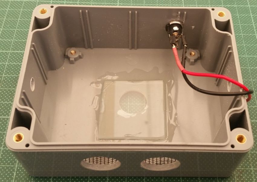
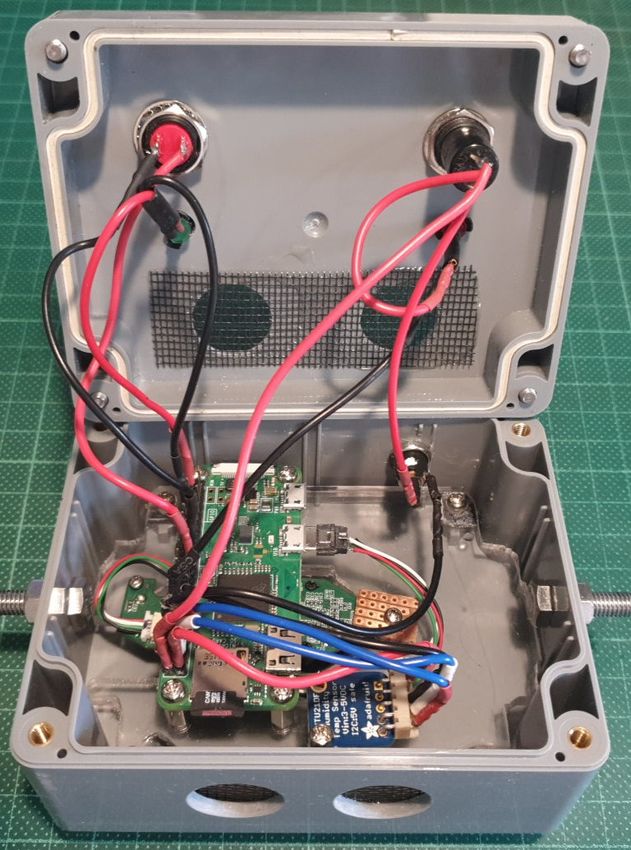
View with back cover and wiring in place

                   Left to right on the inside of the enclosure
                   cover: the momentary pushbutton shutdown
                   switch with green 5mm LED mounted in a
                   black plastic bezel and the push button
                   latching on/of switch with red LED in plastic
                   bezel.

                   Wires to switches and LEDs were soldered.
                   Wires to pins were connected using soldered
                   female crimp pins wrapped in shrink wrap.

                   Resistors were soldered inline to wires and
                   wrapped in shrink wrap.
Setting up the HTU21 Sensor The HTU21sensor will be accessed as an I2C device on the Industrial IO bus which will simplify access to humidity and temperature readings. The HTU21 breakout board is connected as shown on the schematic.
Enabling the HTU21 Sensor

Install i2c-tools and then add ‘i2c-dev’ to /etc/modules to load the i2c-dev module at
boot.

root@rpi5: echo 'i2c-dev' >> /etc/modules

Open /boot/config.txt. Uncomment the line ‘dtparam=i2c_arm=on’ and add the line
‘dtoverlay=i2c-sensor,htu21’.

# Uncomment some or all of these to enable the optional
hardware interfaces
dtparam=i2c_arm=on
dtoverlay=i2c-sensor,htu21
# dtparam=i2s=on
# dtparam=spi=on
Confirm HTU21 Sensor is an IIO device
Upon reboot, use the command ‘i2cdetect -y 1 to check that the htu21 device has
been loaded as an Industrial IO (iio) device.

root@rpi5: i2cdetect -y 1
     0 1 2 3 4 5 6 7                  8    9    a    b    c    d    e    f
00:          -- -- -- -- --          --   --   --   --   --   --   --   --
10: -- -- -- -- -- -- -- --          --   --   --   --   --   --   --   --
20: -- -- -- -- -- -- -- --          --   --   --   --   --   --   --   --
30: -- -- -- -- -- -- -- --          --   --   --   --   --   --   --   --
40: UU -- -- -- -- -- -- --          --   --   --   --   --   --   --   --
50: -- -- -- -- -- -- -- --          --   --   --   --   --   --   --   --
60: -- -- -- -- -- -- -- --          --   --   --   --   --   --   --   --
70: -- -- -- -- -- -- -- --

If the letters UU are displayed as above instead of the number 40 the HTU21 is set
up as an iio device and can be found on the iio bus
Get data from the HTU21 Sensor The HTU21 is the only iio device in this setup. It will present on the iio bus as device0. The current temperature and humidity are provided in the files in_temp_input and in_humidityrelative_input. root@rpi5: ls /sys/bus/iio/devices/iio\:device0 battery_low in_humidityrelative_input of_node sampling_frequency_available dev in_temp_input power subsystem heater_enable name sampling_frequency uevent The command ‘cat’ will return the current temperature and humidity. The Industrial I/O ABI requires that temperature and humidity values are to be returned on a scale of 1000. The temperature is 29.92 degrees celsius and the humidity is 38.10% root@rpi5: cat /sys/bus/iio/devices/iio:device0/in_temp_input 29920 root@rproot@rpi5: cat /sys/bus/iio/devices/iio:device0/in_humidityrelative_input 38100
Install and configure Hawkeye webcam server
●
    Hawkeye is a lightweight webcam server compared to mjpg-streamer. I did
    not consider motion an option although with a motion sensor added to this
    installation I could take pictures of any movement in the view range.
●
    Hawkeye was developed by Igor Partola for personal use on a Raspberry Pi.
    It is available at https://github.com/ipartola/hawkeye. The README.md
    provides links to debs as well as source code. I have built and installed the
    two debs hawkeye-dbgsym_0.7_armhf.deb and hawkeye_0.7_armhf.deb
    from the source on the Raspberry Pi Zero W used in this project.
●
    For anyone interested, it is possible to compile the Hawkeye source for use
    on other SBC’s. I have Hawkeye running on the Lemaker Banana Pro that
    runs my weather station and weather station server. After compiling I had to
    manually put together, create and then install the Slackwarearm package.
●
    If anyone needs more info on how to get Hawkeye running on a non-
    systemd system contact me on the MLUG list.
Install and configure Hawkeye webcam server Once installed, Hawkeye’s configuation file can be found at /etc/hawkeye/hawkeye.conf. The Raspberry Pi Zero has been given a static IP address. The address in the config file has to be edited from localhost to 192.168.1.5. Also the webcam resolution and frame rate is modified to maximum available on the Logitech C270. # IPv4 and IPv6 addresses and hostnames are supported. host = 192.168.1.5 # Secure default. port = 8000 fps = 20 width = 1280 height = 720 # Only has an effect if format is set to yuv Quality = 80 After editing the config, file restart hawkeye with ‘systemctl restart hawkeye’. The hawkeye webcam stream can now be accessed at 192.168.1.5:8000.
Real time stream from the Hawkeye webcam server
Create a background image and data label
The Hawkeye server provides a blank webpage with the webcam stream in the centre and
without the temperature and humidity. With ‘bc’ installed for simple math and ‘imagemagick’
installed to work with images a bash script ‘mk-background.sh’ is used to create a
background image and a label containing the temperature, humidity and time data was read.
The script is run by cron every 15 minutes to provide a fresh background and fresh data.

  # Blink green LED to show script is running.
  /usr/local/bin/wc_jobs -b
  #
  # Get current humidity and create a humidity variable.
  in_humid=$(cat/sys/bus/iio/devices/iio:device0/in_humidityrelative_input)
  humid=$(echo "scale=3; $in_humid / 1000" | bc)
  humid=$(printf "Rh: %.01f%%" $humid)
  #
  # Get current temperature and create a temperature variable.
  in_temp=$(cat /sys/bus/iio/devices/iio:device0/in_temp_input)
  temp=$(echo "scale=3; $in_temp / 1000" | bc)
  temp=$(printf "Temp: %.01f" $temp)
Create a background image and data label
   # Grab a webcam image, modify and create a background image.
   wget -O /tmp/output.png http://192.168.1.5:8000/still/0 2> /dev/null
   #
   convert /tmp/output.png -quality 25 \
   -gravity North -chop 0x50 -gravity South -chop 0x50 \
   /var/lib/hawkeye/www/background.png 2> /dev/null
   #
   # Create an information label as a .png image.
   convert -background white -fill black -font Liberation-Sans \
   -pointsize 22 label:"\ $temp $humid Time: $(date "+%H:%M") " \
   /var/lib/hawkeye/www/header.png

This script saves both images to /var/lib/hawkeye/www. The complete mk-background.sh
script is provided in Addendum 1.

To run the script every 15 minutes append the following line to root’s crontab.
           */15 * * * * /usr/local/bin/mk-background.sh 1> /dev/null
Edit /var/lib/hawkeye/www/index.html
Open /var/lib/hawkeye/www/index.html and insert the CSS on this slide and the next
slide directly above the HTML tag .
body{
background-image: url('background.png');
background-size: cover;
-webkit-background-size: cover;
-moz-background-size: cover;
-o-background-size: cover;
background-repeat: no-repeat;
background-position: center center;
}Edit /var/lib/hawkeye/www/index.html
section{
position: absolute;
top: 50%;
left: 50%;
margin-right: -50%;
transform: translate(-50%, -50%)
}
img{
border-radius: 10px;
border: 2px solid black;
}Edit /var/lib/hawkeye/www/index.html (continued) Add the following lines directly below the HTML tag . Add the following line directly above the HTML tag . The next time the remote webcam is accessed at 192.168.1.5:8000 the webpage will present with the most recent image of the webcam’s field of view as a background as well as the most recent temperature and humidity at the remote webcam’s location displayed in a label.
Live stream with webpage background and data label
Live stream displayed in the LineageOS Jelly browser
C program, wc_jobs, carries out system tasks
While turning on and blinking a LED could be accomplished in a bash script, a system can
not be shut down with a bash script. The C program wc_jobs is used to shut down the
system as well as turn on or blink the green LED.

 ‘wc_jobs -u’ turns on the green LED.
 ‘wc_jobs -d’ turns off the green LED.
 ‘wc_jobs -m’ monitors the shutdown switch and shuts down the system when it is
 pressed.
 ‘wc_jobs -b’ blinks the LED 12 times.

It shouldn’t be necessary to discuss switching LEDs on and off. However, ‘wc_jobs -m’
involves changing the logic level of a gpio pin and deserves a closer look.
C program, wc_jobs, carries out system tasks

Pin 13 is configured as an input pin and pulled up. This makes the logic state of the
pin HIGH (1). When the momentary switch is pressed, pin 13 is shorted to Ground
which changes the pin’s logic state to LOW (0). When the logic state changes to
LOW the command ‘/sbin/shutdown -h now’ is run.

The code for ‘wc_jobs -m’ follows on the next slide.
C program, wc_jobs, carries out system tasks
case 'm':                // Monitor for momentary switch press
                         // and shut down system if pressed.
   wiringPiSetup();
   pinMode(SHTDWN_PIN, INPUT);
   pullUpDnControl (SHTDWN_PIN, PUD_UP);
   for(;;)
   {
       int killval = digitalRead(SHTDWN_PIN);
       if (killval == 0)
           {
               system("/usr/local/bin/wc_jobs -b");
               system("/sbin/shutdown -h now");
           }
   }

  The complete source code for wc_jobs is provided in Addendum 2.
The End? Not quite!
Setting up a pyroelectric infrared (PIR) Motion Sensor
A couple days ago I picked up an Arduino compatible PIR sensor at Jaycar. Too late to
make the cut and be included in the Remote Webcam Mark I but I couldn’t resist testing
how it could be integrated into a future iteration of this project. Jaycar does not provide
much in the way of documentation. It appears to be a clone of the HC-SR501 and you
can find information here https://lastminuteengineers.com/pir-sensor-arduino-tutorial/.
                        This sensor will run on 4.5-12VDC. Its
                        logic voltage (output) is 3.3VDC out. This
                        is compatible with the Raspberry Pi Zero’s
                        GPIO pins, i.e. 3.3VDC.
                        I can use the shutdown switch code to
                        monitor the sensor but in this instance the
                        GPIO pin will be input, pulled down LOW
                        (0) with the sensor pulling it HIGH (1)
                        when motion is detected. I have measured
                        the logic voltage at ~3.3V but will put a
                        resistor between the sensor and the GPIO
                        pin as a precaution.
Setting up a pyroelectric infrared (PIR) Motion Sensor
This is the code added to wc_jobs that pulls a GPIO pin down (0) and waits for it to be
pulled up (1) by the PIR sensor. When pulled up it runs a script get-image.sh.
case 's': // Monitor input pin connected to a
// PIR sensor and grab a still image
// when sensor detects movement.
wiringPiSetup();
pinMode(SNAP_PIN, INPUT);
pullUpDnControl (SNAP_PIN, PUD_DOWN);
for(;;)
{
delay(50);
int snapval = digitalRead(SNAP_PIN);
if (snapval == 1)
{
system("/usr/local/bin/get-image.sh");
system("/usr/local/bin/wc_jobs -b");
}
}Setting up a pyroelectric infrared (PIR) Motion Sensor A short bash script ‘get-image.sh’ will be run by ‘wc_jobs -s’ when motion is detected. It will grab an image from the webcam and name that image using a time stamp. #!/bin/bash # /usr/local/bin/get-image.sh RM20210326 # Obtains an image from webcam when PIR Sensor is triggered, # adds a timestamp to the image and saves the image named # with the timestamp. # wget -O /tmp/output.png http://192.168.1.6:8000/still/0 2> /dev/null # timestamp=$(date +%d-%b-%R) # convert /tmp/output.png -pointsize 20 -fill white \ -gravity South -annotate +0+25 "$timestamp" \ /tmp/$timestamp.png A preliminary test was undertaken by setting a spare Raspberry Pi Zero W with webcam and the PIR sensor up on the veranda dining table and calling the dog.
Setting up a pyroelectric infrared (PIR) Motion Sensor
Setting up a pyroelectric infrared (PIR) Motion Sensor
In the image on the previous slide our dog was ~3 metres from the sensor when it detected
his movement. The acacia behind the dog was ~4 metres away from the sensor. The sensor
detected the acacia branches moving in the breeze.

The maximum view angle of the sensor is said to be 110 °. However, after connecting an
LED to the 3.3V output and putting my hand in different locations it seems the maximum view
angle is more like 150 °-160 °. I will have to play with the adjustments and possibly tape over
part of the fresnel lense to narrow the sensor view angle before I decide if this will be suitable
for use with my remote webcam.
Bill of Materials
    Logitech C270 Webcam                                   Kogan.com
    Raspberry Pi Zero W                                    Core Electronics   CE04754
    Adafruit HTU21DF Temperature + Humidity Sensor         Core Electronics   ADA1899
    USB DIY Connector Shell-Type Micro-B Plug              Core Electronics   ADA1390
    5VDC 13W Regulated Plugpack (switchmode)               Ocean Controls     PLP-009
    PIR Motion Detector Module                             Jaycar             XC4444
    115x90x55 ABS Sealed Enclosure                         Jaycar             HB-6124
    SPST N/O Momentary Action Switch                       Jaycar             SP0700
    SPST Pushbutton - Black Actuator – Latching            Jaycar             SP0718
    5mm Green Diffused LED                                 Jaycar             ZD0170
    5mm Red Diffused LED                                   Jaycar             ZD0150
    5mm LED Clips Black                                    Jaycar             HP1102
    M3 x 15mm Tapped Metal Spacers (standoffs)             Jaycar             HP0904
    M3 x 10mm Steel Screws                                 Jaycar             HP0403
Wire, resistors, crimp pins, etc. were from personal stock or left over from other projects.
Note that perspex or glass cut-offs can be sometimes be obtained for free or inexpensively
from glaziers or plastic fabricators.
This is the end!
If you haven’t asked a question yet, now is the time ....
and thank you for your kind attention.Addendum 1: mk-background.sh #!/bin/bash # /usr/local/bin/make-background.sh RM20210221 # Used with remote webcam installation. # Creates a background image for Hawkeye's server index.html # and a data label showing current temperature, humidity # and time reading was taken. # # Blink green LED to show script is running. /usr/local/bin/wc_jobs -b # # Get current humidity and create a humidity variable. in_humid=$(cat/sys/bus/iio/devices/iio:device0/in_humidityrelative_input) humid=$(echo "scale=3; $in_humid / 1000" | bc) humid=$(printf "Rh: %.01f%%" $humid) #
Addendum 1: mk-background.sh (continued)
# Get current temperature and create a temperature variable.
in_temp=$(cat /sys/bus/iio/devices/iio:device0/in_temp_input)
temp=$(echo "scale=3; $in_temp / 1000" | bc)
temp=$(printf "Temp: %.01f" $temp)
#
# Grab a webcam image, modify and create a background image.
wget -O /tmp/output.png http://192.168.1.5:8000/still/0 2> /dev/null
#
convert /tmp/output.png -quality 25 \
-gravity North -chop 0x50 -gravity South -chop 0x50 \
/var/lib/hawkeye/www/background.png 2> /dev/null
#
# Create an information label as a .png image.
convert -background white -fill black -font Liberation-Sans \
-pointsize 22 label:"\ $temp $humid Time: $(date "+%H:%M") " \
/var/lib/hawkeye/www/header.png
Addendum 2: wc_jobs.c
/*/////////////////////////////////////////////////////////////
/ wc-jobs.c RM20210221 compile to wc_jobs
/ gcc -Wall wc-jobs.c -o wc_jobs -l wiringPi
/
/ This program is used to control Gpio pins in order to power
/ up/down a green LED, blink the green LED, monitor a pin that
/ shuts down the system when a shut down button is pressed.
/ Usage: ws_jobs [OPTION]
/ -u, Power up the green LED
/ -b, Blink the green LED
/ -d, Power down the green LED
/ -m, Monitor the shutdown pin
/ -s, Monitor PIR sensor pin
/
/////////////////////////////////////////////////////////////*/
Addendum 2: wc_jobs.c (continued)
#include
#include
#include
#include
#include
#define LED_PIN 29      //   The green LED is connected pin 25.
#define SNAP_PIN 7      //   Pin 7 set INPUT DOWN when pulled up
                        //   a still image will be taken from
                        //   the webcam.
#define SHTDWN_PIN 13   //   Pin 13 is set INPUT UP, 1, when it is
                        //   is pulled DOWN, 0, with a button press
                        //   the system is shutdown.

int main(int argc, char *argv[])
{
   int optchar;
Addendum 2: wc_jobs.c (continued)
while((optchar = getopt (argc, argv, "ubdms")) != -1)
{
switch (optchar)
{
case 'u': // Turn on green LED.
wiringPiSetup();
pinMode(LED_PIN, OUTPUT);
digitalWrite(LED_PIN, HIGH);
break;
case 'd': // Turn off green LED.
wiringPiSetup();
pinMode(LED_PIN, OUTPUT);
digitalWrite(LED_PIN, LOW);
break;Addendum 2: wc_jobs.c (continued) case 'b': // Blink green LED. wiringPiSetup() ; pinMode(LED_PIN, OUTPUT); int count_blinks = 1; while(count_blinks
Addendum 2: wc_jobs.c (continued)
case 'm':            // Monitor for momentary switch press
                     // and shut down system if pressed.
   wiringPiSetup();
   pinMode(SHTDWN_PIN, INPUT);
   pullUpDnControl (SHTDWN_PIN, PUD_UP);
   for(;;)
   {
       int killval = digitalRead(SHTDWN_PIN);
       if (killval == 0)
       {
           system("/usr/local/bin/wc_jobs -b");
           system("/sbin/shutdown -h now");
       }
   }   // Closes for loop
Addendum 2: wc_jobs.c (continued)
case 's': // Monitor input pin connected to a
// PIR sensor and grab a still image
// when sensor detects movement.
wiringPiSetup();
pinMode(SNAP_PIN, INPUT);
pullUpDnControl (SNAP_PIN, PUD_DOWN);
for(;;)
{
delay(50);
int snapval = digitalRead(SNAP_PIN);
if (snapval == 1)
{
system("/usr/local/bin/get-image.sh");
system("/usr/local/bin/wc_jobs -b");
}
} // Closes for loop
} // Closes switch
} // Closes while loop
return 0;
}You can also read