INSTALLATION & OPERATION MANUAL - IPSi2400-125-xxx - Analytic Systems
←
→
Page content transcription
If your browser does not render page correctly, please read the page content below
INSTALLATION &
   OPERATION MANUAL

   IPSi2400-125-xxx
   PURE-SINE INVERTER

An ISO9001 and AS9100 Registered Company Battery Chargers • Inverters • Power Supplies • Voltage Converters

8128 River Way, Delta B.C. V4G 1K5 Canada   T. 604.946.9981 F. 604.946.9983 TF. 800.668.3884 (US/CANADA)
                                    www.analyticsystems.com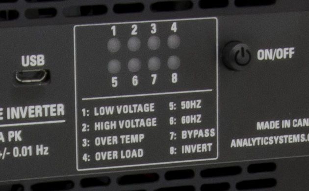
IMPORTANT & SAFETY INSTRUCTIONS
 1. SAVE THESE INSTRUCTIONS — This manual contains important safety and operating
    instructions for the inverter.
 2. Do not expose the inverter to rain or snow.
 3. Use of an attachment not recommended or sold by the inverter manufacturer may result
    in a risk of fire, electric shock, or injury to persons.
 4. Do not disassemble the inverter; take it to a qualified serviceman when service or repair
    is required. Incorrect reassembly may result in a risk of electric shock or fire.
 5. To reduce risk of electric shock, disconnect the inverter from the input power before at-
    tempting any maintenance or cleaning. Turning off controls will not reduce this risk.
 6. Never place the inverter directly above a battery; gases from the battery will corrode and
    damage the inverter.
 7. Never allow battery acid to drip on the inverter.

GROUNDING AND AC POWER CORD CONNECTION INSTRUCTIONS — Inverters
should be grounded to reduce risk of electric shock. This inverter is equipped with a chassis
grounding stud, and electric receptacles capable of accepting an equipment-grounding
conductor and a grounding plug.

LIFE SUPPORT — Analytic Systems does not recommend the use of the IPSi2400 Series
Inverters in life support applications where failure or malfunction of the product can be
reasonably expected to cause failure of the life support device or to significantly affect its
safety or effectiveness. Analytic Systems does not recommend the use of any of its products
in direct patient care. Examples of devices considered to be life support devices are neonatal
oxygen analyzers, nerve stimulators (whether used for anesthesia, pain relief, or other
purposes), autotransfusion devices, blood pumps, defibrillators, arrhythmia detectors and
alarms, pacemakers, hemodialysis systems, peritoneal dialysis systems, neonatal ventilator
incubators, ventilators for both adults and infants, anesthesia ventilators, and infusion pumps
as well as any other devices designated as “critical” by the U.S. FDA.
Introduction
The IPSi2400 Series 2400 Watt ‘Pure Sine Wave’ Inverter is designed specifically for running
sensitive electronic equipment. It produces pure sine wave AC power exactly the same as a
regular AC outlet.
The IPSi2400 Inverter is controlled by a sophisticated Digital Signal Processor (DSP) for
optimal control and the most efficient operation possible. The heavy duty Toroidal Power
Transformer steps the low voltage AC produced by the Power MosFet Transistors to either
110 or 220 VAC at either 50 or 60 Hz as well as filtering the AC output to reduce or eliminate
electrical noise that could interfere with sensitive communications equipment.
FEATURES
• ‘Pure Sine Wave’ 110 VAC / 60 Hz or 220 VAC / 50 Hz fully regulated output, exactly
the same as commercial AC.
• Crystal controlled for precise frequency (± 0.01 Hz) at either 50 or 60 Hz.
• 2400 Watts output power sufficient for a complete computer workstation and more.
• State of the art MOSFET technology and sophisticated DSP control for efficient and
reliable operation.
• Illuminated ON-OFF switch for positive indication of proper operation.
• Heavy input filtering to shield other devices sharing the same battery.
• Transformer type output to protect computers and other sensitive equipment from
surges and spikes.
• Low voltage warning and shutdown circuitry to protect the batteries.
• Over voltage and over temperature warning and shutdown circuitry to protect the
inverter.
• Short circuit protection.
• LED indicators and a buzzer to bring attention to the cause of the shutdown.
• One circuit breaker protected AC receptacle plus a hard wire terminals for easy
connection.
• Three year parts and labor warranty.
3Specifications
Input
Nominal Voltage 125 Vdc
Working Voltage 100 - 140 Vdc
Input Amps (max) 28
Input Fuse None, external fuse or breaker required
Input Connection 30 Amp, 250V Rated CSA/UL Approved Terminal Block, Red for Positive, Black for Negative
Output
Voltage 110 +/- 2 Vac 220 +/- 4 Vac
Output Amps (cont) 22.0 11.0
Output Amps (max) 28.0 14.0
Output Frequency 60.00 ± 0.01 Hz 50.00 ± 0.01 Hz
Output Type Pure Sine Wave
Output Distortion 90% @ maximum output
Temp. Range -25 to +40 deg. C° @ maximum output
Isolation Input-Output, Input-Case & Output-Case 1500Vdc Input
Length 14.6 in / 37.1 cm
Width 9.4 in / 23.8 cm (including mounting flanges)
Height 9.31 in / 23.6 cm
Clearance 1 Inch (2.5 cm) all around
Material Marine Grade Aluminum
Finish Black Powder Epoxy/Black Anodized
Fastenings 18-8 Stainless
Weight 52.5 lb / 24.0 kg
* Specifications subjects to change without notice.
Designed and manufactured by: ANALYTIC SYSTEMS WARE (1993) LTD.
8128 River Way p. 604.946.9981 f. 604.946.9983
Delta, BC V4G 1K5 Canada tf. 800.668.3884 US/Canada
www.analyticsystems.com info@analyticsystems.com Revised January 2016
4Installation
MOUNTING
Mount the unit in a DRY location. Mount the unit in a ventilated area. Allow at least 1 inch of
clearance around the unit for adequate cooling.
CAUTION: The case of the inverter is connected to AC Ground and AC Neutral to meet
regulatory requirements and to reduce the possibility of it generating any radio frequency
interference. The case must be bonded appropriately to the grounding system of the vehicle or
marine vessel. On a vehicle bond the case to the frame and on a marine vessel bond the case
to the hull. A grounding stud is provided on the front of the inverter for this purpose. To ensure
proper grounding, check the connection with an ohmmeter. The case is isolated from the DC
Input, so the DC power can be on a different ground from the AC output.
CAUTION: Do not mount the unit where explosive gases may accumulate as a slight arc may
occur when the power leads are connected, and in the unlikely event of a failure, sparks may
be generated inside the unit.
INPUT CONNECTION
Prepare a circuit breaker protected power source for the IPSi2400 Inverter, making sure the
breaker is OFF. Connect the input power to the DC IN terminal blocks using AWG12 stranded
wire. Connect the positive to the RED terminal and the Negative to the BLACK terminal.
Tip: For maximum safety, make sure the insulation of the wire butts tightly up to the terminal
so no uninsulated wire if visible. Trim the length of un-insulated wire if necessary.
CAUTION: Do Not Reverse Connect the Input Wires. This will cause serious Damage to the
Inverter and will not be covered by Warranty.
Turn on the circuit breaker and then press the ON/OFF switch to turn on the inverter. The ON/
OFF switch should illuminate and the Invert LED should come on Green. Once proper operation
is confirmed, turn the inverter OFF by pressing the ON/OFF switch again.
5OUTPUT CONNECTIONS
One standard circuit breaker protected 15 Amp AC receptacle is provided for connection. In
addition a 30 amp, 250V rated CSA/UL approved terminal block is provided for wiring to a
distribution panel. This terminal block is NOT circuit breaker protected so each device wired to
the distribution panel must have its own breaker. Ensure that the total average load of all the
devices does not exceed the continuous current rating of the unit.
CAUTION: Do not apply AC voltage to the outlets. Damage caused by this action will not be
covered under warranty.
DISCONNECTION
If you disconnect the unit to remove it for service or storage, turn the power switch on for at
least one minute after it has been disconnected to discharge the storage capacitors.
Operation
Push the On/Off control to to energize the outputs. The switch will glow to indicate the
presence of AC power at the receptacles.
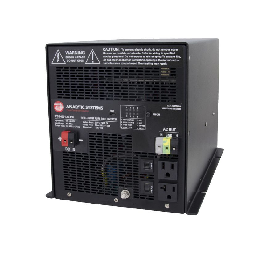
Controls and Indicators
The IPSi2400 Inverter has 8 LED indicators, a
microUSB port and a Push On / Push Off power
switch. The power switch will glow to indicate
the presence of AC power at the receptacles.
The microUSB port is used to connect the
IPSi Inverter to a laptop computer running the
PowerWizard software and can be used to
update the firmware, to adjust the low and
high voltage alarm setpoints, to choose the
output frequency (50 or 60 Hz) and to fine tune
the output voltage +/- 10% in 1 VAC steps.
Note: The microUSB port and PowerWizard software are not currently implemented for the
IPSi Inverters, but are expected to be available in mid 2016.
6There are 8 LED indicators labelled 1 through 8. Their functions are as follows:
1. Low Input Voltage: Blinks Red when the input voltage is near the lower limit for proper
operation. Glows Red when the input voltage is too low for proper operation and will be
accompanied by the Bypass LED glowing Red and the On/Off switch will not be glowing.
Check for the reason for low voltage.
2. High Input Voltage: Blinks Red when the input voltage is near the upper limit for proper
operation. Glows Red when the input voltage is too high for proper operation and will be
accompanied by the Bypass LED glowing Red and the On/Off switch not glowing. Check
for the reason for high voltage. The inverter can be damaged if the input voltage exceeds
the maximum rating, and excess voltage damage is not covered under warranty.
3. Over Temp: Blinks Red if the internal temperature of the inverter is approaching the safe
limit. The inverter will reduce its maximum power rating to try to maintain the tempera-
ture within safe limits. The LED will glow Red if the inverter is too hot to operate and
the Bypass LED will also glow Red and the On/Off switch will stop glowing. Either the
cooling fan is defective, or there is not enough air circulation for the inverter. If the fan is
running, add extra ventilation. If the fan is NOT running the inverter must be returned for
repair.
4. Overload: Blinks Red if the load on the inverter reaches the continuous rating. Solid Red
if the load on the inverter reaches the maximum rating. Reduce the load on the inverter.
5. 50 Hz: This LED will be on Green if the inverter is set for 50 Hz operation.
6. 60 Hz: This LED will be on Green if the inverter is set for 60 Hz operation.
7. Bypass: This LED will be on Green if the inverter is in Bypass mode, or on Red if the
inverter is in an Alarm condition as described above.
8. Invert: This LED will be on Green when the inverter is in normal operation.
7Limited Warranty
1. The equipment manufactured by Analytic Systems Ware (1993) Ltd. (the “Warrantor”) is warranted to be free
from defects in workmanship and materials under normal use and service.
2. This warranty is in effect for 3 years from the date of purchase by the end user.
3. Analytic Systems will determine eligibility for warranty from the date of purchase shown on the warranty card
when returned within 30 days, or
a. The date of shipment by Analytic Systems, or
b. The date of manufacture coded in the serial number, or
c. From a copy of the original purchase receipt showing the date of purchase by the user.
4. In case any part of the equipment proves to be defective, the Purchaser should do the following:
a. Prepare a written statement of the nature of the defect to the best of the Purchasers knowledge, and
include the date of purchase, the place of purchase, and the Purchasers name, address and telephone
number.
b. Call Analytic Systems at 800-668-3884 or 604-946-9981 and request a return material authorization
number (RMA).
c. Return the defective part or unit along with the statement at the Purchasers expense to the Warrantor;
Analytic Systems Ware (1993) Ltd., 8128 River Way, Delta, B.C., V4G 1K5, Canada.
5. If upon the Warrantor’s examination the defect proves to be the result of defective material or workmanship,
the equipment will be repaired or replaced at the Warrantor’s option without charge, and returned to the
Purchaser at the Warrantor’s expense by the most economical means. Requests for a different method of return
or special handling will incur additional charges and are the responsibility of the Purchaser.
6. Analytic Systems reserves the right to void the warranty if:
a. Labels, identification marks or serial numbers are removed or altered in any way.
b. Our invoice is unpaid.
c. The defect is the result of misuse, neglect, improper installation, environmental conditions, non-authorized
repair, alteration or accident.
7. No refund of the purchase price will be granted to the Purchaser, unless the Warrantor is unable to remedy the
defect after having a reasonable number of opportunities to do so.
8. Only the Warrantor shall perform warranty service. Any attempt to remedy the defect by anyone else shall
render this warranty void.
9. There shall be no warranty for defects or damages caused by faulty installation or hook-up, abuse or misuse of
the equipment including exposure to excessive heat, salt or fresh water spray, or water immersion except for
equipment specifically stated to be waterproof.
10. No other express warranty is hereby given and there are no warranties that extend beyond those described
herein. This warranty is expressly in lieu of any other expressed or implied warranties, including any implied
warranty of merchantability, fitness for the ordinary purposes for which such goods are used, or fitness for a
particular purpose, or any other obligations on the part of the Warrantor or its employees and representatives.
11. There shall be no responsibility or liability whatsoever on the part of the Warrantor or its employees and rep-
resentatives for injury to any person or persons, or damage to property, or loss of income or profit, or any other
consequential or resulting damage which may be claimed to have been incurred through the use or sale of the
equipment, including any possible failure of malfunction of the equipment, or part thereof.
12. The Warrantor assumes no liability for incidental or consequential damages of any kind.You can also read