ADVANCED LOW-COST SIC AND GAN WIDE BANDGAP INVERTERS FOR UNDER- THE-HOOD ELECTRIC VEHICLE TRACTION DRIVES - ENERGY.GOV
←
→
Page content transcription
If your browser does not render page correctly, please read the page content below
Advanced Low-Cost SiC and GaN
Wide Bandgap Inverters for Under-
the-Hood Electric Vehicle Traction
Drives

                   Kraig J. Olejniczak, Ph.D., P.E.
                   Cree Fayetteville, Inc.
                   June 8, 2016                                                    Project ID: EDT058

This presentation does not contain any proprietary, confidential, or otherwise restricted information.

A CREE COMPANY
                                           © 2015 Cree, Inc. All rights reserved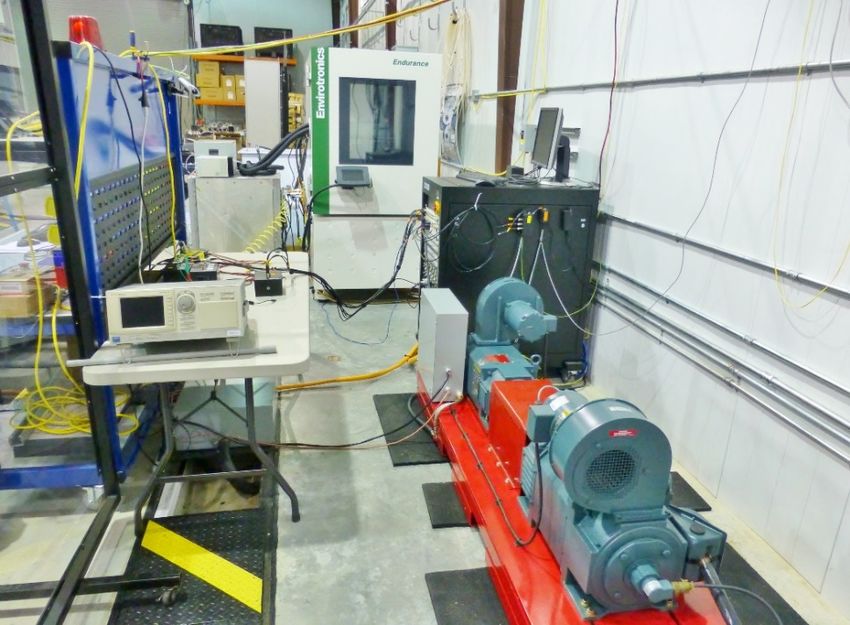
OVERVIEW                                                                        2

             Timeline                                                           Barriers
                                                        •          Unit cost ≤ $182 / 100,000
Project Start Date: October 1, 2013                     •          Obtaining high-volume cost information
Project End Date: December 30, 2015                     •          High-current GaN HEMT device avail-
Percent Complete: 100%                                             ability and maturity

             Budget                                                            Partners
                                                        •          Toyota - TRINA
Total Project Funding: $3.8M                            •          GaN Systems, Inc.
• Non-Federal Share: $2.0M                              •          National Renewable Energy
• Federal/DOE Share: $1.8M                                         Laboratory
    Funding in FY14: $1,170,086                         •          University of Arkansas National
    Funding in FY15: $ 630,046                                     Center for Reliable Electric Power
                                                                   Transmission

                                  © 2015 Cree, Inc. All rights reserved
3
                       RELEVANCE: OBJECTIVES

• Develop two independent 55 kW peak traction inverter designs (one SiC
  based and one GaN based) to showcase the performance capabilities of
  WBG power devices – namely high efficiency, increased gravimetric and
  volumetric density through high operating junction temperature capability.

• Demonstrate a substantial cost reduction from the die level to the system
  level.

• Optimize proven productized high-temperature WBG power modules for
  increased manufacturability and reduced cost.

• Application of advanced system-level packaging techniques to completely
  eliminate a vehicle’s secondary cooling loop system; utilize 85 °C rated
  capacitors, reduce interconnects, and enable increased system reliability.

• Demonstrate design robustness and reliability through extended testing of
  subsystems and systems under realistic application operating conditions.

                                 © 2015 Cree, Inc. All rights reserved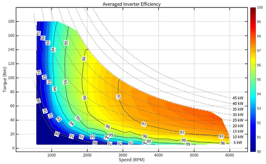
4
                     RELEVANCE: OBJECTIVES

• Application of advanced system-level packaging techniques to
  completely eliminate a vehicle’s secondary cooling loop system,
  utilize 85°C rated capacitors, reduce interconnects, and enable
  increased system reliability.

• Demonstrate design robustness and reliability through extended
  testing of subsystems and systems under realistic application
  operating conditions.

• Complete cost and manufacturing analysis to aid commercialization
  effort.

The goal of this research is to reduce traction inverter size (≥ 13.4
kW/L), weight (≥ 14.1 kW/kg), and cost (≤ $182 / 100,000) while
maintaining 15 year reliability metrics.

                              © 2015 Cree, Inc. All rights reserved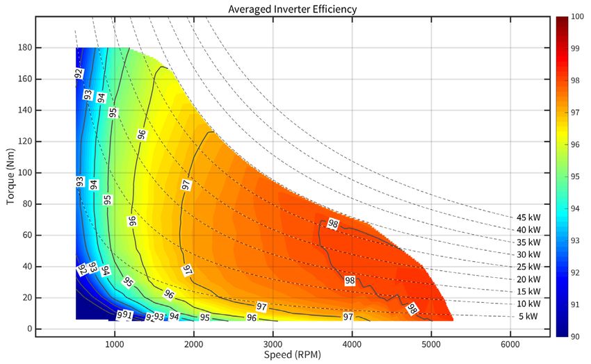
RELEVANCE                                                                5

The USDRIVE Electrical and
Electronics Technical Team’s                             Requirement                         Target
mission is to enable cost-               Continuous power output (kW)                          30
                                         Peak power output for 18 seconds (kW)                 55
effective (A), smaller, lighter          Weight (kg)                                          ≤ 3.9
(C), and efficient (E) power             Volume (l)                                           ≤ 4.1
electronics and electric motors          Efficiency                                          > 93%
                                         Unit cost for quantities of 100,000 ($)             ≤ 182
for electric traction drive                                                           200 to 450; nominal:
                                         Operating voltage (Vdc)
systems.                                                                                       325
                                         Power factor of load                                 > 0.8
                                         Maximum current per phase (Arms)                      400
The DOE EE&RE Vehicle                    Pre-charge time – 0 to 200 Vdc (sec)                   2
                                         Output current ripple – peak to peak (% of
Technologies Program Multi-              fundamental peak)
                                                                                              ≤3
Year Program Plan (2011-                 Maximum switching frequency (kHz)                    20
2015) states power electronics           Current loop bandwidth (kHz)
                                         Maximum fundamental electrical frequency
                                                                                               2

technology targets of $3.30/kW           (Hz)
                                                                                             1000
(A), 14.1 kW/kg (C), and 13.4            Minimum isolation impedance-input and
                                                                                               1
                                         phase terminals to ground (MΩ)
kW/l by 2020 to reduce                   Minimum motor input inductance (mH)                  0.5
dependence on oil through                Ambient operating temperature (⁰C)               -40 to +140
electrification of vehicle drives
with 15-year life (D).

                                    © 2015 Cree, Inc. All rights reserved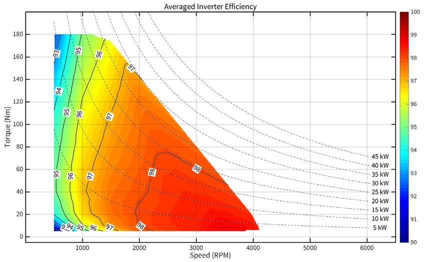
6
               TECHNICAL APPROACH / STRATEGY

• This program will develop two completely independent WBG traction
  inverters: one SiC based and one GaN based. This work will provide a
  unique, direct comparison between inverter designs using SiC and
  GaN. (Wolfspeed)

• This program will advance GaN HEMT power semiconductor device
  technology to 600 V, 100 A. (GaN Systems)

• This program will utilize advanced high performance power modules
  to achieve high power density and efficiency. (Wolfspeed)

• This program will use advanced packaging techniques (Wolfspeed)
  and active cooling technologies (Toyota, NREL) to enable the use of
  low-cost, 85 °C-rated DC bus capacitors.

• Custom, in-house HTSOI IC designs will dramatically reduce the cost
  of high temperature capable support circuitry. (Wolfspeed, abandoned)

                              © 2015 Cree, Inc. All rights reserved
Technical Accomplishments:
                  Results vs. AOI 12 Targets

A CREE COMPANY
                           © 2015 Cree, Inc. All rights reserved
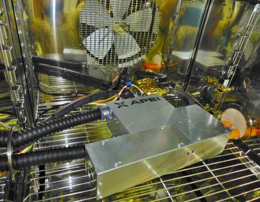
HIGH-POWER DYNAMOMETER TEST BED AT THE UNIVERSITY OF
ARKANSAS NATIONAL CENTER FOR RELIABLE ELECTRIC POWER                                                                8
                    TRANSMISSION

    A view of the test bed beside the ABB/Baldor                       The Design Cycle 2 SiC inverter inside the
  drive applying torque commands to the induction                        environmental chamber ready for test
         machine to load the interior PMSM

                                            © 2015 Cree, Inc. All rights reserved
ACCOMPLISHMENTS VERSUS PROGRAM TARGETS                                                                                 9
       No.       Requirement                       Target                    SiC-Based Inverter   GaN-Based Inverter
              Continuous power
       1
                 output (kW)
                                                      30                            √+                    √
             Peak power output for
       2
               18 seconds (kW)
                                                      55                            √+                 √
       3          Weight (kg)                       ≤ 3.9                            √                 √
       4           Volume (l)                       ≤ 4.1                            √                 √
       5            Efficiency                     > 93%                            √+              Unknown
             Unit Cost for quantities
       6
                  of 100,000 ($)
                                                    ≤ 182                           √+                    √
               Operating voltage           200 to 450; nominal:
       7
                    (V dc)                         325                              √+                    √
       8      Power factor of load                  > 0.8                            √                    √
             Maximum current per
       9
                phase (Arms)
                                                     400                             √                    √
             Pre-charge time – 0 to
       10
                 200 V dc (sec)
                                                      2                              √                    √
             Output current ripple –
                 peak to peak
       11
              (% of fundamental
                                                     ≤3                              √                    √
                     peak)
              Maximum switching
       12
               frequency (kHz)
                                                      20                            √+                   √+
             Current loop bandwidth
       13
                      (kHz)
                                                      2                             √+                   √+
             Maximum fundamental
       14     electrical frequency                  1000                            √+                   √+
                      (Hz)

                Minimum isolation
              impedance-input and
       15
               phase terminals to
                                                      1                              √                    √
                  ground (MΩ)

             Minimum motor input
       16
               inductance (mH)
                                                     0.5                             √                    √
               Ambient operating
       17
               temperature (°C)
                                                -40 to +140                          √                    √

                                     © 2015 Cree, Inc. All rights reserved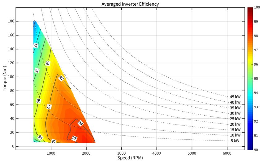
CONTINUOUS POWER OUTPUT TARGET = 30 kW                         10

• Thermal steady-state
• 59 minutes in duration
• 30 kW, 27 kVAr, 40 kVA
  @ 3480 RPM and 72 N-
  m load
• DPF ~ 0.75 lagging
• 105 °C coolant
• 140 °C ambient
• 40 °C air
• 450 VDC bus
• 16 thermocouples
  throughout the inverter
  system and averaged
                                             Source: www.omega.com
  temperatures were
  recorded every 30
  seconds

                            © 2015 Cree, Inc. All rights reserved
PEAK POWER OUTPUT FOR 18 SECONDS TARGET = 55 kW 11
• Thermal steady-state
@ 30 kW
• Load is raised to 55 kW
for a finite duration, and
then lowered back to 30
kW
• 105 °C coolant
• 140 °C ambient
• 40 °C air
• 450 VDC bus
• 56.9 kW, 47.3 kVAr,
74 kVA, 97.3%
• Test was repeated three
times dwelling for 50, 60,
and then 120 seconds
© 2015 Cree, Inc. All rights reservedMAXIMUM POWER (NO TARGET) = 81.8 kW 12
• Find the maximum continuous DYNAMOMETER LIMITED!
power for computing power
density and specific weight
• Physical limitations existed: DC
bus voltage, torque transducer,
flexible shaft couplers
• 1st attempt: 650 VDC, 6000
RPM, and 180 N-m of load
torque
• 81.8 kW, 74.7 kVArs, and 110
kVA
• DPF = 0.738 lagging
• η = 97.4%
• ~60 seconds
• dV/dt = 650/50n = 13 kV/µs !
• EMI caused communication
failures and locked up the GUI
© 2015 Cree, Inc. All rights reservedMAXIMUM POWER TARGET = 77.9 kW 13
DYNAMOMETER LIMITED!
• 2nd attempt: 600 VDC,
6000 RPM, and 180 N-m
of load torque
• 77.9 kW, 69.1 kVArs,
and
104 kVA
• DPF = 0.748 lagging
• η ≥ 97.4%
• Ran 3 times: 1, 2, and 3
minutes
• dV/dt = 600/50n = still 12
kV/µs !
• DC bus caps reached
their rating
© 2015 Cree, Inc. All rights reservedSiC INVERTER WEIGHT TARGET ≤ 3,900 G = 3.9 KG 14
Control Board,
wiring, quick
connects, and DB9 Other hardware
connectors 3%
1kV HF Cap board, 3%
SiC PS, associated AL Enclosure,
HW ports, fan
29%
EPCOS 1.1kV 30µF
Film Capacitors and
PCBs
8%
Total weight =
6,586 g or 6.59
kg (14.52 lbs.)
Bussing, Current
Sensors, Heatsinks
20%
Wolverine cold plate
- milled
HT-3000 SiC Modules 20%
and TIM
7%
© 2015 Cree, Inc. All rights reservedDOE VTP - Phase 1 Inverter Weights
Item Description Grams Qty Component Unit 15
SiC INVERTER WEIGHT AL Enclosure, ports, fan 1909
Total
1 1909 Grams
TARGET ≤ 3,900 G Wolverine cold plate - milled
HT-3000 SiC Modules and TIM
Bussing, Current Sensors, Heatsinks
1315
150
1323
1
3
1
1315
450
1323
Grams
Grams
Grams
= 3.9 KG, CONT. EPCOS 1.1kV 30µF Film Capacitors and PCBs
1kV HF Cap board, SiC PS, associated HW
90
216
6
3
540
648
Grams
Grams
Control Board, wiring, quick connects, and DB9 connectors 226 1 226 Grams
Other hardware 175 1 175 Grams
6,586 Grams
Control Board, TOTAL: 14.52 Pounds
wiring, quick
connects, and Other hardware 232.3 Ounces
DB9 connectors 5%
6%
1kV HF Cap board, Wolverine cold
SiC PS, associated plate - extruded
HW 23%
NOTE:
• Remove enclosure base, silicone sealer, lid,
ports, hardware, and fan (-1909 g)
• Remove milled Wolverine cold plate (-1315 g)
• Add Wolverine extruded cold plate (+887 g)
• Remove three of six DC bus caps (-270 g)
Bussing, Current
New TOTAL = 3,979 g = 3.98 kg (8.77 lbs.) Sensors,
Heatsinks
TARGET ≤ 3,900 g = 3.90 kg 35%
EPCOS 1.1kV 30µF
Film Capacitors
and PCBs
14%
© 2015 Cree, Inc. All rights reservedGaN INVERTER WEIGHT TARGET ≤ 3,900 G = 3.9 KG 16
Control Board,
wiring, quick
connects, and DB9 Other hardware
connectors 3%
Total weight = 630V HF Cap board, 3%
6,392 g or 6.39 GaN PS, associated
kg (14.09 lbs.) EPCOS 1.1kV 30µF AL Enclosure,
Film Capacitors and ports, fan
PCBs 30%
The SiC inverter 8%
weighs slightly
more than the
GaN inverter
because the 1 kV
HF MLCC X7R
capacitors are
physically larger
Bussing, Current
than the ones Sensors, Heatsinks
rated at 630 V. 21%
Wolverine cold plate
- milled
HT-3000 GaN Modules 21%
and TIM
7%
© 2015 Cree, Inc. All rights reservedDOE VTP - Phase 1 Inverter Weights
Item Description Grams Qty Component
Total
Unit
17
GaN INVERTER WEIGHT
AL Enclosure, ports, fan 1909 1 1909 Grams
Wolverine cold plate - milled 1315 1 1315 Grams
HT-3000 GaN Modules and TIM 152 3 456 Grams
TARGET Bussing, Current Sensors, Heatsinks
EPCOS 1.1kV 30µF Film Capacitors and PCBs
1323
90
1
6
1323
540
Grams
Grams
≤ 3,900 G = 3.9 KG CONT.
630 V HF Cap board, GaN PS, associated HW 149 3 448 Grams
Control Board, wiring, quick connects, and DB9 connectors 226 1 226 Grams
Other hardware 175 1 175 Grams
6,392 Grams
TOTAL: 14.09 Pounds
225.5 Ounces
NOTE: Control Board,
wiring, quick
• Remove enclosure base, silicone sealer, lid, connects, and Other hardware
5%
ports, hardware, and fan (-1909 g) DB9 connectors
Wolverine cold
6%
• Remove milled Wolverine cold plate (-1315 g) plate - extruded
• Add Wolverine extruded cold plate (+887 g) 25%
• Remove three of six DC bus caps (-270 g)
630V HF Cap board,
New TOTAL = 3,785 g = 3.79 kg (8.35 lbs.) GaN PS, associated
HW
12%
TARGET ≤ 3,900 g = 3.90 kg
EPCOS 1.1kV 30µF
Film Capacitors
and PCBs
15% Bussing, Current
Sensors,
Heatsinks
37%
© 2015 Cree, Inc. All rights reservedSiC & GaN INVERTER VOLUME TARGET ≤ 4.1 LITERS 18
Note: This air Wolverine Cold
plate - milled,
volume excludes 0.561, 12%
the displacement
caused by HT-3000 Modules,
0.214, 5%
internal wiring
1kV 1µ AVX X7R
and associated Ceramic Capacitors,
quick 0.098, 2%
connectors.
Total external 1.1kV 30µF EPCOS
Film Capacitors,
volume = 4.83 0.466, 10%
liters
Bus Bars (+, -, and
(excluding three phases), 0.109,
glands and 2%
connectors) Remaining volume
occupied by boards,
hardware, current
Total internal sensors, etc., 0.021,
volume = 4.66 0%
liters
With ½ the DC
bus capacitors,
Air, 3.190, 69%
4.43 liters
© 2015 Cree, Inc. All rights reservedPOWER DENSITY TARGETS ≥ 13.4 KW/L & 14.1 KW/KG 19
Design Cycle 2 SiC Inverter, 4.8 L, 6.6 kg, HT-3201-R modules
@ max. ambient and coolant temperatures
kW kVAr kVA kW/L kW/kg kVA/L kVA/kg
30 27 40.4 6.2 4.5 8.4 6.1
56.9 47.3 74.0 11.8 8.6 15.4 11.2
77.9 69.1 104.2 16.2 11.8 21.7 15.8
81.8 74.7 110.8 17.0 12.4 23.1 16.8
2020 2015
Design Cycle 2 SiC Inverter, 4.4 L, 4.0 kg, HT-3201-R modules
@ max. ambient and coolant temperatures
kW kVAr kVA kW/L kW/kg kVA/L kVA/kg
30 27 40.4 6.8 7.5 9.2 10.1
56.9 47.3 74.0 12.9 14.2 16.8 18.5
77.9 69.1 104.2 17.7 19.5 23.7 26.0
81.8 74.7 110.8 18.6 20.4 25.2 27.7
2025 2025
© 2015 Cree, Inc. All rights reservedTHEORETICAL/ACHIEVABLE POWER DENSITY TARGETS ≥ 13.4 KW/L & 20
14.1 KW/KG
Design Cycle 2 SiC Inverter, 4.8 L, 6.6 kg , HT-3201-R modules
@ < max. ambient & coolant temperatures
kW kVAr kVA kW/L kW/kg kVA/L kVA/kg
166.3 124.7 207.9 34.6 25.2 43.3 31.5
199.5 149.6 249.4 41.6 30.2 51.9 37.8
2025 2025
• With a DC bus of 650 VDC, the achievable AC output voltage is 400 V rms line to line.
• With a DC bus of 800 VDC, the achievable AC output voltage is 480 V rms line to line.
• Assume an achievable AC output current of 300 A rms and a worst-case DPF = 0.8.
• P3φ = √3 (400 [480]) (300) (0.8) = 166.3 kW [199.5 kW]
• Q3φ= √3 (400 [480]) (300) (0.6) = 124.7 kVAr [149.6 kVAr]
• The apparent power, | S3φ| = 207.9 [249.4 kVA]
Design Cycle 2 SiC Inverter, 4.4 L, 4.0 kg , HT-3201-R modules
@ < max. ambient & coolant temperatures
kW kVAr kVA kW/L kW/kg kVA/L kVA/kg
166.3 124.7 207.9 37.8 41.6 47.2 52.0
199.5 149.6 249.4 45.3 49.9 56.7 62.3
2025 2025
© 2015 Cree, Inc. All rights reservedSiC INVERTER EFFICIENCY TARGET > 93%, CONT. 21
• 650 V DC bus has a slightly lower • 200 VDC, 66 operating points
efficiency • 325 VDC, 135 operating points
• “Sweet spot” may be outside the • 450 VDC, 151 operating points
range of torques and speeds that
were tested • 650 VDC, 155 operating points
• The nominal 325 V DC bus yielded • 4 bus voltages, 507 operating points
the best overall efficiency • 6 thermal cases: 3,042 operating
• Efficiencies measured at loads < 5 points
kW are not as reliable due to Average
current signal scaling and its Peak Efficiency
Bus Voltage Efficiency
(%)
impact on the Yokogawa’s (%)
resolution being no greater than 10 200 96.7 98.7
W 325 97.0 99.0
450 96.3 98.2
650 95.2 97.9
All 4 96.3 98.9
© 2015 Cree, Inc. All rights reservedSIC INVERTER EFFICIENCY TARGET > 93% 22
Average of 6 thermal cases, 200 VDC, Mean = 96.7%, Peak = 98.4%
© 2015 Cree, Inc. All rights reservedSIC INVERTER EFFICIENCY TARGET > 93%, CONT. 23
Average of 6 thermal cases, 325 VDC, Mean = 97.0%, Peak = 99.0%
© 2015 Cree, Inc. All rights reservedSIC INVERTER EFFICIENCY TARGET > 93%, CONT. 24
Average of 6 thermal cases, 450 VDC, Mean = 96.2%, Peak = 98.2%
© 2015 Cree, Inc. All rights reservedSIC INVERTER EFFICIENCY TARGET > 93%, CONT. 25
Average of 6 thermal cases, 650 VDC, Mean = 94.9%, Peak = 97. 9%
© 2015 Cree, Inc. All rights reservedSiC INVERTER COST BREAKDOWN 26
$1,200
$1,006
$1,000 Source: Power Electronics in Electric and
Hybrid Vehicles 2014, YOLE Développement,
Cost / Unit
$800 Villeurbanne, France.
$543
$600 $491
$375
$400
$221 $192
$200
$-
2015 2016 2017 2018 2019 2020
Time Horizon
Total Price of 60 kW SiC MOSFET HEV Inverter - Agarwal Price Projections
Price of 60 kW SiC MOSFET HEV Inverter Cost Less SiC MOSFETs and
SBDs
Agarwal's Projection for SiC Costs
Source: A. K. Agarwal (DOE), “Manufacturing
DOE Inverter Target, $182 Perspective on Wide Bandgap Devices,” MRS
2014, Session T6: SiC Power Devices,
December 3, 2014.
© 2015 Cree, Inc. All rights reservedCommercialization Activity
A CREE COMPANY
© 2015 Cree, Inc. All rights reservedPATH TO PRODUCT MANUFACTURING AND
28
COMMERCIALIZATION
• Wolfspeed-led education initiative for WBG semiconductor adoption
• Building block philosophy (e.g., ONR’s PEBB initiative from many years ago)
• A highly WBG-optimized stack up that allows the user to “plug and play” in order to
show ROI / PP on either legacy product designs or new product development
• We leveraged what we learned herein to focus on Blocks 0, 4, and 5
• Block 2 and Block 5 differ only by sensor suite
• Example: Block 0 + Block 2 + Block 4 + Block 5 give use an industrial motor drive
© 2015 Cree, Inc. All rights reservedPATH TO PRODUCT MANUFACTURING AND 29
COMMERCIALIZATION, CONT.
DC+
HF HF HF
Bulk a
b
c
Current Sensors
DC-
Voltage Sensor Gate Drivers
To Block User Interface
0
A Circuit Schematic of Blocks 4 and 5
© 2015 Cree, Inc. All rights reservedPATH TO PRODUCT MANUFACTURING AND
30
COMMERCIALIZATION, CONT.
Prototype build of Blocks 4 and 5 – Block 0 is not
shown.
© 2015 Cree, Inc. All rights reservedRESPONSES TO PREVIOUS YEAR REVIEWERS’ COMMENTS 31
Questions and/or comments can be classified into one of two areas: (i.) Production costing; and
(ii.) EMI issues.
Wolfspeed’s Response: (i.) Three data points have been provided in this AMR presentation: the
BOM costs for the Design Cycle 1 SiC inverter; the BOM costs for the Design Cycle 2 SiC
inverter; and the Design Cycle 2 SiC inverter builds for N = 20, 50, 100, and 300. Further
refinement will best be done after another design cycle is complete in concert with either an OEM
or a Tier 1 supplier with a known insertion platform identified. Significant cost savings may be
achieved if the maximum ambient temperature is relaxed from 140 °C to 125 °C.
Wolfspeed’s Response: (ii.) The reviewer’s are correct in pointing out EMI challenges
associated with WBG semiconductors. But, any power device technology exhibiting “ideal power
switch” characteristics and attributes will have similar challenges. As such, the system designer
must be diligent in all aspects of grounding and shielding between, among, and within assemblies
and subassemblies. Wolfspeed had to overcame numerous obstacles to achieve the electro-
thermal targets of the program. For example, no 140 °C shielded inverter-grade cables were
found. This necessitated designing and building our own.
© 2015 Cree, Inc. All rights reserved32
COLLABORATIONS AND COORDINATION WITH OTHER
INSTITUTIONS
• OEM – Toyota. Toyota collaborated on system-level specifications
and on the design of the thermal management system.
• Device Manufacturer – GaN Systems, Inc. GaN Systems were to
fabricate and test ≥ 600 V, ≥ 50 A GaN HEMTs.
• Supporting Research Organizations
1. National Renewable Energy Laboratory – NREL performed
thermal and reliability analysis at the module- and system-
levels, respectively.
2. University of Arkansas NCREPT – UA NCREPT assisted in the
extensive characterization and testing of the traction inverter
system using a custom-designed dynamometer test bed.
© 2015 Cree, Inc. All rights reserved33
PROPOSED FUTURE WORK
• This project is complete as of December 31, 2015. Reporting continues.
• Candidate future work will be continued either through other DOE funding, or
future IR&D funding
– Package Si IGBTs within the HT-3000 package to overlay T vs. ω-plane
efficiencies with those presented herein
– Optimize the DC bussing for maximum current throughput with minimum
temperature rise
– Optimize the AC bussing for maximum current output with minimum temperature
rise
– Design using 1700 V creepage and clearance rules
– Migrate design from Gen2 to Gen3 SiC MOSFETs
– Design, build, and test efficacy of EMI enclosure for local controller
– Design, build, and test efficacy of EMI enclosure for the power stage
– Design, build, and test efficacy of output filter between inverter and traction motor
– Others…
© 2015 Cree, Inc. All rights reserved34
PROJECT SUMMARY
Source photo courtesy of Toyota.
Wolfspeed WBG Traction Inverters
Two independent designs: SiC
and GaN
>98% Peak Efficiency
- Fuel savings and reduced
emissions
$182 cost at volume
15 Year Reliability
© 2015 Cree, Inc. All rights reservedACKNOWLEDGMENTS 35
• DOE
– Susan Rogers, DOE VTO, Technology Manager, Electric Drives R&D
– Steven Boyd, DOE VTO, Technology Manager, Electric Drives R&D
– John Tabacchi, DOE NETL, Project Manager
– Amanda Lopez, DOE NETL, Contract Specialist
• Toyota/TRINA
– Kyosuke Miyagi-san, General Manager, Electronics Research Department
– Ercan (Eric) Dede, Ph.D., Manager, Lab E-2
– Feng Zhou, Ph.D., Senior Scientist
– Yuki Horiuchi, Packaging Trainee
• GaN Systems Inc.
– Girvan Patterson, President
– Howard Tweddle, Operations and Product Management
– Greg Klowak, Director of R&D
– Julian Styles, Director Sales and Marketing, Americas
© 2015 Cree, Inc. All rights reservedACKNOWLEDGMENTS 36
• NREL
– Sreekant Narumanchi, Ph.D., Power Electronics and Electric
Machines Section Supervisor
– Kevin Bennion, Power Electronics and Electric Machines
Thermal Engineer
– Gilbert Moreno, Power Electronics Thermal Engineer
– Paul Paret, Power Electronics Thermal Modeling and Test
Engineer
– Doug DeVoto, Power Electronics Reliability Engineer
• UA National Center for Reliable Electric Power Transmission
– Chris Farnell, Test Engineer
– Dr. H. Alan Mantooth, Executive Director
© 2015 Cree, Inc. All rights reservedQuestions?
A CREE COMPANY
© 2015 Cree, Inc. All rights reservedTechnical Back-Up Slides
A CREE COMPANY
© 2015 Cree, Inc. All rights reserved39
UA NCREPT
HIGH POWER
DYNAMOMETER
© 2015 Cree, Inc. All rights reservedOPERATING VOLTAGE, TARGET = 200 TO 450 VDC; 40
NOMINAL: 325 VDC
• Target met for SiC; target not met for GaN
• SiC: 200, 325, 450, and 650 VDC
• GaN: 200, 325, and 450 VDC
POWER FACTOR OF LOAD, TARGET > 0.8
• Target met for SiC; target not met for GaN
• SiC: 0.75 lagging to 1.0
• GaN: No load
MAXIMUM CURRENT PER PHASE, TARGET = 400 Arms
• Target met for SiC; target not met for GaN
• SiC: > 200 Arms was all that was required to achieve 30 kW
continuous & 55 kW peak; module met this target
• GaN: < 25 Arms
© 2015 Cree, Inc. All rights reserved41
PRE-CHARGE TIME – 0 TO 200 VDC, TARGET = 2 SECONDS
• Target met for SiC; target met for GaN
• SiC: < 1 second
• GaN: < 1 second
OUTPUT CURRENT RIPPLE – PEAK TO PEAK, TARGET ≤ 3% OF
FUNDAMENTAL PEAK
• Target met for SiC; target not met for GaN
• SiC: 2.5% of the fundamental peak
• GaN: NA
MAXIMUM SWITCHING FREQUENCY, TARGET = 20 kHz
• Target met for SiC; target met for GaN
• SiC: 20 kHz
• GaN: 20 kHz
© 2015 Cree, Inc. All rights reserved42
CURRENT LOOP BANDWIDTH, TARGET = 2 kHz
• Target met for SiC; target met for GaN
• SiC: 4 kHz
• GaN: 4 kHz
MAXIMUM FUNDAMENTAL ELECTRICAL FREQUENCY, TARGET =
1000 Hz
• Target met for SiC; target not met for GaN
• SiC: 3000 Hz
• GaN: NA
MINIMUM ISOLATION IMPEDANCE – INPUT AND PHASE
TERMINALS TO GROUND, TARGET ≥ 1 MΩ
• Target met for SiC; target met for GaN
• SiC: > 1 MΩ
• GaN: > 1 MΩ
© 2015 Cree, Inc. All rights reserved43
MINIMUM MOTOR INPUT INDUCTANCE, TARGET = 0.5 MH
• Target met for SiC; target met for GaN
• SiC: 0.55 mH tested
• GaN: 0.55 mH tested
AMBIENT OPERATING TEMPERATURE, TARGET = -40 TO +140 °C
• Target met for SiC; target not met for GaN
• SiC: +140 °C
• GaN: RT
© 2015 Cree, Inc. All rights reservedYou can also read