Analysis and Investigation of Dual-Polarized Color LED Based Visible Light Communication System

Page created by James Vega
 
CONTINUE READING
Analysis and Investigation of Dual-Polarized Color LED Based Visible Light Communication System
hv
               photonics

Article
Analysis and Investigation of Dual-Polarized Color LED Based
Visible Light Communication System
Yun-Cheng Yang 1 , Chien-Hung Yeh 1, *, Shien-Kuei Liaw 2 , Chi-Wai Chow 3 , Wei-Hung Hsu 1 and Bo-Yin Wang 1

                                          1   Department of Photonics, Feng Chia University, Taichung 40724, Taiwan; zxc706090@gmail.com (Y.-C.Y.);
                                              whhsu@fcu.edu.tw (W.-H.H.); paul19961103@icloud.com (B.-Y.W.)
                                          2   Department of Electronics and Computer Engineering, National Taiwan University of Science and Technology,
                                              Taipei 106335, Taiwan; skliaw@mail.ntust.edu.tw
                                          3   Department of Photonics, College of Electrical and Computer Engineering, National Chiao Tung University,
                                              Hsinchu 30010, Taiwan; cwchow@faculty.nctu.edu.tw
                                          *   Correspondence: yehch@fcu.edu.tw

                                          Abstract: To increase the data capacity of a light-emitting diode (LED) based visible light commu-
                                          nication (VLC) transmission, a polarization-division-multiplexing (PMD) green (G)- and blue (B)-
                                          light-based transmitter (Tx) module is demonstrated here. It was demonstrated that we can achieve
                                          1200 and 1120 Mbps VLC capacities based on dual-polarized G- and a B-LED based light wave after 3
                                          and 4 m free-space link lengths, respectively, at exceedingly low illuminance. Based on the presented
                                          VLC system, paired G-LEDs or B-LEDs with dual-polarization can also be applied on the VLC-Tx
                                          side for doubling and delivering VLC data. According to the obtained results, the largest polarization
                                          offset angle of 50◦ between two polarizers (POLs) can be allowed experimentally to provide optimal
                                          VLC traffic. Moreover, the relationships of polarization offset, the illuminance of LED and maximum
                                          achieved VLC capacity are also performed and analyzed.
         
         
                                          Keywords: visible light communication (VLC); light-emitting diode (LED); polarization-division-
Citation: Yang, Y.-C.; Yeh, C.-H.;
Liaw, S.-K.; Chow, C.-W.; Hsu, W.-H.;
                                          multiplexing (PMD); dual-polarized; energy efficiency
Wang, B.-Y. Analysis and
Investigation of Dual-Polarized Color
LED Based Visible Light
Communication System. Photonics           1. Introduction
2021, 8, 210. https://doi.org/                 Recently, mobile communication has progressed rapidly for high-speed and broad-
10.3390/photonics8060210                  band wireless data access. However, the usable wireless spectra were continuously limited
                                          and busy. Furthermore, the visible wavelength spectrum is more than 10,000 times the ex-
Received: 1 May 2021
                                          isting wireless spectrum for future signal access applications [1]. Hence, the light-emitting
Accepted: 9 June 2021
                                          diode (LED) based visible light communication (VLC) system has been presented and
Published: 10 June 2021
                                          demonstrated to provide an alternative choice for wide capacity wireless access [2,3].
                                          The LED-based VLC transmission could also provide beneficial benefits, such as cost-
Publisher’s Note: MDPI stays neutral
                                          effectiveness, a large unlicensed spectrum, energy efficiency, a long lifetime, no electromag-
with regard to jurisdictional claims in
                                          netic interference (EMI), high modulation bandwidth, and signal security [4–6]. Essentially,
published maps and institutional affil-
                                          the commercial component of phosphor-LED could only provide the achievable bandwidth
iations.
                                          of 1 to 10 MHz for VLC link, which would limit the data capacity [7,8]. To enhance the
                                          obtainable VLC capacity, the analog equalization design [8–10], parallel VLC architec-
                                          ture [11], optical color filter [12], optical multi-input multi-output (MIMO) method [13,14],
                                          wavelength-division-multiplexing (WDM) [15,16] and polarization-division-multiplexing
Copyright: © 2021 by the authors.
                                          (PDM) technologies [17–20] were studied and discussed.
Licensee MDPI, Basel, Switzerland.
                                               Utilizing 2 × 2 PDM LED-based VLC methods was proposed for doubling data
This article is an open access article
                                          rates in recent years. In 2014, Wang et al. presented 1 Gbit/s orthogonal-frequency-
distributed under the terms and
                                          division-multiplexing (OFDM) modulation rate based on a 2 × 2 red-green-blue (RGB)
conditions of the Creative Commons
Attribution (CC BY) license (https://
                                          LED-based PDM system [18]. However, they needed the avalanche photodiode (APD) to
creativecommons.org/licenses/by/
                                          detect VLC signals through a free space transmission length of 80 cm. In 2018, Hsu et al.
4.0/).
                                          demonstrated a 2 × 2 phosphor LED-based 1.4 Gbit/s OFDM VLC system with a Volterra

Photonics 2021, 8, 210. https://doi.org/10.3390/photonics8060210                                           https://www.mdpi.com/journal/photonics
Analysis and Investigation of Dual-Polarized Color LED Based Visible Light Communication System
Photonics 2021, 8, 210                                                                                         2 of 12

                         nonlinear equalization (VNE) method by using PIN PD for detection at the illuminance of
                         1000 Lux [19]. Here, the larger illuminance and complex VNE algorithm were required to
                         decode PDM and WDM VLC signal, and the wireless VLC length was not indicated. As
                         mentioned above, they required OFDM modulation format for a shorter VLC connection
                         length (or at the greater illuminance) to achieve >1 Gbit/s data rate. In 2017, Lu et al.
                         presented a hybrid PDM and RGB-WDM VLC system to achieve a 2.16 Gbit/s OFDM rate
                         through 3 m link length within 100 MHz available bandwidth [20]. However, the related
                         locations of the VLC transmitter (Tx) and receiver (Rx) were both fixed to deliver and
                         decode the VLC signal for indoor application.
                               In this demonstration, we propose and investigate a PDM-based G- and B-LED VLC
                         transmission system with an orthogonal-polarization state to double the data traffic. Here,
                         to obtain the dual-polarized VLC signals, the two orthogonal polarizers (POLs) at the
                         receiver (Rx) side can be controlled for rotation automatically to match the dual VLC
                         signals from the transmitter (Tx) site. The presented dual-polarized VLC system can
                         achieve the total modulation rate of 1200 and 1120 Mbps (VLC(Green+Blue) ) passing through
                         3 and 4 m free-space transmission lengths, respectively when the detected corresponding
                         illuminances of G- and B-LEDs are 2.4 and 0.5 lux and 5.4 and 2.3 lux. To make the
                         presented LED VLC system more flexible, we also employed paired G-LEDs and B-LEDs
                         acting as the optical transmitter (Tx) to produce dual-polarized VLC(Green) and VLC(Blue)
                         signals for alternative indoor applications, respectively. Hence, the proposed 2 × 2 PDM
                         G- and B-LED VLC system does not need any color filter for decoding signals. When the
                         VLC client is moving randomly, the two polarizers (POLs) of the Rx side are controlled to
                         match the dual-polarized VLC signals and avoid missing received signals. In addition, we
                         also perform and discuss the influence of different polarization offset at a fixed VLC rate
                         through a wireless link length of 3 and 4 m, respectively. Based on the observed results,
                         the largest offset angle of two POLs should be less than 50◦ to maintain the optimal VLC
                         modulation rate below the forward error correction (FEC) level. The presented LED VLC
                         system is for fully static scenarios in the investigation.
                               The optical wireless signal indoors might also bring a possibility of occupying by
                         unauthorized stealer. To reach the signal security in the VLC connection, applying the
                         encryption algorithm in the upper layer is one of the methods [21,22]. Due to the two mixed
                         VLCs with various modulation formats, it would also generate signal mutual interference
                         to cause a security procedure in the physics layer [23]. To decode the dual-polarized
                         signals, two orthogonal POLs with precise direction are required at the Rx side. Moreover,
                         if there are many clients with only one Rx detector in the same room for receiving the
                         dual-polarized VLC signal, the polarization of POL at each client can be controlled properly
                         to share the total capacity. As a result, compared with the previous work [17–19], the
                         presented 2 × 2 PDM G-B LED VLC system can not only achieve >1120 Mbit/s through
                         4 m wireless link at very low illuminance status but can also provide signal security in the
                         physical layer when the same color LEDs are used.

                         2. Proposed VLC Architecture and Experiment
                               Generally, to obtain a higher VLC data rate via the LED-based device, wavelength-
                         division-multiplexing (WDM) LEDs were proposed and studied [15,16]. Hence, the red
                         (R), green (G) and blue (B) LEDs could be used to serve as the optical transmitter (Tx)
                         for WDM VLC transmission at the VLC-Tx side, respectively. Here, the three various
                         modulation signals could be applied to each LED to deliver optical wireless traffic. After a
                         VLC transmission length, the blended WDM RGB signals could be received and decoded
                         by the corresponding optical receiver (Rx), when the RGB filters were in front of each Rx
                         to avoid channel interference at the VLC-Rx side, respectively. However, the optical color
                         filters were needed to choose and match the output spectrum of RGB-LED. Moreover, the
                         achievable VLC rate of R-, G- and B-LEDs depended on their useful modulation bandwidth.
                               In our demonstration, to achieve a higher modulation capacity of LED-based VLC
                         traffic systems, the G- and B-LEDs with orthogonal polarization are applied at the VLC-Tx,
Analysis and Investigation of Dual-Polarized Color LED Based Visible Light Communication System
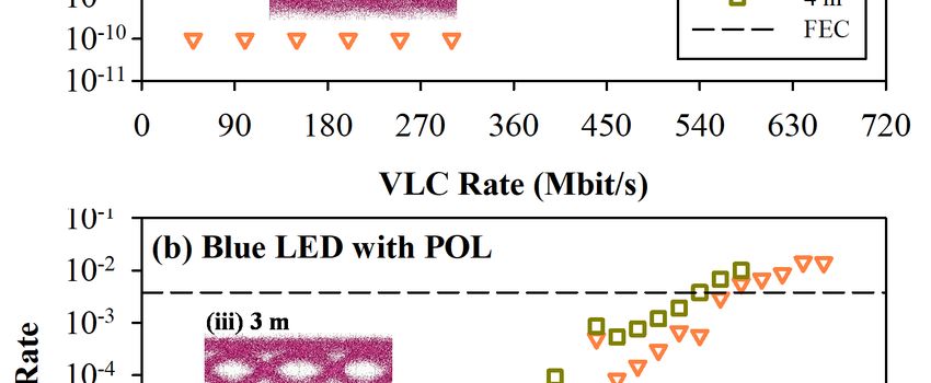
Photonics 2021, 8, x FOR PEER REVIEW                                                                                                                       3 of 12

Photonics 2021, 8, 210                   In our demonstration, to achieve a higher modulation capacity of LED-based3 of                                       VLC12
                                  traffic systems, the G- and B-LEDs with orthogonal polarization are applied at the VLC-
                                  Tx, as illustrated in Figure 1a. Here, the G- and B-LEDs are utilized simultaneously serv-
                                  ing
                                 as    as the wireless
                                    illustrated              VLC
                                                     in Figure    1a.signal.
                                                                       Here, To thedeliver
                                                                                      G- andtwo B-LEDsvarious     VLC modulations
                                                                                                            are utilized      simultaneouslyon theserving
                                                                                                                                                       G- andas   B-
                                  LEDs,     respectively,      two    bias-tees     (BTs)   are   used    to connect
                                 the wireless VLC signal. To deliver two various VLC modulations on the G- and B-LEDs, re-the   individual     LED     and    VLC
                                  modulation
                                 spectively,     two format,
                                                       bias-teeswhen
                                                                   (BTs) theareproper
                                                                                 used tobias      currents
                                                                                             connect           (Ibias) are applied
                                                                                                        the individual        LED andsimultaneously.
                                                                                                                                           VLC modulation         In
                                  addition,      two   optical   polarizers       (POLs,     400700      nm)   are   placed
                                 format, when the proper bias currents (Ibias ) are applied simultaneously. In addition, two     in  front  of  the    G-  and    B-
                                  LEDs to
                                 optical       produce (POLs,
                                           polarizers      orthogonal
                                                                    400−x-   700andnm)y-polarization
                                                                                          are placed instatus
                                                                                                            front of andtheavoid
                                                                                                                             G- and theB-LEDs
                                                                                                                                         interference       of two
                                                                                                                                                   to produce
                                  VLC     signals,    respectively,       as  shown       in  Figure    1a.  Through
                                 orthogonal x- and y-polarization status and avoid the interference of two VLC signals,     a  length    of  optical     wireless
                                  transmission,
                                 respectively,      astwo
                                                       shown wireless
                                                                 in Figuregreen 1a.and     blue VLC
                                                                                     Through             signals
                                                                                                  a length           (VLC(Green)
                                                                                                               of optical           andtransmission,
                                                                                                                             wireless     VLC(Blue)) with       or-
                                                                                                                                                              two
                                  thogonal      polarization     can   be   received      by  the  two   400   MHz      avalanche
                                 wireless green and blue VLC signals (VLC(Green) and VLC(Blue) ) with orthogonal polariza-             photodiodes        (APDs)
                                  at the
                                 tion  can VLC-Rx      side, respectively.
                                              be received      by the two 400     To MHz
                                                                                       enhance      two detected
                                                                                               avalanche                VLC power
                                                                                                               photodiodes         (APDs)andatcorresponding
                                                                                                                                                 the VLC-Rx
                                  VLCrespectively.
                                 side,   signals, the two       focusingtwo
                                                            To enhance         lenses    and POLs
                                                                                     detected     VLCare     also exploited
                                                                                                          power                    for VLC demodulation,
                                                                                                                    and corresponding           VLC signals,
                                  respectively.
                                 the  two focusing    To lenses
                                                          improve  andthe POLsdetected
                                                                                    are alsopower      sensitivity
                                                                                                exploited     for VLC   of demodulation,
                                                                                                                           the VLC signal,respectively.
                                                                                                                                                   the APD is
                                  applied
                                 To  improve  forthesignal  demodulation.
                                                       detected                     Commonly,
                                                                    power sensitivity          of thetheVLCindoor
                                                                                                               signal,illuminance
                                                                                                                         the APD isisapplied
                                                                                                                                           between    for300   and
                                                                                                                                                           signal
                                  750  lux,   sometimes       the  illuminance         will  be  lower.    So,  to  detect
                                 demodulation. Commonly, the indoor illuminance is between 300 and 750 lux, sometimes        and    decode    the   VLC     signal
                                  effectively
                                 the  illuminance under    a longer
                                                        will   be lower.wireless
                                                                              So, tolength
                                                                                        detectatanda lower
                                                                                                        decodeor extra-low
                                                                                                                   the VLC signalilluminance      indoors,
                                                                                                                                          effectively     under the
                                 aAPD-PD        can be applied
                                   longer wireless        length at  in aan  LED or
                                                                           lower     VLC     system illuminance
                                                                                         extra-low     as an alternative.        Although
                                                                                                                          indoors,             APD iscan
                                                                                                                                       the APD-PD          expen-
                                                                                                                                                                be
                                  sive, it is
                                 applied     inanother
                                                 an LED option
                                                            VLC systemin theas  VLC     system. As aAlthough
                                                                                   an alternative.         result, the APD proposed      G anditB-LED
                                                                                                                               is expensive,                  VLC
                                                                                                                                                     is another
                                  transmission
                                 option    in the VLC system    could
                                                           system.     Asdouble
                                                                            a result,thethetraffic
                                                                                             proposedrate G byand
                                                                                                                utilizing
                                                                                                                     B-LEDdual-polarized
                                                                                                                               VLC transmission     VLC      chan-
                                                                                                                                                         system
                                  nels. However,
                                 could    double thethe       tworate
                                                          traffic   POLs  by at   the VLC-Rx
                                                                               utilizing             must match
                                                                                            dual-polarized         VLC thechannels.
                                                                                                                            x- and y-polarization
                                                                                                                                         However, thedirec-   two
                                  tions at
                                 POLs     of the
                                              the VLC-Rx
                                                   VLC(Green)must
                                                                and match
                                                                       VLC(Blue) thesignals.    Commonly, thedirections
                                                                                       x- and y-polarization            offset of x- of and   y-polarizations
                                                                                                                                        the VLC     (Green) and
                                 VLC
                                  of POL
                                       (Blue)  signals.   Commonly,         the   offset   of x-  and   y-polarizations
                                             x and POLy would result in different insertion losses when the                    of  POL    and   POL
                                                                                                                                        x VLC-Rxy module  would
                                 result
                                  movesinarbitrarily.
                                              different insertion
                                                             In previouslossesstudies
                                                                                  when the      VLC-Rx
                                                                                            [17–20],        module
                                                                                                        there    was no  moves     arbitrarily.
                                                                                                                             mention      of VLC  In previous
                                                                                                                                                       problems
                                 studies
                                  caused [17–20],       thereoffset
                                             by different       was no      mention
                                                                         angles.          of VLC in
                                                                                     Therefore,      problems       causedVLC-Rx
                                                                                                         the proposed          by different     offsettoangles.
                                                                                                                                          module,           detect
                                 Therefore,      in the proposed
                                  the two orthogonal                   VLC-Rxfrom
                                                               VLC signals          module,      to detectcompletely,
                                                                                           the VLC-Tx         the two orthogonal          VLC signals
                                                                                                                                two rotatable                from
                                                                                                                                                   dual-polar-
                                 the
                                  izedVLC-Tx
                                         POLs can  completely,     two rotatable
                                                        be controlled                   dual-polarized
                                                                             automatically        based onPOLs         can be controlled
                                                                                                                the maximum           received automatically
                                                                                                                                                  illuminance
                                 based    on the maximum
                                  for decoding        VLC data.received
                                                                    Moreover,   illuminance
                                                                                      to examine  for the
                                                                                                      decoding
                                                                                                            bit errorVLC    data.
                                                                                                                         rate       Moreover,
                                                                                                                                (BER)   performanceto examine
                                                                                                                                                            of the
                                 the  bit   error    rate (BER)     performance          of  the  proposed
                                  proposed LED VLC system, a BER tester is applied for signal measurement.       LED     VLC      system,    a BER      tester is
                                 applied for signal measurement.

                                 Figure 1. (a) Proposed dual-polarized G- and B-LED VLC transmission system. (b) Observed output
                                 spectra of G- and B-LEDs, when the bias currents are both operated at 10 mA.
Analysis and Investigation of Dual-Polarized Color LED Based Visible Light Communication System
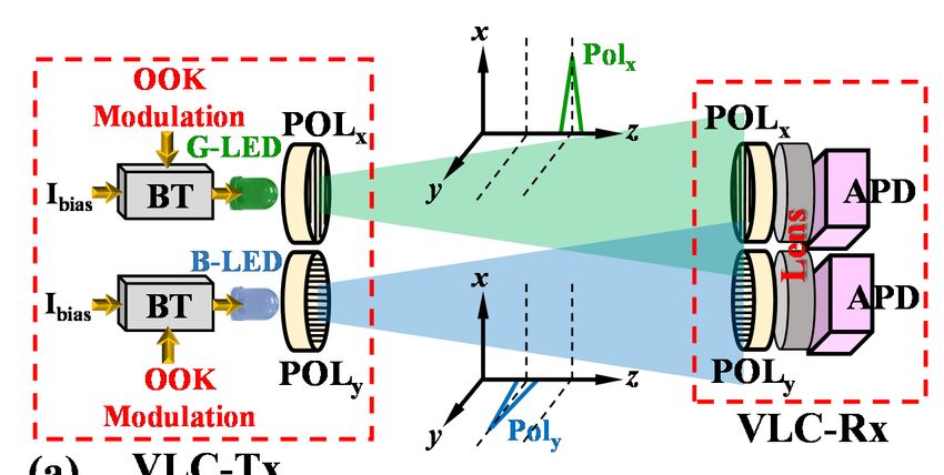
Photonics 2021, 8, 210                                                                                            4 of 12

                         3. Result and Discussion
                               In the experiment, the bias currents of the G- and B-LEDs are both operated at 10 mA.
                         The measured output spectra of the G- and B-LEDs are also shown in Figure 1b. We
                         observed that the central wavelengths of G- and B-LEDs are 457 and 521 nm, respectively.
                         To reach a broader modulation bandwidth of LED, an analog front end (AFE) circuit with
                         pre-equalization was also designed to carry various on-off keying (OOK) modulation
                         signals for delivering VLC traffic at the VLC-Tx [6,8]. In addition, to enhance the detected
                         VLC illuminance, two focusing lenses with 5 cm diameter were also in front of the two
                         APDs, as exhibited in Figure 1a. Due to the smaller Ibias on each LED, the demonstrated
                         LED VLC system also can achieve better energy efficiency.
                               In the demonstration, Figure 2a is the effective bandwidth measured by G-LED and
                         B-LED itself by using the 400 MHz bandwidth APD, respectively. Here, the corresponding
                         detected bandwidths of G- and B-LEDs are nearly 415 and 380 MHz within a 10 dB
                         bandwidth range, respectively. This is due to the limitation of the original 400 MHz APD.
                         According to the achieved results of Figure 2a, the modulation rate of the G- and B-LEDs
                         should be able to reach 400 Mbit/s initially. The valuable bandwidth of the G-LED is better
                         than that of the B-LED in the observation. Furthermore, the original illuminances of the
                         G- and B-LEDs are also detected under various VLC transmission lengths before entering
                         the POL or color filter, respectively, as schemed in Figure 2b. The detected illuminances
                         of the G- and B-LEDs are between 7 and 136.1 lux and 39.1 and 255.1 lux, respectively,
                         under the free space connection lengths of 1 to 4 m. First, we executed the bit error
                         rate (BER) performances of WDM G- and B-LEDs through 3 and 4 m VLC connections,
                         respectively, when the POLs are not used and the corresponding color filters are applied
                         in the measurement. Here, the greatest OOK modulation rates of G- and B-LEDs was
                         670 and 580 Mbit/s and 600 and 560 Mbit/s at the forward error correction (FEC) limit
                         (BER ≤ 3.8 × 10⁻³ ) through 3 and 4 m VLC link lengths, respectively, when the pre- and
                         post-equalizations are applied on the Tx- and Rx-VLC sides, as shown in Figure 3a,b. We
                         only used 400 MHz APD with an equalization circuit in the presented VLC system to
                         decode 670 Mbit/s OOK signal. These have two benefits, the first one can reduce costs,
                         and the other one can increase the decoding bandwidth in the demonstration.
                               Second, we performed the proposed dual-polarized VLC system through different
                         free-space transmission lengths. Hence, the corresponding illuminances of the G- and
                         B-LEDs after passing through two POLs with parallel polarization before launching into the
                         focusing lens were measured first. Figure 4 displays the detected illuminance of the G- and
                         B-LEDs after a free-space link length of 1 to 4 m, respectively. The achievable illuminances of
                         the G- and B-LEDs are obtained between 0.5 and 22.7 lux and 2.3 and 31.9 lux, respectively,
                         as seen in Figure 4. Here, to establish the long indoor VLC transmission length, we selected
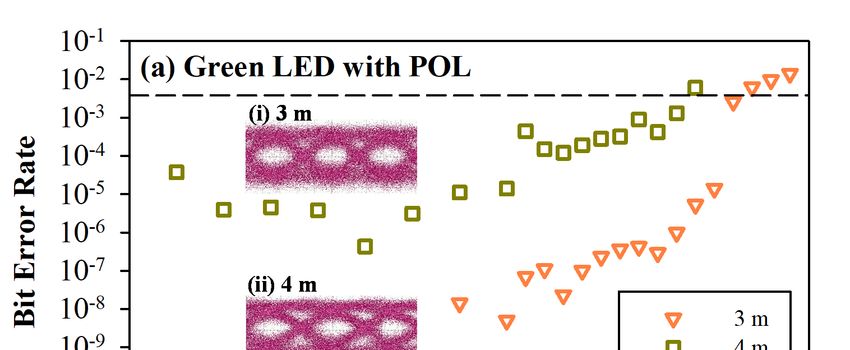
                         3 and 4 m links for the VLC(Green) and VLC(Blue) connections, respectively. Figure 5a,b
                         exhibit the obtained bit error rate (BER) performances of the VLC(Green) and VLC(Blue)
                         traffics versus various OOK modulation rates after an optical wireless transmission length
                         of 3 and 4 m, respectively. In the measurement, the largest VLC(Green) data rates of 640
                         and 580 Mbps were achieved below the forward error correction (FEC) threshold (BER of
                         3.8 × 10⁻³ ), respectively, through a wireless link of 3 and 4 m, when the corresponding
                         illuminances were 2.4 and 0.5 lux (before entering the lens), as shown in Figure 5a. The
                         insets of (i) and (ii) of Figure 5a are the corresponding eye diagrams at the 640 and 580 Mbps,
                         respectively. Identically, the OOK VLC(Blue) traffics could also reach 560 and 540 Mbps
                         after 3 and 4 m free-space transmissions to satisfy the FEC target under the corresponding
                         illuminances of 5.4 and 2.3 lux, respectively, as illustrated Figure 5b. The insets of (iii) and
                         (iv) of Figure 5b are the measured eye diagrams at the 560 and 540 Mbps VLC(Blue) rates,
                         respectively. As displayed in Figure 5a,b, the modulation rate of the G-LED seems better
                         than that of B-LED due to the characteristics of the component itself. According to the
                         presented dual-polarized G- and B-LED VLC system, the largest VLC traffics of 1200 Gbps
                         (640(Green) + 560(Blue) Mbps) and 1120 Mbps (580(Green) + 540(Blue) Mbps) were obtained
Photonics 2021, 8, x FOR PEER REVIEW                                                                                              5 of 12

Photonics 2021, 8, 210                                                                                                        5 of 12
                                    seems better than that of B-LED due to the characteristics of the component itself. Accord-
                                    ing to the presented dual-polarized G- and B-LED VLC system, the largest VLC traffics of
                                    1200 Gbps (640(Green) + 560(Blue) Mbps) and 1120 Mbps (580(Green) + 540(Blue) Mbps) were ob-
                                    tained under 3 and 4 m free-space link lengths, respectively, when the equalization
                                   under 3 and 4 m free-space link lengths, respectively, when the equalization method was
                                    method was applied on the AFE side under the very low illuminance for decoding data.
                                   applied on the AFE side under the very low illuminance for decoding data.

                                                                  5

                                      Normalized Response [dB]
                                                                                                                               (a)
                                                                  -5

                                                                 -15

                                                                 -25
                                                                                    B-LED
                                                                 -35                G-LED

                                                                 -45
                                                                       0       100          200     300     400         500      600
                                                                                             Frequency [MHz]
                                                                 300
                                                                                                                              (b)
                                                                 250
                                       Illuminance [lux]

                                                                 200                                                     G-LED
                                                                                                                         B-LED
                                                                 150

                                                                 100

                                                                  50
                                                                           without POL
                                                                   0
                                                                       0.5    1.0    1.5      2.0   2.5   3.0     3.5    4.0     4.5
                                                                                             VLC Length [m]
                                     Figure2.2.(a)
                                   Figure       (a)Measured
                                                   Measured achievable
                                                              achievable bandwidths
                                                                         bandwidths of
                                                                                    ofthe
                                                                                       theG
                                                                                          G−and
                                                                                             andBLEDs.
                                                                                                 B−LEDs.(b)(b)
                                                                                                            Detected corresponding
                                                                                                               Detected corresponding
                                     illuminances of the G and BLEDs without using POL versus various VLC lengths before launch-
                                   illuminances of the G− and B−LEDs without using POL versus various VLC lengths before launching
                                     ing into the focusing lens.
                                   into the focusing lens.

                                         In the demonstration, we could not only apply two various color LEDs in the presented
                                   dual-polarized VLC system but also we could utilize two same color LEDs. We could also
                                   utilize a pair of polarization-multiplexing G-LEDs (or B-LEDs) at the VLC-Tx for delivering
                                   wireless VLC traffics. Therefore, the maximum dual-polarized G-LED VLC(Green) and
                                   B-LED VLC(Blue) rates of 2 × 640 and 2 × 580 Mbps; and 2 × 560 and 2 × 540 Mbps were
                                   achieved after 3 and 4 m optical wireless connections, respectively. This means that we
                                   can arbitrarily use the combination of two LEDs for dual-polarized VLC transmission.
                                   Moreover, the observed BER measurements of dual-polarized VLC(Green) and VLC(Blue)
                                   under different modulated rates were similar to Figure 5a,b, therefore we do not exhibit
                                   the BER measurements here. As mentioned above, this means that we can arbitrarily use
                                   the combination of two LEDs for dual-polarized VLC transmission.
Photonics 2021, 8, 210                                                                                                        6 of 12

                                          According to the results of Figures 4 and 5, the achieved largest VLC rate depends on
                                    the detected illuminance. The obtained VLC power would affect the signal performance.
                                    As the VLC transmission length increases, the available signal capacity will be relatively
                                    smaller, due to the weaker corresponding detected power. Therefore, a >1 Gbit/s OOK rate
                                    through a 4 m wireless connection can be achieved in the proposed dual-polarized LED
                                    VLC system.
                                          However, while the polarization of two orthogonal POLs is offset at the VLC-Rx, the
                                    obtained VLC signal would be influenced and interfered with due to two mixed VLC
                                    traffics. To avoid this problem, the two POLs can be controlled for rotation automatically
                                    based on the maximum detected illuminance. In the investigation, we demonstrate and
                                    discuss the VLC performance of the G- and B-LEDs under the different offset angles. For
                                    example, according to the measured results of Figure 5a, we select the 620 and 440 Mbps
                                    OOK modulations under the free-space link of 3 and 4 m for VLC(Green) BER demonstration
                                    when the various rotation angle of POL is changed gradually. Figure 6a,b present the
                                    observed BER performances of G-LED versus the various rotation angles of 0◦ to 90◦ with
                                    the corresponding illuminances of 0 to 2.4 lux and 0 to 0.5 lux, respectively. To meet with
                                    the VLC(Green) traffic below the FEC threshold, the offset angles must be small 6than
  Photonics 2021, 8, x FOR PEER REVIEW                                                                                    of 12 50
                                                                                                                                   ◦
                                            ◦
                                    and 45 , respectively, after 3 (illuminance = 0.9 lux) and 4 m (illuminance = 0.3 lux) optical
                                    wireless transmissions, as illustrated in Figure 6a,b.

                                                   10-1
                                                   10-2        (a) G-LED
                                                   10-3
                                  Bit Error Rate

                                                   10-4
                                                   10-5
                                                   10-6
                                                   10-7
                                                                                                           3m
                                                   10-8                                                    4m
                                                   10-9                                                    FEC

                                                   10-10
                                                           0     100   200    300   400   500    600     700     800
                                                                             VLC Rate [Mbit/s]
                                                   10-1
                                                   10-2        (b) B-LED
                                                   10-3
                                  Bit Error Rate

                                                   10-4
                                                   10-5
                                                   10-6
                                                   10-7
                                                                                                           3m
                                                   10-8                                                    4m
                                                   10-9                                                    FEC

                                                   10-10
                                                           0     100   200    300   400   500    600     700     800
                                                                             VLC Rate [Mbit/s]
                                Figure 3.
                                Figure   3. Different
                                            Different measured
                                                      measuredVLC
                                                               VLCrates
                                                                    ratesofof(a)
                                                                              (a)G
                                                                                  G−and
                                                                                     and(b)(b)
                                                                                             BLEDs versus
                                                                                               B−LEDs      the the
                                                                                                       versus   corresponding BERBER
                                                                                                                   corresponding
                                after 3 and 4 m freespace transmissions under WDM VLC connection, respectively.
                                after 3 and 4 m free−space transmissions under WDM VLC connection, respectively.

                                                   35
                                                   30                                            G-LED
                                                                                                 B-LED
                                  [lux]

                                                   25
10-10
                                                                     0     100        200     300    400   500   600      700   800
                                                                                            VLC Rate [Mbit/s]
Photonics 2021, 8, 210                                                                                                                          7 of 12
                                     Figure 3. Different measured VLC rates of (a) G and (b) BLEDs versus the corresponding BER
                                     after 3 and 4 m freespace transmissions under WDM VLC connection, respectively.

                                                          35
                                                          30                                                     G-LED
                                                                                                                 B-LED

                                      Illuminance [lux]
                                                          25
                                                          20
                                                          15
                                                          10
                                                           5
                                                                     with POL
                                                           0
                                                               0.5       1.0    1.5     2.0    2.5   3.0   3.5   4.0     4.5
                                                                                       VLC Length [m]
     Photonics 2021, 8, x FOR PEER REVIEW                                                                                             7 of 12
                                     Figure 4. Measured corresponding
                                                         corresponding illuminances
                                                                        illuminances of
                                                                                     ofthe
                                                                                        theGG− and    −LEDs after passing through two
                                                                                                 and BBLEDs
                                     POLs with parallel polarization before launching into the focusing
                                                                                               focusing lens.
                                                                                                        lens.

                                      Figure5.5. Measured
                                     Figure      Measured different
                                                            differentVLC
                                                                      VLCrates
                                                                           ratesof of
                                                                                   (a)(a)
                                                                                       GGand   (b) BLEDs
                                                                                            − and          versusversus
                                                                                                    (b) B−LEDs     the corresponding    BER
                                                                                                                          the corresponding   BER
                                      after33and
                                     after   and 44m
                                                   m free-space
                                                      free-spacetransmissions. Insets
                                                                  transmissions.      are the
                                                                                   Insets are corresponding
                                                                                               the          eye diagrams
                                                                                                   corresponding  eye      at the maximum
                                                                                                                       diagrams    at the maximum
                                      VLC rate below the FEC limit of BER = 3.8  10−3.
                                     VLC rate below the FEC limit of BER = 3.8 × 10⁻³ .
                                           In the demonstration, we could not only apply two various color LEDs in the pre-
                                      sented dual-polarized VLC system but also we could utilize two same color LEDs. We
                                      could also utilize a pair of polarization-multiplexing G-LEDs (or B-LEDs) at the VLC-Tx
                                      for delivering wireless VLC traffics. Therefore, the maximum dual-polarized G-LED
                                      VLC(Green) and B-LED VLC(Blue) rates of 2  640 and 2  580 Mbps; and 2  560 and 2  540
                                      Mbps were achieved after 3 and 4 m optical wireless connections, respectively. This means
OOK modulations under the free-space link of 3 and 4 m for VLC(Green) BER demonstration
                         when the various rotation angle of POL is changed gradually. Figure 6a,b present the ob-
                         served BER performances of G-LED versus the various rotation angles of 0 to 90 with
                         the corresponding illuminances of 0 to 2.4 lux and 0 to 0.5 lux, respectively. To meet with
                         the VLC(Green) traffic below the FEC threshold, the offset angles must be small than 50 and
Photonics 2021, 8, 210                                                                                         8 of 12
                         45, respectively, after 3 (illuminance = 0.9 lux) and 4 m (illuminance = 0.3 lux) optical
                         wireless transmissions, as illustrated in Figure 6a,b.

                                            10-1                                                                    3
                                                       (a) 3m VLC

                                                                                                                          Illuminance [Lux]
                                            10-2

                           Bit Error Rate
                                                                                                                    2

                                            10-3

                                                                                                                    1
                                            10-4

                                            10-5                                                                    0
                                            10-1                                                                    0.6
                                                       (b) 4m VLC                                BER
                                                                                                 illuminance        0.5

                                                                                                                                       Illuminance [Lux]
                                                                                                 FEC
                           Bit Error Rate

                                            10-2                                                                    0.4

                                                                                                                    0.3

                                            10-3                                                                    0.2

                                                                                                                    0.1

                                            10-4                                                                    0.0
                                                   0        15      30     45         60           75          90
                                                                 Rotoaion Angle [degree]
                          Figure 6. VLC(Green) BER measurements of 620 and 440 Mbps after the freespace link of (a) 3 and (b)
                         Figure 6. VLC(Green) BER measurements of 620 and 440 Mbps after the free−space link of (a) 3 and
                          4 m under different corresponding illuminance.
                         (b) 4 m under different corresponding illuminance.

                                Next, to
                              Next,      to understand
                                             understand thethe effect
                                                                effectof
                                                                       ofoffset
                                                                          offsetangle
                                                                                   angleforforthe
                                                                                               theB-LED-based
                                                                                                     B-LED-basedVLC   VLCtraffic,
                                                                                                                            traffic,wewe
                          applied   520    and  500 Mbps     OOK    VLC   signals   for  the  BER    measurements
                         applied 520 and 500 Mbps OOK VLC signals for the BER measurements under various               under    various
                          offsetangles
                         offset  anglesaccording
                                            accordingtotothe
                                                           theobtained
                                                               obtainedresults
                                                                          resultsof ofFigure
                                                                                       Figure5b.5b.Therefore,
                                                                                                     Therefore,Figure
                                                                                                                   Figure7a,b
                                                                                                                          7a,bexhibit
                                                                                                                                 exhibit
                          theobserved
                         the  observedBER    BERpresentations
                                                  presentationsof  ofB-LED
                                                                      B-LEDversus
                                                                               versusthethevarious
                                                                                             variousrotation
                                                                                                         rotationangles
                                                                                                                   anglesofof00toto90
                                                                                                                               ◦      90
                                                                                                                                       ◦
                          underthe
                         under    thecorresponding
                                        correspondingilluminances
                                                          illuminances  ofof  0 to
                                                                           0 to 5.45.4
                                                                                     luxlux
                                                                                          andand
                                                                                               0 to0 2.4
                                                                                                      to 2.4
                                                                                                          lux,lux, respectively.
                                                                                                               respectively.  To fitTo fit
                                                                                                                                     the
                          the VLC          signal below   the  FEC  threshold,    the  offset  angles   must    be
                         VLC(Blue) signal below the FEC threshold, the offset angles must be small than 45 and 35◦
                                    (Blue)                                                                         small than◦  45  and
                         after 3 (illuminance = 1.6 lux) and 4 m (illuminance = 2.9 lux) free-space connections, as
                         demonstrated in Figure 7a,b.
                              The influence of the offset angle on the maximum VLC modulation rate is also a critical
                         issue. As mentioned above, the maximum VLC modulation rates are 580 and 540 Mbps
                         for the G- and B-LED VLC transmissions under a 4 m free-space link, respectively. In the
                         measurement, when the offset angle of POL is increased gradually from 0◦ to 50◦ , the
                         corresponding largest modulation rates of G- and B-LED VLC traffics can be obtained
                         within the FEC target, as shown in Figure 8. In this measurement, the maximum G-LED
                         VLC of 500, 440 and 300 Mbps are achieved under the offset angle of 30◦ , 40◦ and 50◦ ,
                         respectively. The 500, 450 and 400 Mbps traffics of B-LED VLC link are also observed under
                         the offset angle of 30◦ , 40◦ and 50◦ , respectively. This is because the illuminance of the
                         G-LED itself is smaller than that of the B-LED. Once the angle is over 50◦ , the VLC(Green)
                         and VLC(Blue) traffics would be not obtained due to the larger insertion loss. Therefore, the
                         results show that the corresponding illuminances of the G- and B-LEDs must be greater
                         than 0.2 and 1 lux to obtain optimal VLC performance through a 4 m free-space connection.
                         As exhibited in Figure 8, we can obtain the same data rate of 500 Mbps for the VLC(Green)
                         and VLC(Blue) connections, when the offset angle is rotated at 30◦ . In addition, with a
Photonics 2021, 8, x FOR PEER REVIEW                                                                                                               9 of 12
Photonics 2021, 8, 210                                                                                                                             9 of 12

                                  35 after 3 (illuminance = 1.6 lux) and 4 m (illuminance = 2.9 lux) free-space connections,
                                 gradual  increase ininthe
                                  as demonstrated          offset7a,b.
                                                        Figure    angle, the measured modulation signal of the B-LED would
                                 also be larger than that of the G-LED.

                                                     10-1                                                                              7
                                                                (a) 3m VLC
                                                                                                                                       6

                                                                                                                                            Illuminance [Lux]
                                   Bit Error Rate    10-2                                                                              5
                                                                                                                                       4
                                                     10-3
                                                                                                                                       3

                                                     10-4                                                                              2
                                                                                                                                       1
                                                     10-5                                                                              0
                                                     10-1                                                                              3
                                                                (b) 4m VLC                                         BER
                                                                                                                   illuminance

                                                                                                                                            Illuminance [Lux]
                                                                                                                   FEC
                                    Bit Error Rate

                                                                                                                                       2

                                                     10-2

                                                                                                                                       1

                                                     10-3                                                                              0
                                                            0        15      30          45            60           75            90
                                                                          Rotoaion Angle [degree]
                                  Figure7.7.VLC
                                            VLC(Blus) BER measurements of 620 and 440 Mbps after the freespace link of (a) 3 and (b)
                                 Figure         (Blus) BER measurements of 620 and 440 Mbps after the free−space link of (a) 3 and
                                  4 m under different corresponding illuminance.
                                 (b) 4 m under different corresponding illuminance.

                                        InThe
                                            theinfluence    of the offset
                                                 demonstration,      owing  angle  on blended
                                                                              to two   the maximum       VLC modulation
                                                                                                  orthogonal    VLC signals,rate  the is alsotraffic
                                                                                                                                       VLC     a crit-
                                   ical can
                                 also    issue.   As mentioned
                                             provide                 above, the
                                                        security operation          maximum
                                                                               in the             VLC based
                                                                                      physical layer     modulation      ratesinterference
                                                                                                                on channel       are 580 and      540
                                                                                                                                              if the
                                   Mbps for the
                                 polarization      ofG-
                                                      theand
                                                           POLsB-LED    VLC
                                                                  are not      transmissions
                                                                            matching.    In our under
                                                                                                 previousa 4 study
                                                                                                             m free-space
                                                                                                                     [23], thelink,
                                                                                                                                two respectively.
                                                                                                                                      mixed VLC
                                   In the measurement,
                                 signals    with similar power when    the offset
                                                                    would     causeangle
                                                                                     very of   POL data
                                                                                            serious  is increased    gradually
                                                                                                           interference.           from the
                                                                                                                            To decode     0 to  50,
                                                                                                                                              dual-
                                   the  corresponding       largest  modulation      rates  of G-  and  B-LED    VLC    traffics
                                 polarized VLC signals, two orthogonal POLs with precise direction controls are required at       can  be obtained
                                   within
                                 the  VLC-Rx the FEC
                                                  side, target,
                                                         when theas client
                                                                    shownisin  in Figure   8. arbitrary
                                                                                  a state of  In this measurement,
                                                                                                         movement. The    thecontrol
                                                                                                                               maximum of theG-LED
                                                                                                                                               POL
                                 isVLC    of 500, 440
                                     dependent      on theandmaximum
                                                                300 Mbpsdetected
                                                                             are achieved      under the
                                                                                       illuminance          offset angle
                                                                                                       for proper            of 30,
                                                                                                                     rotation.    The40   and 50,
                                                                                                                                        schematic
                                   respectively.
                                 diagram      of theThe   500, 450
                                                       control       and is
                                                                 design    400  Mbps traffics
                                                                             illustrated         of B-LED
                                                                                            in Figure   9 forVLC
                                                                                                              proof link
                                                                                                                       of are  also observed
                                                                                                                           concept.    Hence, the un-
                                   der the offset angle
                                 corresponding               of 30, can
                                                      VLC signal     40 be
                                                                          anddetected
                                                                                50, respectively.   This isrotation.
                                                                                          through proper      because Additionally,
                                                                                                                          the illuminance      of the
                                                                                                                                           if there
                                   G-LED
                                 are  manyitself     is smaller
                                               clients  with only than
                                                                    onethat    of the B-LED.
                                                                         Rx detector             Onceroom
                                                                                         in the same    the angle    is over 50,
                                                                                                               for receiving         the VLC(Green)
                                                                                                                                a dual-polarized
                                 VLC     signal,  the   polarization    of the  POL   for  each  client  can  be  adjusted
                                   and VLC(Blue) traffics would be not obtained due to the larger insertion loss. Therefore,  properly    to sharethe
                                 and    adapt
                                   results   showthethat
                                                      totalthe
                                                             capacity.   Therefore,
                                                                corresponding          the proposed
                                                                                   illuminances          dual-polarized
                                                                                                    of the  G- and B-LEDs     LED   VLC
                                                                                                                                 must    besystem
                                                                                                                                             greater
                                 can
                                   thannot0.2only
                                               anddouble
                                                    1 lux to the data rate
                                                               obtain        but can
                                                                        optimal    VLC also  provide a security
                                                                                          performance     throughfunction       accordingconnec-
                                                                                                                      a 4 m free-space       to the
                                 polarization-based
                                   tion. As exhibitedfilter. in Figure 8, we can obtain the same data rate of 500 Mbps for the
                                   VLC(Green) and VLC(Blue) connections, when the offset angle is rotated at 30. In addition,
                                   with a gradual increase in the offset angle, the measured modulation signal of the B-LED
                                   would also be larger than that of the G-LED.
0
                     250       300                               350                400   450             500                  550           600
 Photonics2021,
Photonics  2021,8,8,210
                     x FOR PEER REVIEW                                                                                                                           1010ofof1212
                                                                       VLC Rate [Mbit/s]
       Figure 8. Obtained corresponding modulation rates of VLC(Green) and VLC(Green) within the FEC level
       under the different rotation angles from 0 to 50.
                                                               60

                                    Rotation Angle [degree]
             In the demonstration, 50 owing to two blended orthogonal VLC signals, the VLC traffic
       also can provide security operation in the physical layer based on channel interference if
       the polarization of the POLs40 are not matching. In our previous study [23], the two mixed
       VLC signals with similar power would cause very serious data interference. To decode
       the dual-polarized VLC 30   signals, two orthogonal POLs with precise direction controls are
       required at the VLC-Rx side,20 when the client is in a state of arbitrary movement. The con-
       trol of the POL is dependent on the maximum   Green         detected illuminance for proper rotation.
       The schematic diagram of    10the control Bluedesign is illustrated in Figure 9 for proof of concept.
       Hence, the corresponding VLC signal can be detected through proper rotation. Addition-
                                     0 with only one Rx detector in the same room for receiving a
       ally, if there are many clients
       dual-polarized VLC signal,250            300
                                        the polarization   350 of the400POL450   for each  500client550  can be600  adjusted
       properly to share and adapt the total capacity.         VLC  Therefore,
                                                                       Rate [Mbit/s]  the proposed dual-polarized
       LED VLC system can not only double the data rate but can also provide a security function
                             Figure8.8.Obtained
                            Figure     Obtained corresponding
                                                 corresponding modulation
                                                                modulation rates
                                                                              rates of
                                                                                    ofVLC
                                                                                        VLC(Green)
                                                                                            (Green)and VLC
                                                                                                     and   (Green) within
                                                                                                         VLC              the FEC
                                                                                                              (Green) within       level
                                                                                                                              the FEC
       according to the polarization-based         filter.angles from 0 to 50.
                             under the different rotation                   ◦       ◦
                                  level under the different rotation angles from 0 to 50 .

                                     In the demonstration, owing to two blended orthogonal VLC signals, the VLC traffic
                 POLx         POL y
                                                   POL         POL                        POL
                                also can provide security xoperation iny the physical layer          POLy interference if
                                                                                                x on channel
                                                                                            based
                            the polarization of the POLs are not matching. In our previous study [23], the two mixed
                            VLC signals with similar power would cause very serious data interference. To decode
                            the dual-polarized VLC signals, two orthogonal POLs with precise direction controls are
                                                                                                                 illuminance
                                                                     illuminance

                            required at the VLC-Rx side, when the client is in a state of arbitrary movement. The con-
                            trol of the POL is dependent on the maximum detected illuminance for proper rotation.
                            The schematic diagram of the control design is illustrated in Figure 9 for proof of concept.
                            Hence, the corresponding VLC signal can be detected through proper rotation. Addition-
                            ally, if there are many clients with only one Rx detector in the same room for receiving a
                            dual-polarized VLC signal, the polarization of the POL for each client can be adjusted
                 VLC Signal properly to share andVLC adaptSignal
                                                                                          VLC Signal
                                                             the total capacity. Therefore, the proposed dual-polarized
          (a)   Original Power
                            LED VLC system   (b)canPOL    Offset
                                                    not only double the data rate(c)  Proper
                                                                                  but can        Rotation
                                                                                          also provide a security function
                            according to the polarization-based filter.
       Figure 9. Schematic
              Figure        diagram
                     9. Schematic      of the
                                  diagram      POL’s
                                           of the POL’srotation   control
                                                        rotation control forfor decoding
                                                                             decoding     dual-polarized
                                                                                      dual-polarized        VLC traffics.
                                                                                                     VLC traffics.
                                                                POLx               POLy                 POLx    POLy                               POLx   POLy
       4. Conclusions             4. Conclusions
                                                              We proposed and investigated 2 × 2 PDM G- and B-LED VLC transmission systems
           We proposed andwith investigated    2  2 PDM
                               orthogonal-polarization        G- and
                                                         to double the B-LED    VLC
                                                                       data traffic.    transmission
                                                                                     Here, to obtain the systems
                                                                                                         dual-polarized
                                                                                                                                     illuminance
                                                                                          illuminance

       with orthogonal-polarization
                          VLC signals,tothe
                                          double   the dataPOLs
                                            two orthogonal    traffic. Here,
                                                                    at the     to obtain
                                                                           VLC-Rx           the dual-polarized
                                                                                     side could  be controlled for rota-
       VLC signals, the two  orthogonal
                          tion            POLs
                               automatically      at thethe
                                              to match    VLC-Rx     side could
                                                             dual-polarized  VLC be    controlled
                                                                                   signals  from thefor  rotation
                                                                                                      VLC-Tx  site. The
                                  presented dual-polarized VLC system could accomplish the total modulation rate of 1200
                                  and 1120 Mbps (VLC(Green+Blue) ) passing after 3 and 4 m free-space transmission lengths,
                                  respectively,
                                             VLCwhen
                                                  Signalthe corresponding VLC  illuminances
                                                                                     Signal of the G- and B-LEDs          were 2.4 and
                                                                                                                  VLC Signal
                                  0.5 lux and 5.4 and 2.3 lux. To produce the more flexible proposed dual-polarized VLC
                                     (a) Original Power                 (b) POL Offset                     (c) Proper Rotation
                                  system, we also can employ paired G-LEDs and B-LEDs acting as the optical Tx to deliver
                                  dual-polarized VLC(Green) and VLC(Blue) signals for alternative indoor applications. Hence,
                                   Figure 9. Schematic diagram of the POL’s rotation control for decoding dual-polarized VLC traffics.
                                  the proposed 2 × 2 PDM G- and B-LED VLC system did not need to use a color filter for
                                  decoding signals. In addition, we also executed and analyzed the influence of different
                                   4. Conclusions
                                  polarization offsets at a fixed VLC rate through a wireless link length of 3 and 4 m, respec-
                                  tively.We  proposed
                                          Based         and investigated
                                                 on the observed             2 largest
                                                                   results, the  2 PDMoffset
                                                                                          G- and    B-LED
                                                                                                angle       VLC
                                                                                                       of the twotransmission
                                                                                                                   POLs shouldsystems
                                                                                                                                  be less
                                   with  orthogonal-polarization
                                           ◦                         to double   the data  traffic. Here,
                                  than 50 to maintain the optimal VLC modulation rate below the forward    to obtain theerror
                                                                                                                          dual-polarized
                                                                                                                              correction
                                   VLC signals,
                                  (FEC)           the two orthogonal
                                         level. Furthermore,             POLsmany
                                                               if there were    at theclients
                                                                                       VLC-Rx    side
                                                                                              with     could
                                                                                                     only onebeRxcontrolled
                                                                                                                  detector infor rotation
                                                                                                                               the same
Photonics 2021, 8, 210                                                                                                           11 of 12

                                  room for receiving dual-polarized VLC traffic, the polarization of the POL for each client
                                  could be controlled properly to share and adapt the total capacity. Hence, the proposed
                                  dual-polarized LED VLC system not only doubled the data rate but also provided signal
                                  security according to the PDM method.

                                  Author Contributions: Conceptualization, C.-H.Y.; methodology, S.-K.L.; validation, Y.-C.Y., W.-H.H.
                                  and B.-Y.W.; resources, C.-H.Y. and C.-W.C.; data curation, Y.-C.Y., W.-H.H. and B.-Y.W.; writing—
                                  original draft preparation, C.-H.Y. and Y.-C.Y.; writing—review and editing, C.-H.Y.; supervision,
                                  C.-H.Y. and S.-K.L. All authors have read and agreed to the published version of the manuscript.
                                  Funding: This paper was supported by the Ministry of Science and Technology, Taiwan, under Grant
                                  MOST-109-2221-E-035-071.
                                  Institutional Review Board Statement: Not applicable.
                                  Informed Consent Statement: Not applicable.
                                  Data Availability Statement: Not applicable.
                                  Conflicts of Interest: The authors declare no conflict of interest.

References
1.    Rajagopal, S.; Roberts, R.D.; Lim, S.K. IEEE 802.15.7 visible light communication: Modulation schemes and dimming support.
      IEEE Commun. Mag. 2012, 50, 72–82. [CrossRef]
2.    Chi, N.; Zhou, Y.; Liang, S.; Wang, F.; Li, J.; Wang, Y. Enabling technologies for high-speed visible light communication employing
      CAP modulation. J. Lightwave Technol. 2018, 36, 510–518. [CrossRef]
3.    Lan, H.-Y.; Tseng, I.-C.; Lin, Y.-H.; Lin, G.-R.; Huang, D.-W.; Wu, C.-H. High-Speed integrated micro-LED array for visible light
      communication. Opt. Lett. 2020, 45, 2203–2206. [CrossRef] [PubMed]
4.    Chow, C.-W.; Shiu, R.-J.; Liu, Y.-C.; Liu, Y.; Yeh, C.-H. Non-Flickering 100 m RGB visible light communication transmission based
      on a CMOS image sensor. Opt. Express 2018, 26, 7079–7084. [CrossRef] [PubMed]
5.    Xie, E.; Bain, R.; He, X.; Islim, M.S.; Chen, C.; McKendry, J.J.D.; Gu, E.; Haas, H.; Dawson, M.D. Over 10 Gbps VLC for
      long-distance applications using a GaN-based series-biased micro-LED array. IEEE Photonics Technol. Lett. 2020, 32, 499–502.
      [CrossRef]
6.    Yeh, C.-H.; Chen, H.-Y.; Chow, C.-W.; Liu, Y.-L. Utilization of multi-band OFDM modulation to increase traffic rate of phosphor-
      LED wireless VLC. Opt. Express 2015, 23, 1133–1138. [CrossRef] [PubMed]
7.    Elgala, H.; Mesleh, R.; Haas, H. Indoor optical wireless communication: Potential and state-of-the-art. IEEE Commun. Mag. 2011,
      49, 56–62. [CrossRef]
8.    Yeh, C.-H.; Liu, Y.-F.; Chow, C.-W.; Liu, Y.; Huang, P.-Y.; Tsang, H.-K. Investigation of 4-ASK modulation with digital filtering
      to increase 20 times of direct modulation speed of white-light LED visible light communication system. Opt. Express 2012, 20,
      16218–16223. [CrossRef]
9.    Minh, H.L.; O’Brien, D.; Faulkner, G.; Zeng, L.; Lee, K.; Jung, D.; Oh, Y.J.; Won, E.T. 100-Mb/s NRZ visible light communications
      using a postequalized white LED. IEEE Photonics Technol. Lett. 2009, 21, 1063–1065. [CrossRef]
10.   Wang, L.; Wang, X.; Kang, J.; Yue, C.P. A 75-Mb/s RGB PAM-4 visible light communication transceiver system with pre- and
      post-equalization. J. Lightwave Technol. 2020, 35, 1381–1390.
11.   Han, D.; Lee, K. High speed parallel transmission visible light communication method with multiple LED matrix image processing
      technique. In Proceedings of the 11th International Conference on Ubiquitous and Future Networks ICUFN, Zagreb, Croatia, 2–5
      July 2019; pp. 576–580.
12.   Tokgoz, S.C.; Anous, N.; Yarkan, S.; Khalil, D.; Qaraqe, K.A. Performance improvement of white LED-based VLC systems using
      blue and flattening filters. In Proceedings of the International Conference on Advanced Communication Technologies and
      Networking (CommNet), Rabat, Morocco, 12–14 April 2019; pp. 1–6.
13.   Hsu, C.-W.; Chow, C.-W.; Lu, I.-C.; Liu, Y.-L.; Yeh, C.-H.; Liu, Y. High speed imaging 3 × 3 MIMO phosphor white-light LED
      based visible light communication system. IEEE Photonics J. 2016, 8, 7907406. [CrossRef]
14.   Wei, L.; Zhang, H.; Song, J. Experimental demonstration of a cubic-receiver-based MIMO visible light communication system.
      IEEE Photonics J. 2019, 9, 7900107. [CrossRef]
15.   Wang, Y.; Tao, L.; Huang, X.; Shi, J.; Chi, N. 8-Gb/s RGBY LED-based WDM VLC system employing high-order CAP modulation
      and hybrid post equalizer. IEEE Photonics J. 2015, 7, 7904507.
16.   Luo, P.; Zhang, M.; Ghassemlooy, Z.; Minh, H.L.; Tsai, H.-M.; Tang, X.; Png, L.C.; Han, D. Experimental demonstration of RGB
      LED-based optical camera communications. IEEE Photonics J. 2015, 7, 7904212. [CrossRef]
17.   Yeh, C.-H.; Weng, J.-H.; Chow, C.-W.; Luo, C.-M.; Xie, Y.-R.; Chen, C.-J.; Wu, M.-C. 1.7 to 2.3 Gbps OOK LED VLC transmission
      based on 4 × 4 color-polarization-multiplexing at extremely low illumination. IEEE Photonics J. 2019, 11, 7904206. [CrossRef]
Photonics 2021, 8, 210                                                                                                         12 of 12

18.   Wang, Y.; Yang, C.; Wang, Y.; Chi, N. Gigabit polarization division multiplexing in visible light communication. Opt. Lett. 2014,
      39, 1823–1826. [CrossRef] [PubMed]
19.   Hsu, C.W.; Yeh, C.H.; Chow, C.W. Using adaptive equalization and polarization-multiplexing technology for Gigabit-per-second
      phosphor-LED wireless visible light communication. Opt. Laser Technol. 2018, 104, 206–209. [CrossRef]
20.   Lu, I.-C.; Lai, C.-H.; Yeh, C.-H.; Chen, J. 6.36 Gbit/s RGB LED-based WDM MIMO visible light communication system employing
      OFDM modulation. In Proceedings of the Optical Fiber Communications Conference and Exhibition (OFC), Los Angeles, CA,
      USA, 19–23 March 2017. paper W2A.39.
21.   Yang, Y.; Chen, C.; Zhang, W.; Deng, X.; Du, P.; Yang, H.; Zhong, W.-D.; Chen, L. Secure and private NOMA VLC using OFDM
      with two-level chaotic encryption. Opt. Express 2018, 26, 34031–34042. [CrossRef] [PubMed]
22.   Husagic-Selman, A.; Al-Khateeb, W.; Saharudin, S. Feasibility of QKD over FSO link. In Proceedings of the International
      Conference on Computer and Communication Engineering (ICCCE), Kuala Lumpur, Malaysia, 3–5 July 2012; pp. 362–368.
23.   Yeh, C.-H.; Chang, Y.-J.; Chow, C.-W.; Lin, W.-P. Utilizing polarization-multiplexing for free space optical communication
      transmission with security operation. Opt. Fiber Technol. 2019, 120, 101992. [CrossRef]
You can also read