Appendix A Summary of Construction Methods and Procedures - U.S. Army Corps ...
←
→
Page content transcription
If your browser does not render page correctly, please read the page content below
Appendix A Summary of Construction Methods and Procedures
Summary of Construction Methods
                 and Procedures

                        January 2020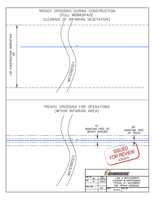
ENBRIDGE ENERGY, LIMITED PARTNERSHIP
                                                          SUMMARY OF CONSTRUCTION METHODS AND PROCEDURES
                                                                                      JANUARY 2020 (REV 6)

                                              TABLE OF CONTENTS

1.0   INTRODUCTION .............................................................................................................1
            DESIGN PROCESS AND METHOD SELECTION OVERVIEW ...........................1
2.0   PROJECT COMPONENTS AND ASSOCIATED CONSTRUCTION PROCEDURES ..... 3
            RIGHT-OF-WAY ACCESS...................................................................................3
            2.1.1 Bridges and Culverts ................................................................................4
            2.1.2 Bridge and Culvert Design ........................................................................7
            CONSTRUCTION YARDS ...................................................................................7
            TEMPORARY AND PERMANENT RIGHTS-OF-WAY .........................................7
            TRAVEL LANES ..................................................................................................8
            ADDITIONAL TEMPORARY WORKSPACES......................................................9
            PIPELINE CONSTRUCTION SEQUENCE ..........................................................9
            MINIMUM DEPTH OF COVER ..........................................................................11
            ASSOCIATED FACILITIES ................................................................................11
            2.8.1 Pump Stations ........................................................................................11
            2.8.2 Valves ....................................................................................................13
            2.8.3 Corrosion Protection ...............................................................................15
            2.8.4 Pipeline Maintenance Shops ..................................................................15
3.0   PIPELINE CONSTRUCTION THROUGH WETLANDS .................................................16
            RIGHT-OF-WAY ACCESS.................................................................................16
            CHOOSING A CONSTRUCTION METHOD ......................................................16
            TRENCH: MODIFIED UPLAND CONSTRUCTION METHOD............................ 21
            TRENCH: PUSH-PULL METHOD......................................................................22
            TRENCHLESS: BORE (NON-PRESSURIZED) .................................................22
            TRENCHLESS: HORIZONTAL DIRECTIONAL DRILL METHOD
            (PRESSURIZED) ...............................................................................................23
            3.6.1 Technical Feasibility Considerations.......................................................27
                  3.6.1.1 Composition of Drilling Fluid .......................................................27
                  3.6.1.2 Functions of Drilling Fluid ............................................................27
                  3.6.1.3 Inadvertent Returns ....................................................................28
4.0   PIPELINE CONSTRUCTION THROUGH WATERBODIES .......................................... 28
            TRENCH: OPEN CUT (NON-ISOLATED) METHOD ......................................... 31
            TRENCH: DRY (ISOLATED) METHODS ...........................................................31
            TRENCHLESS: BORE (NON-PRESSURIZED) .................................................33
            TRENCHLESS: HORIZONTAL DIRECTIONAL DRILL METHOD
            (PRESSURIZED) ...............................................................................................33
            UNFORESEEN CONDITIONS ...........................................................................35
5.0   REFERENCES ..............................................................................................................35

                                                              i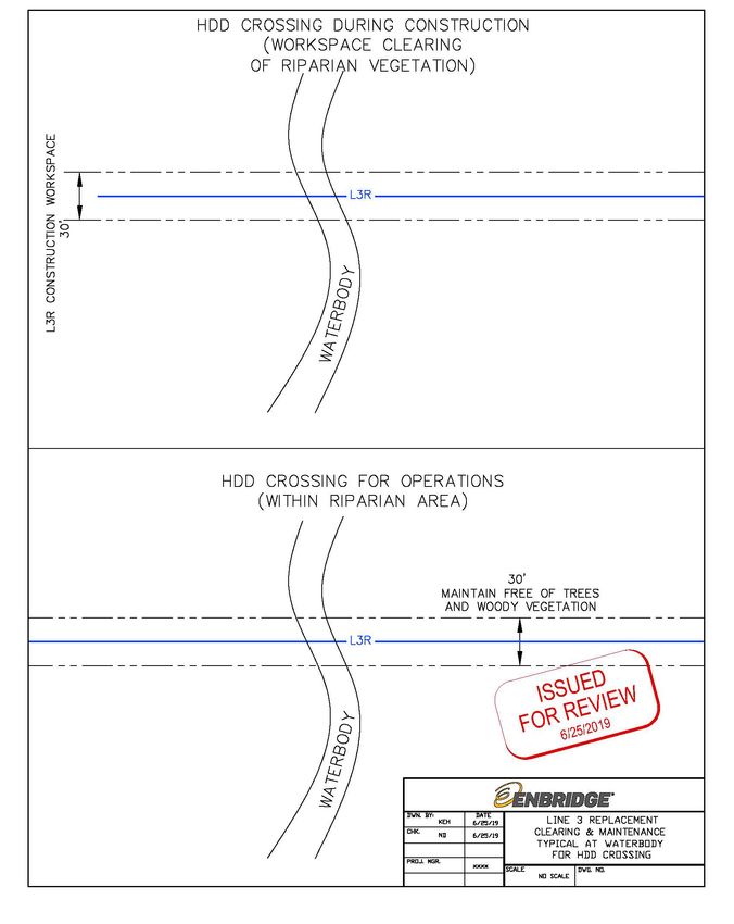
ENBRIDGE ENERGY, LIMITED PARTNERSHIP
                                                        SUMMARY OF CONSTRUCTION METHODS AND PROCEDURES
                                                                                    JANUARY 2020 (REV 6)

                                                      TABLES

Table 2.1-1    Types of Bridges............................................................................................... 5
Table 2.3-1    Typical Construction Workspace and Permanent Right-of-Way Dimensions
               for the Line 3 Replacement Project ................................................................... 8
Table 2.7-1    Depth of Cover Requirements .........................................................................11
Table 3.2-1    Pipeline Wetland Installation Methods .............................................................17
Table 4.0-1    Pipeline Waterbody Installation Methods .........................................................29

                                                     FIGURES

Figure 2.6-1   Typical Pipeline Construction Sequence ..........................................................10
Figure 2.8-1   Line 3 Replacement Project Typical Mainline Valve Layout .............................14
Figure 3.6-1   General Stages of an HDD ..............................................................................24
Figure 3.6-2   HDD Typical Workspace Configuration – Entry/Rig Side .................................25
Figure 3.6-3   HDD Typical Workspace Configuration – Exit/Pullback....................................26
Figure 4.1-1   Vegetation Clearing during Construction and Operations at Trench
               Crossings of Waterbodies ................................................................................32
Figure 4.4-1   Vegetation Clearing during Construction and Operations at Horizontal
               Direction Drill Crossings of Waterbodies ..........................................................34

                                                           ii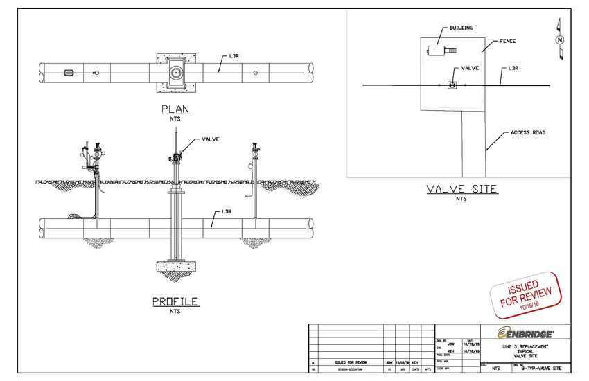
ENBRIDGE ENERGY, LIMITED PARTNERSHIP
                                          SUMMARY OF CONSTRUCTION METHODS AND PROCEDURES
                                                                      JANUARY 2020 (REV 6)

                          ACRONYMS AND ABBREVIATIONS

ATWS                      additional temporary workspace
BMP                       best management practice
contractor yard or yard   pipeline, staging areas, and storage yards
EI                        Environmental Inspector
EMCP                      Environmental Monitor Control Plan
Enbridge                  Enbridge Energy, Limited Partnership
EPP                       Environmental Protection Plan
ESB                       Electrical service building
HDD                       horizontal directional drill
L3R or Project            Line 3 Replacement Project
OHWM                      ordinary high water mark

                                            iii
ENBRIDGE ENERGY, LIMITED PARTNERSHIP
SUMMARY OF CONSTRUCTION METHODS AND PROCEDURES
JANUARY 2020 (REV 6)
1.0 INTRODUCTION
This Summary of Construction Methods and Procedures (“Summary”) describes the various
construction methods that Enbridge Energy, Limited Partnership (“Enbridge”) will utilize to
construct the Line 3 Replacement Project (“L3R” or “Project”) through uplands, wetlands and
waterbodies, and the decision-making process that occurs during design and in the field when
identifying the appropriate crossing technique. The discussion of each construction method
includes:
• Description of the construction methods and procedures;
• Conditions required to employ the method (applicability of the method);
• Site characteristics that require modification to standard construction techniques; and
• Environmental and/or constructability advantages and disadvantages associated with the
method.
The purpose of this document is to provide a more complete description of the construction
techniques that are outlined in Enbridge’s Environmental Protection Plan (“EPP”). The EPP
contains elements of industry and company-wide best management practices (“BMPs”) that would
be implemented during the execution of these construction techniques, such as erosion and
sediment control measures; construction spill prevention, containment, and control; measures to
prevent and contain inadvertent drilling fluid releases; invasive and noxious species control; and
restoration/revegetation measures.
DESIGN PROCESS AND METHOD SELECTION OVERVIEW
The design process is iterative and starts with developing a basic design that satisfies the
intended Project purpose and meets engineering design standards established by the U.S.
Department of Transportation. Enbridge gathers, examines, and analyzes both field and desktop
environmental data to inform the route and construction techniques, which is further refined by
consultations with federal, state, and local regulatory agencies, landowners, and other
stakeholders.
During the design and planning process, Enbridge identifies the preferred method of pipeline
installation based on the engineering design standards (e.g., U.S. Department of Transportation),
presence of wetland features, waterbody features, sensitive resources, landowner/community
considerations, environmental regulations, and constructability considerations, including the
ability to safely and effectively construct through the area. Specifically, these considerations
include the following:
• Sensitive Resources:
o Federally or state-designated high value waters (e.g., Wild and Scenic Rivers, canoe
routes, Nationwide Rivers Inventory)
o Wildlife or aquatic management areas
o Section 303(d) impaired waters and other water quality considerations
1ENBRIDGE ENERGY, LIMITED PARTNERSHIP
SUMMARY OF CONSTRUCTION METHODS AND PROCEDURES
JANUARY 2020 (REV 6)
o Infested waters (presence of aquatic invasive or noxious species)
o Presence of sensitive aquatic resources (e.g., federally or state-listed species, trout
fisheries)
o Sensitive ecological communities (e.g., Sites of Biodiversity Significance)
o Fisheries concerns
o Wetland resources (types, extent)
o Recreational use
o Archaeological and historic resources
o Other issues identified by resource agencies
• Landowner/Community Considerations:
o Homeowner and/or business access
o Noise and/or lighting impacts
o Traffic
o Community access to sites (e.g., recreational areas, hunting)
o Adjoining land use activities (e.g., grazing, organic farms)
o Safety, security, and exposure of the public and workers
o Other issues identified by land-managing agencies (e.g., off-road vehicle access)
• Constructability:
o Season of construction
o Topography
o Geology and soils (e.g., presence of bedrock, cobble/boulders, soil competency/
stability)
o Geometry of the waterbody (straight, meanders)
o Ability to manage water during crossing
o Hydrology and soil saturation/inundation
o Workspace limitations (e.g., roads, railroads, topography, sensitive resources)
o Availability of equipment and access
2ENBRIDGE ENERGY, LIMITED PARTNERSHIP
SUMMARY OF CONSTRUCTION METHODS AND PROCEDURES
JANUARY 2020 (REV 6)
o Duration of activity
o Risk (or probability of success)
o Cost
Enbridge identifies a primary and alternative crossing method for each waterbody crossing
method, with some exceptions (discussed further in Section 4.0), based on these criteria and site-
specific crossing conditions. In some cases, primary and alternative crossing methods are also
defined for wetland crossings (discussed further in Section 3.0). Enbridge gathers information,
such as wetland and waterbody field delineations, stream geomorphic field surveys, and/or
geotechnical borings, and conducts risk assessments to inform these decisions. Enbridge also
reviews construction reports from prior projects that have occurred in the vicinity of the proposed
installations to determine if methods employed were successful or had complications.
The following sections describe the types of construction methods that could be employed to
install the pipeline across uplands, wetlands, and waterbodies, and the specific conditions
required for those methods to be feasible. These sections also describe the circumstances where
a decision may be proposed in the field to change a construction method, or where additional
tools may be utilized to ensure successful installation of the pipeline while minimizing adverse
effects to the natural and/or human environment.
2.0 PROJECT COMPONENTS AND ASSOCIATED CONSTRUCTION
PROCEDURES
The following describes standard construction methods and procedures that may apply to both
upland and wetland environments, as noted. Additional details on the upland construction method
BMPs are provided in Sections 1.8 through 1.21 of the EPP.
RIGHT-OF-WAY ACCESS
As described in Section 1.4 of the EPP, Enbridge will utilize the haul routes, access roads, or
shoo-flies to access the construction workspace.
Enbridge will maintain existing roads, improve existing trails or roads, or build new roads as
needed and approved through applicable permits. Maintenance activities may include back-
blading, and/or placement of fill or construction mats where needed on the existing road grade
and as agreed upon with the road authority. Gravel will only be added to maintain existing roads
that have an existing gravel road base, or to develop permanent access roads, if needed. If gravel
is installed on a road that is not permanently maintained for the Project, it will be removed and
the area will be restored to pre-construction conditions following construction unless the road
authority or landowner requests that it remain in place.
Activities that occur beyond the existing road grade, such as widening (including tree removal),
placement of construction mats in wetlands, placement of structures within the Ordinary High
Water Mark (“OHWM”) of waterbodies, or development of a new road, are considered
improvements requiring environmental survey and applicable permits and authorizations.
Enbridge will confine maintenance and improvements on haul routes to the legal road easement
as established by the corresponding road authority. Haul routes will only be improved where
needed and in most cases, these improvements will be left in place once construction is complete
and where agreed to by the road authority.
3ENBRIDGE ENERGY, LIMITED PARTNERSHIP
SUMMARY OF CONSTRUCTION METHODS AND PROCEDURES
JANUARY 2020 (REV 6)
Construction mats (see Section 3.1) or rock on top of geotextile fabric will be used for roads within
wetlands and will be removed once construction is complete. Ice/frost roads may be used during
frozen conditions as described in Enbridge’s Winter Construction Plan. Typical drawings for rock
and construction mat approaches are provided in Figures 1 and 2 of the EPP.
Temporary access roads and shoo-files utilized during construction will be widened to
approximately 30 feet. After construction, Enbridge will return improved temporary access roads
and shoo-flies to their pre-construction condition unless the road authority, landowner, or land-
managing agency requests that the improvements be left in place. Enbridge will maintain
permanent access roads to aboveground facilities (e.g., pump stations, mainline valves)
throughout Project operation.
2.1.1 Bridges and Culverts
As described above, Enbridge will utilize existing public roads as haul routes and to access the
workspace as much as possible. Generally, the bridges and culverts associated with existing
roads will be sufficient to allow the passage of construction equipment and vehicles. However, in
some cases, improvements to existing infrastructure may be needed, such as:
• Air bridges or construction mats over existing infrastructure;
• Extension of culverts to widen the travel lane; and/or
• Additional in-stream supports.
For new access roads or shoo-flies over a waterbody, and road approaches to the construction
workspace, the following infrastructure may be installed as appropriate for site-specific conditions:
• Clear span bridges: Temporary clear span bridges will typically be used to cross
waterbodies that are less than 13 feet from top of bank to top of bank with stable banks.
No direct excavation of the waterbody bed or in-stream supports are required.
• Non-clear span bridges: Typically used to cross waterbodies with top of bank to top of
bank 13 feet wide or greater as required by Enbridge’s engineering specifications, or
where additional stabilization is required to ensure the bridge installation allows for the
safe passage of construction equipment and vehicles. Installation of infrastructure or
supports within the OHWM are required.
• Culverts/flumes: Cylinder or box-shaped structures placed in the waterbody channel
below the OHWM to allow water flow. The size and shape of the culvert is dependent on
the waterbody.
Table 2.1-1 summarizes the site-specific conditions, advantages, and disadvantages associated
with these bridge and culver types.
4ENBRIDGE ENERGY, LIMITED PARTNERSHIP
SUMMARY OF CONSTRUCTION METHODS AND PROCEDURES
JANUARY 2020 (REV 6)
TABLE 2.1-1
Types of Bridges
Type Description Applicability Advantages Disadvantages
Clear Span Type Construction of temporary bridge Suitable for waterbodies less than 13 • Strong, removable, and portable bridge • Specialized equipment/crew
Bridge (construction utilizing construction mats or an feet wide top of bank to top of bank that can be optimally located required
mats or engineered imported engineered portable bridge with stable banks. Regular bridge • Limited in-stream disturbance • Substantial amount of work may
structures) material from top of bank to top of maintenance required. Preferred be necessary to transport and/or
• Limited sediment release
bank without instream supports bridge type to provide safe crossing for construct
(refer to Figure 3 of the EPP). heavy construction equipment. • Maintains streamflow
• Limited span for construction mat
• Maintains fish passage
bridges and cap may be required
• Regular maintenance of erosion
and sediment controls required
• Possible sediment release from
bank and approach disturbance
or if cap used over construction
mat bridge
• May cause interference on
navigable waterways
• Bridges need to be keyed into the
banks
Non-clear Span Construction of temporary bridge Suitable for waterbody crossings 13 • Strong, removable, and portable bridge • Specialized equipment/crew
Bridge (construction utilizing construction mats or an feet wide or greater top of bank to top that can be optimally located required
mats or engineered imported engineered portable bridge of bank with stable banks. Can be • Limited in-stream disturbance • Substantial amount of work may
structures with material from top of bank to top of used on larger watercourses with be necessary to transport and/or
• Limited sediment release
instream supports) bank with instream supports (e.g., multiple bridge spans and instream construct
mats or flume) (refer to Figure 4 of supports. Regular bridge maintenance • Maintains streamflow
• Limited span for construction mat
the EPP). required. Preferred bridge type to • Maintains fish passage
bridges and cap may be required
provide safe crossing for heavy
construction equipment. • Regular maintenance of erosion
and sediment controls required
• Possible sediment release from
bank, approach, and instream
support disturbance or if cap used
over construction mat bridge
• May cause interference on
navigable waterways
• Bridges need to be keyed into the
banks
5ENBRIDGE ENERGY, LIMITED PARTNERSHIP
SUMMARY OF CONSTRUCTION METHODS AND PROCEDURES
JANUARY 2020 (REV 6)
TABLE 2.1-1
Types of Bridges
Type Description Applicability Advantages Disadvantages
Culvert/Flume Place steel flume pipe or culvert to Appropriate for small or medium-sized • Limited sediment release • Sediment release when filling
allow waterbody flow. Place ramp waterbodies with or without flow and • Maintains stream flow and fish passage around the culvert/flume and
over culvert or flume using with defined channel and banks. Used upon removal
construction mats. Rock may be where streamflow and fish passage • Susceptible to washout during
placed on top geotextile fabric over are of concern. high flow
culvert or flume in waterbodies or
• Icing in winter may block flow and
ditches at road approaches to
fish passage
support construction traffic (refer to
Figure 1 of the EPP). • May require bank grading
• Some culverts may not be able to
withstand heavy construction
traffic
• Requires specialized materials
such as sand bags and select fill
Source: Canadian Association of Petroleum Producers, Canadian Energy Pipeline Association, and Canadian Gas Association, 2005.
6ENBRIDGE ENERGY, LIMITED PARTNERSHIP
SUMMARY OF CONSTRUCTION METHODS AND PROCEDURES
JANUARY 2020 (REV 6)
2.1.2 Bridge and Culvert Design
Equipment bridges and culverts will be designed to meet the requirements of the applicable
agencies and local authorities. Bridges will be installed parallel to the pipeline centerline so that
equipment does not need to turn while working or crossing the bridge. For bridges that are installed
on designated canoe routes, the bridge height will be designed to allow for adequate clearance to
allow recreational users to pass safely under the bridge. Enbridge may also prepare site-specific
bridge or culvert designs at specific wetland or waterbody crossings for agency approval, as
required.
Enbridge has engineering specifications that require in-stream supports on bridges crossing
waterbodies 13 feet wide or greater top of bank to top of bank with stable banks. In-stream supports
will not be installed in or removed from waterbodies during agency-timing restrictions unless
approved by the agency. Bridges will not restrict flow or pool water while the bridge is in place and
will be constructed with clean materials. Bridges will be designed to prevent soil from entering the
waterbody (refer to Figures 3 and 4 of the EPP).
CONSTRUCTION YARDS
In order to construct the pipeline, staging areas, and storage yards (collectively referred to as
“construction yards” or “yards”) will be strategically located outside of the right-of-way along the
route. Yards will be sited in accordance with local permits, as required. These areas are used to
stockpile pipe, and other equipment required during construction. Yards provide parking for
construction equipment and employee trucks, and locations for offices and trailers. Yards may also
be used to clean equipment, or prepare materials for use, such as concrete coating of pipe
segments.
Enbridge will seek previously disturbed areas in proximity to the route to utilize as a yard site, such
as gravel pits, railroad yards, cleared fields, or parking areas. Yards will be cleared and may be
covered in rough stone gravel and/or construction mats as needed. Yards may also be fenced for
security purposes. After construction is complete, yards will be restored back to pre-construction
conditions unless otherwise requested by the landowner.
TEMPORARY AND PERMANENT RIGHTS-OF-WAY
Construction in upland 1 areas will generally require a 120-foot-wide construction workspace. 2 The
construction workspace will allow for temporary storage of topsoil and trench spoil (nonworking
side), as well as accommodate the safe operation of construction equipment and a travel lane
(working side) (refer to Section 2.4). Topsoil will also be stored on the working side. The 50-foot-
1 Uplands: Uplands are defined as an elevated region of land lying above the level where water flows or
collects in basins.
2 The terms “construction right-of-way,” “temporary construction right-of-way,” “construction workspace,”
and “temporary construction workspace” define the primary mainline workspace area required for
installation of L3R. For clarity, Enbridge will generically use “construction workspace” instead of
“temporary construction right-of-way,” temporary construction workspace,” or “construction right-of-way”
as the terminology for 1) the permanent right-of-way; and 2) the temporary construction area (which
includes the following defined terms: Temporary Workspace and Additional Temporary Workspace). All
construction equipment and vehicles will be confined to this approved construction workspace.
7ENBRIDGE ENERGY, LIMITED PARTNERSHIP
SUMMARY OF CONSTRUCTION METHODS AND PROCEDURES
JANUARY 2020 (REV 6)
wide permanent right-of-way 3 will be wholly contained within the 120-foot-wide construction
workspace. Table 2.3-1 presents the typical construction workspace and permanent right-of-way
dimensions that will be used for pipeline construction and operation in upland and wetland areas
(refer to Section 3.0 for a description of construction methods and workspace dimensions in wetland
areas). Figure 5 of the EPP presents the temporary construction workspace 4 and permanent right-
of-way configurations when co-located with existing Enbridge or third-party pipelines or utilities, and
in greenfield 5 locations. Overall, the L3R will be co-located 6 with other Enbridge pipelines; third-
party pipelines or utilities; or roads, railroads, or highways for the majority of the route.
Table 2.3-1
Typical Construction Workspace and Permanent Right-of-Way Dimensions for the Line 3 Replacement Project
Permanent Right-of-Way Temporary Construction Total Land Requirements
Route Segment
(feet) Workspace (feet) (feet)
Co-located with Enbridge 70 (uplands) 120 (uplands)
50 (~25 new)
Pipeline 45 (wetlands) 95 (wetlands
Co-located with Foreign (Third- 70 (uplands) 120 (uplands)
50
Party) Utility 45 (wetlands) 95 (wetlands
Co-located with Foreign Utility in 70 (uplands) 120 (uplands)
50
Saturated Wetlands 45 (wetlands) 95 (wetlands
70 (uplands) 120 (uplands)
Greenfield 50
45 (wetlands) 95 (wetlands
During construction, topsoil and subsoil will be separated and stored within the construction
workspace.
Where co-located with Enbridge’s existing pipelines, Enbridge will use approximately 40 feet of
existing permanent right-of-way as temporary workspace that will revert back to permanent right-
of-way after construction (see Figure 5 of the EPP). The offset distance between L3R and an
existing foreign pipeline or utility will vary, as presented in Figure 5 of the EPP.
TRAVEL LANES
As described in Section 2.3, the working side of the construction workspace will include a travel
lane to allow for the safe passage of construction vehicles and equipment. Temporary equipment
bridges will be used (upon approval by the appropriate agency) at waterbody crossings (including
small waterways such as ditches and intermittent streams) where there is a potential for stormwater
runoff or rain events to transport sediment downstream from equipment crossing the waterway.
Refer to Sections 2.1.1 and 2.1.2 for additional information on bridge and culvert types and design.
3 Permanent right-of-way: The legally acquired land rights used to install, maintain, operate, and access
L3R.
4 Temporary workspace: Land located adjacent to and contiguous with the proposed right-of-way.
5 Greenfield: The term “greenfield” refers to land that has not previously been used for another pipeline,
utility, road, or railroad right-of-way. For the purposes of this document, the term greenfield is applied to
land that is more than 250 feet away from an existing parallel pipeline, utility, road, or railroad right-of-
way.
6 Co-located: Co-located is any portion of the route that is within 250-feet from the centerline of a known
utility.
8ENBRIDGE ENERGY, LIMITED PARTNERSHIP
SUMMARY OF CONSTRUCTION METHODS AND PROCEDURES
JANUARY 2020 (REV 6)
ADDITIONAL TEMPORARY WORKSPACES
Additional temporary workspaces (“ATWS”) 7 will be required outside of the typical construction
workspace to facilitate specific aspects of construction. For example, ATWS will be needed at
select locations such as steep slopes, roads, waterbodies, and some wetland crossings, and
where it is necessary to cross under existing pipelines or foreign utilities, HDD sites, and other
special circumstances to stage equipment and materials, and store spoil. Enbridge will also use
ATWS to accommodate equipment and resources used for appropriating and discharging water.
The dimensions of ATWS will vary according to site-specific conditions.
Enbridge may also require ATWS for:
• construction equipment and working personnel to travel safely within the Project’s
construction site;
• environmental monitoring and mitigation to be employed as required; and
• continuous ingress/egress for emergency equipment and personnel.
Enbridge attempts to locate ATWS outside of wetlands wherever practicable. However, ATWS
may be sited in select wetlands where the wetland is adjacent to a waterbody, road, railroad,
foreign utility crossing, pipeline cross-over, and/or where required based on site-specific
conditions with prior approval from the applicable regulatory agencies.
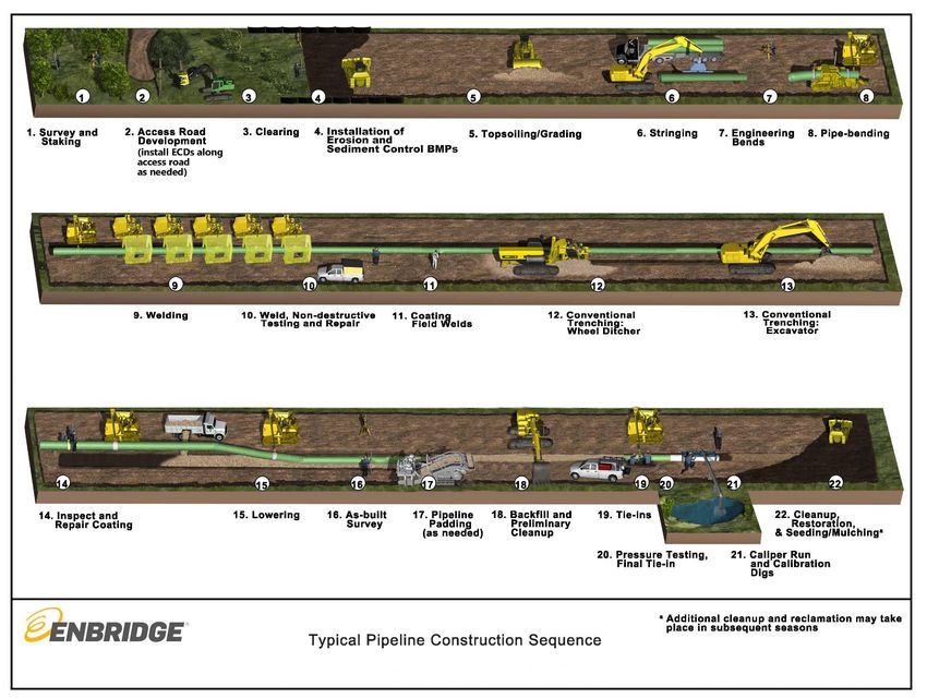
PIPELINE CONSTRUCTION SEQUENCE
Enbridge will install the replacement pipeline using industry-accepted construction methods.
Pipeline construction will typically follow a sequential process, which includes: development of
construction yards, survey and staking of the construction workspace and roads, access road and
haul route improvements, clearing, installation of erosion and sediment control BMPs, site
preparation, pipe stringing, bending, welding, coating, trenching, lowering-in, backfilling,
hydrostatic testing, 8 and cleanup, grading, and restoration. In most areas, these construction
processes will proceed in an orderly assembly-line fashion with construction crews moving along
the construction workspace (see Figure 2.6-1). Appropriate safety measures will be implemented
before excavation begins, including notification through the One-Call system to ensure third-party
utilities and adjacent pipelines are properly marked. Four-way sweeps 9 will also be conducted to
positively locate any existing underground utilities. Pipe, valves, and fittings will be transported to
the workspace and placed along the workspace. Construction crews will use temporary access
roads and shoo-flies for ingress/egress to the Project workspace where travel down the
workspace is not feasible.
7 ATWS: ATWS is temporary construction workspace needed when encountering environmental features
that require special construction methods.
8 Hydrostatic testing: Hydrostatic testing is a process of verifying the integrity of the pipeline before it is
placed into service. Hydrostatic testing involves filling the pipeline with water to a designated pressure
and holding it for a specified period of time.
9 A four-way sweep is a method of locating underground utilities that involves scanning the ground with
electromagnetic induction or ground-penetrating radar equipment to detect the presence of buried
features; it does not involve digging or other ground-disturbing activities. The term “four-way sweep”
comes from the fact that an area typically is scanned (or swept) in at least four directions.
9ENBRIDGE ENERGY, LIMITED PARTNERSHIP
SUMMARY OF CONSTRUCTION METHODS AND PROCEDURES
JANUARY 2020 (REV 6)
Figure 2.6-1: Typical Pipeline Construction Sequence
10ENBRIDGE ENERGY, LIMITED PARTNERSHIP
SUMMARY OF CONSTRUCTION METHODS AND PROCEDURES
JANUARY 2020 (REV 6)
MINIMUM DEPTH OF COVER
In accordance with federal requirements (49 Code of Federal Regulations 195.248), the depth of
cover between the top of the pipe and the ground level, road bed, or river bottom can range
between 18 to 48 inches, depending on the location of the pipe and the presence of rock, which
is provided below (see Table 2.7-1).
Table 2.7-1
Depth of Cover Requirements
Cover in inches
Normal Rock
Location Excavation Excavation a
Industrial, commercial, and residential areas 36 30
Crossing of inland bodies of water with a width of at least 100 ft. from high water mark to high 48 18
water mark
Drainage ditches at public roads and railroads 36 36
Deepwater port safety zones 48 24
Gulf of Mexico and its inlets in waters less than 15 feet deep as measured from mean low water 36 18
Other offshore areas under water less than 12 feet deep as measured from mean low water 36 18
Any other area 30 18
a
Rock excavation is any excavation that requires blasting or removal by equivalent means.
Minnesota Statute § 216G.07, Subd. 1 requires that the pipeline trench be excavated to a depth
of at least 54 inches of backfill from ground surface to the top of pipeline in all areas where the
pipeline crosses the right-of-way of any public drainage facility; or any county, town, or municipal
street or highway; and where the pipeline crosses cultivated agricultural land. This depth
requirement may be waived as described in Minnesota Statute § 216G.07, Subd. 2; however, the
pipe must still be buried to a minimum depth that complies with the federal requirements outlined
in Table 2.7-1. While Enbridge will seek waivers for Minnesota state depth of cover requirements
in some circumstances, it will meet all federal depth of cover requirements and also target a
nominal 48 inches of cover across the Project.
In addition, agencies have requested additional depth of coverage at certain wetland and
waterbody crossings. Enbridge will work with the agencies to determine the appropriate depth of
cover at these locations. This design change will be reflected in the construction alignment sheets
and applicable site-specific drawings. Following installation of the pipeline, Enbridge will confirm
that the pipe depth meets federal and state requirements through civil survey.
ASSOCIATED FACILITIES
Facility construction will follow the same initial sequential process as mainline pipeline
construction, including survey and staking, clearing, and site preparation.
2.8.1 Pump Stations
Pump stations will be located at regular intervals along the pipeline to boost the pressure lost due
to friction as the liquids move through the pipe. All pump stations will be installed on property that
has been or will be purchased by Enbridge in fee. Construction of each pump station will occur
over an approximate 10-month period.
11ENBRIDGE ENERGY, LIMITED PARTNERSHIP
SUMMARY OF CONSTRUCTION METHODS AND PROCEDURES
JANUARY 2020 (REV 6)
Each pump station property will include a:
• Pumphouse building;
• Electrical service building (“ESB”);
• Substation;
• Permanent access road and parking area;
• Snow storage area(s);
• Containment basin; and
• Infiltration basin or wet sedimentation basin.
Prior to excavation, four-way sweeps will be conducted to positively locate any existing
underground utilities. Temporary construction trailers will be placed, material laydown areas 10
prepared, and temporary utilities (e.g., power, telephone) will be installed at the site. Topsoil will
be stripped and stored prior to initiating excavation work.
The pumphouse building footprint will measure approximately 120 feet by 70 feet and the
excavation will vary between approximately 5 to 10 feet deep depending on site-specific
conditions. Typical construction procedures for the building foundation are to excavate the
foundation base depth, establish concrete foundations, fill, and construct. Dewatering of the
excavations will occur as described in Section 5.0 of the EPP and applicable permit conditions.
Several components at the pump station site will require foundation footings, including the
pumphouse, ESB, and substations. Foundation footings will consist of either poured concrete
piers or helical footings that will average between 10 to 15 feet deep but may extend up to 40 feet
deep depending on site specific conditions.
The piping associated with the pump stations will either be welded onsite or pre-fabricated spools
made from fabrication shops will be installed. All station piping will be pressure tested after on-
site installation. Pressure testing will be completed with a liquid test medium that will be trucked
on- and off-site. Piping will be tested for 4.25 hours if above grade; below grade piping will be
tested for 8.25 hours. There will be three pressure tests per facility; one test for the mainline piping
inside the station, one test for the station piping, and one for the drain line piping.
The modular-designed ESBs will be placed onsite and all associated electrical and controls
equipment will be installed. Power and control cables will be routed, and additional pre-operational
testing can begin once the system(s) are energized. All sites will require the construction of a new
electrical substation.
The containment basin, wet sedimentation basin, or infiltration basin associated with each facility
will be designed and constructed in accordance with the applicable federal and Minnesota
Pollution Control Agency requirements.
Upon completion of all pre-operational testing, the equipment will be flooded with crude oil
according to the detailed flood plans developed for each site. Equipment operation will then be
verified. Final site civil work and painting will be completed, and the pump station property will be
fenced in and gated to restrict access to the site. The area within the fence will be graveled and/or
10 Material laydown area: A material laydown area is a piece of land where materials are stored and staged
for construction.
12ENBRIDGE ENERGY, LIMITED PARTNERSHIP
SUMMARY OF CONSTRUCTION METHODS AND PROCEDURES
JANUARY 2020 (REV 6)
maintained as grass. Once all final checks have been completed, the facility will be turned over
to Enbridge Operations for service.
2.8.2 Valves
Valves 11 will be installed concurrently with the mainline pipe. Each valve site will consist of:
• one 8-foot by 14-foot building constructed 3 feet above grade on helical footings that do
not require excavations or grout to install;
• one 36-inch mainline gate valve with electrical actuator and pressure transmitters on both
upstream and downstream of the valve;
• ESB and associated electrical and controls equipment;
• service entrance and permanent access road; and
• security fencing and signage.
Refer to Figure 2.8-1 for a typical mainline valve layout.
Excavations at valve sites will be required to connect valve components to the belowground
pipeline. The excavation dimensions are approximately 15 feet wide by 15 feet long by 15 feet
deep, stepped back to 20 feet wide by 20 feet long at the ground surface. The mainline valve
footing will be concrete 1.5 feet thick on a 1-foot thick gravel pad with the footing surface located
just over 5 feet (5 feet 1 3/8 inches) below the installed centerline of the pipe. Total depth of the
excavation is therefore anticipated to be approximately 13 to 15 feet below ground surface.
Additional excavation will include cable routing trenches that will be approximately 24 inches deep
and 12 inches wide.
After backfilling is complete, the valve will be filled with water and hydrostatically tested as part of
the mainline spread hydrostatic test. The ESB will be placed and all associated electrical and
controls equipment will be installed. Power and control cables will be routed, and additional pre-
operational testing will begin once the system(s) are energized. Some sites will require the
construction of a new electrical service.
11 Valve: A valve is a piece of equipment used to control the flow of crude oil inside the pipeline. The valve
acts as a gateway that can be opened and closed. A mainline valve describes an entire aboveground
facility on the pipeline that is equipped with shutoff valves capable of stopping pipeline flow in the event
of an emergency or for maintenance. A slide gate valve is a particular type of shutoff valve that operates
by sliding a steel plate across the entire diameter of the pipe to seal off flow.
13ENBRIDGE ENERGY, LIMITED PARTNERSHIP
SUMMARY OF CONSTRUCTION METHODS AND PROCEDURES
JANUARY 2020 (REV 6)
Figure 2.8-1: Line 3 Replacement Project Typical Mainline Valve Layout
14ENBRIDGE ENERGY, LIMITED PARTNERSHIP
SUMMARY OF CONSTRUCTION METHODS AND PROCEDURES
JANUARY 2020 (REV 6)
Upon completion of all pre-operational testing, the valve will be ready for use. Equipment
operation will be re-checked and final site civil work including fencing installation, permanent
access road construction, and painting will be completed. The valve site within the fenced area
will be graveled. After the final site civil work is complete, the site will be cleaned up and restored.
After all final checks have been completed, the valve site will be turned over to Enbridge
Operations for service.
2.8.3 Corrosion Protection
A cathodic protection 12 and impressed current mitigation systems will be constructed for L3R.
Construction of this system includes both anode arrays installed in both conventional beds near
the surface as well as in deep wells. Construction of cathodic protection systems includes
excavation of soils at the site of installation. Methods utilized typically involve digging a trench for
a cable using a mini-excavator, or ground trenching equipment such as a Ditch Witch. The
technique used to install the cables associated with the cathodic protection system is similar to
the methods used for installing fiber optic or telephone lines used for communications, which
typically requires an approximately 30-foot-wide construction workspace.
Conventional surface bed type cathodic protection systems will be installed between 300 and 600
feet perpendicular to the pipeline. Anodes will be installed in either vertical or horizontal fashion
and cables will be trenched to connect the anodes electrically to the protected metallic structures.
Enbridge will also construct deep well cathodic protection systems where the anodes will be
installed vertically in a well using construction methods similar to that of water wells. Deep well
cathodic protection systems are normally installed closer to the pipeline, with the anodes
themselves installed deeper (200 to 400 feet deep) than a conventional surface bed.
Both types of systems utilize native backfill for areas where trenching for the cable occurs.
However, the area directly around the anodes will be backfilled with a more suitable backfill such
as coke breeze. 13 Additionally, in a deep well cathodic protection system, a natural clay plug will
be installed above the anodes to seal the well and prevent water from entering the hole.
2.8.4 Pipeline Maintenance Shops
Pipeline Maintenance (“PLM”) shops are strategically located along the pipeline route and are
staffed by operations personnel. The PLM shops are stocked with equipment needed during
operations and maintenance of the pipeline.
Construction will proceed similar to the pump stations, beginning with initial survey, staking, and
four-way sweeps. The site will then be cleared and stripped of topsoil to prepare for excavation
activities. Excavations will be made for the building foundations, septic and well, power, and
12 Cathodic protection: Cathodic protection is a method for safeguarding the pipeline against corrosion. In
a cathodic protection system, the metal to be protected (the pipeline) is connected to a metal that
corrodes more easily (anode array or anode groundbed). The metal that corrodes more easily corrodes
instead of the pipeline. Cathodic protection can be achieved by using reactive anode metals that are
electrically connected to the pipeline (also known as a galvanic anode systems) or by using inert anode
metals and impressing an electric current on the system (also known as an impressed current system).
Enbridge’s proposed cathodic protection system includes anode arrays installed in conventional beds
near the ground surface as well as in deeper wells.
13 Coke Breeze: Coke breeze is common carbonaceous backfill material used in cathodic protection. It
provides a conductive path for current flow and ensures optimal effectiveness of the cathodic protection
system.
15ENBRIDGE ENERGY, LIMITED PARTNERSHIP
SUMMARY OF CONSTRUCTION METHODS AND PROCEDURES
JANUARY 2020 (REV 6)
communication. The excavation for the building will be approximately 125 feet by 75 feet by 6 feet
deep to accommodate the foundations. Once foundations are poured, the excavation will be
backfilled to rough grade and the building will be constructed.
After the building is constructed, the site will be stabilized, fenced, signed, and turned over to
Enbridge Operations for their use.
3.0 PIPELINE CONSTRUCTION THROUGH WETLANDS
RIGHT-OF-WAY ACCESS
Enbridge will use the construction workspace and only approved roads to access wetland areas.
Construction mats will be placed along the travel lane within delineated wetlands within the
construction workspace and along access roads (refer to Section 2.1). Enbridge may use the
following types of construction mats:
• Timber Mats: Timber mats are available in a variety of sizes and are constructed of
hardwood materials that are bolted together. Timber mats are suitable for all vehicle types
present on the construction workspace, have high durability under traffic, and are easily
installed and removed using typical construction equipment. Timber mats are suitable for
use in all soil conditions for all pipeline construction activities.
• Laminated Mats: Laminated mats are available in a variety of sizes and are constructed
of laminated wood materials. Laminated mats are suitable for all vehicle types but are
limited in their weight bearing capacity (e.g., 600 pounds per square inch). They have
high durability and are easily installed and removed using typical construction equipment.
Laminated mats are suitable for use in most soil conditions but should not be used in
extremely saturated conditions. Laminated mats can be used on access roads, at drill
pads, and for storage and staging of equipment.
CHOOSING A CONSTRUCTION METHOD
Table 3.2-1 summarizes the wetland crossing techniques Enbridge intends to utilize during
construction, the site-specific conditions required for the method to be feasible, and the
advantages and disadvantages associated with each technique. Enbridge will typically install the
pipelines through wetlands with moderate- to high-bearing strength soils using standard upland
crossing methods utilizing construction mats or equivalent to avoid rutting, minimizing disturbance
to soils and vegetation, and to ensure safe and stable working surfaces for construction
equipment and personnel.
Enbridge may install the pipeline through saturated wetlands with low bearing strength soils by
using push-pull techniques, if practicable, or by using standard upland crossing techniques with
frost/ice roads during frozen conditions (see Enbridge’s Winter Construction Plan for additional
information). In some cases, Enbridge may install sheet piling within the trench to stabilize the
trench walls. Enbridge may install the pipelines through narrow wetlands or ditches adjacent to
roads or railroads and sensitive wetlands or riparian areas adjacent to waterbody crossings using
trenchless techniques such as a non-pressurized horizontal bore method or the HDD
(pressurized) method.
16ENBRIDGE ENERGY, LIMITED PARTNERSHIP
SUMMARY OF CONSTRUCTION METHODS AND PROCEDURES
JANUARY 2020 (REV 6)
TABLE 3.2-1
Pipeline Wetland Installation Methods
Method
(Season) Description a Site Characteristics Applicable Wetland Type(s)b Advantages Disadvantages
Trench: Conduct construction from Suitable in wetlands with The following wetland types are • Relatively quick • Clearing and brush removal
Modified construction mats or unsaturated mineral soils typically suitable, as along as the construction/installation required along travel lane in
Upland equivalent (refer to Figures constructed during non-frozen criteria described in the Site • No need for specialized forested wetlands
Construction 30 and 31 from the EPP). conditions. Also, suitable in Characteristics column is also equipment • Potential need for wider than
Method (open Multiple layers of saturated wetlands (typically met: normal trench and therefore
• Minimizes impacts on soils
cut) (Spring- construction mats may beENBRIDGE ENERGY, LIMITED PARTNERSHIP
SUMMARY OF CONSTRUCTION METHODS AND PROCEDURES
JANUARY 2020 (REV 6)
TABLE 3.2-1
Pipeline Wetland Installation Methods
Method
(Season) Description a Site Characteristics Applicable Wetland Type(s)b Advantages Disadvantages
Trench: Push- Use a backhoe (or Suitable in saturated The following wetland types are • Minimizes impacts on • Topsoil segregation typically not
Pull Method: equivalent) to excavate the wetlands (typically >12-inch typically suitable, as along as the wetland soils and practical; inability to maintain a
Backhoe trench operating from inundation) with relatively criteria described in the Site vegetation cohesive spoil pile due to liquid
(Spring-Fall) construction mats “walked” competent peat soils, shallow Characteristics column is also • No specialized equipment nature of soil
down the trenchline (refer peat over mineral soils, or met: needed and allows for • Potential for stranding of the
to Figures 35 and 36 of the forested peatlands with • Shallow Marsh construction in unfrozen, excavator if extremely loose, deep
EPP). Push-pull or float moderate bearing strength saturated wetlands peat soils are encountered
• Deep Marsh
and sink the pre- soils. unexpectedly
• Shallow, Open Water • Reduced heavy equipment
assembled pipe then
• Coniferous Bog traffic • Additional workspace required for
backfill. May or may not
pipe assembly or pipe may be
use a travel lane • Open Bog fabricated off-site and brought in
depending on conditions
as a drag section
with backfilling occurring
from the spoil storage side • Due to lack of travel lane,
or the working side. When additional adjacent workspace
a travel lane is used, required for equipment
vegetation will be cut turnarounds
above the ground surface • May require spread move around
to maintain the root
structure and seed bank in
the soil profile. May or may
not require trench
dewatering.
18ENBRIDGE ENERGY, LIMITED PARTNERSHIP
SUMMARY OF CONSTRUCTION METHODS AND PROCEDURES
JANUARY 2020 (REV 6)
TABLE 3.2-1
Pipeline Wetland Installation Methods
Method
(Season) Description a Site Characteristics Applicable Wetland Type(s)b Advantages Disadvantages
Push-Pull Excavate the trench using Suitable in saturated (typically The following wetland types are • Allows for construction in • Specialized equipment (i.e.,
Method: a backhoe (or equivalent) > 12-inch inundation) typically suitable, as along as the saturated wetlands during swamphoe) required
Swamphoe mounted on tracked emergent and scrub-shrub criteria described in the Site unfrozen conditions • Topsoil segregation typically not
(Spring-Fall) pontoons operating along wetlands with loose, deep Characteristics column is also • Reduced heavy equipment practical; inability to maintain a
the trenchline (refer to peat soils or floating mat met: traffic cohesive spoil pile due to liquid
Figures 35 and 36 of the peat, low-bearing strength • Shallow Marsh nature of soil
EPP). Push-pull or float soils. • Deep Marsh • Potential for spoil settlement
and sink the pre-
• Shallow, Open Water preventing complete replacement
assembled pipe then
• Coniferous Bog of backfill and potentially resulting
backfill. May or may not
in open water along the trenchline
use a travel lane • Open Bog
depending on conditions • Additional adjacent workspace
with backfilling occurring required for pipe assembly or pipe
from the spoil storage side may be fabricated off-site and
or the working side. When brought in as a drag section
a travel lane is used, • Additional adjacent workspace
vegetation will be cut may be required for equipment
above the ground surface turnarounds
to maintain the root • Slower than normal construction
structure and seed bank in progress in the wetland due to
the soil profile. May or may equipment speed
not require trench • May require spread move around
dewatering.
Trenchless: Bore under feature from Suitable for narrow highways, The following wetland types are • Avoids surface ground • Requires additional workspace for
Bore (Non- bore pit on one side to roads, railroads, and typically suitable, as along as the disturbance in the wetland bore pits, spoil piles, and sump(s)
Pressurized) bore pit on the other side watercourses. Not suitable criteria described in the Site or ditch adjacent to the • Large excavations required on
with or without casing (see where there are high water Characteristics column is also feature crossed both sides of the crossing
Figures 40 and 41 of the tables, loose sand/gravel met: • No sediment release • Deep bore pits may require sump
EPP). Non-pressurized substrates, or adjacent steep • Wet/Wet Mesic Prairie • No potential for inadvertent pump or well point dewatering
water or bentonite may be slopes. • Fresh (Wet) Meadow release outside of the bore system and/or sheet-piling
introduced if soil conditions
• Sedge Meadow pits • Slower than trench crossing
dictate; any release will
travel back along the path • Alder Thicket techniques
of the pipe and into the • Shrub-Carr
bore pit. • Floodplain Forest
• Hardwood Swamp
• Coniferous Swamp
19ENBRIDGE ENERGY, LIMITED PARTNERSHIP
SUMMARY OF CONSTRUCTION METHODS AND PROCEDURES
JANUARY 2020 (REV 6)
TABLE 3.2-1
Pipeline Wetland Installation Methods
Method
(Season) Description a Site Characteristics Applicable Wetland Type(s)b Advantages Disadvantages
Trenchless: Place a rig on one side of Suitable to cross sensitive All wetland types that meet the • No sediment release unless • Potential for inadvertent release
HDD the wetland and drill a wetland areas and riparian criteria described in the Site an inadvertent return of drilling fluids (refer to Section
(Pressurized) small-diameter pilot-hole wetlands adjacent to Characteristics column. occurs 11.0 of the EPP)
under the feature along a waterbody crossings • Avoids surface ground • Requires ATWS on both sides of
prescribed profile (see depending on site-specific disturbance in riparian the crossings to stage
Figure 26 of the EPP). topography and the local wetlands adjacent to construction, fabricate the
Upon completion of the geologic substrate. Feasibility sensitive or large pipeline, and store materials
pilot-hole, use a limitations in high flow waterbodies • Tree and brush clearing is
combination of cutting and artesian conditions, areas of
• Limits vegetation necessary for operations
reaming tools to glacial till or outwash
disturbance to within the • Requires obtaining water to
accommodate the desired interspersed with boulder and
permanently maintained formulate the drilling fluid,
pipeline diameter. Drilling cobbles, fractured bedrock, or
easement buoyancy control, as well as
mud is necessary to non-cohesive coarse sands
remove cuttings and and gravels. Geotechnical • Significantly reduces clean- hydrostatic testing
maintain the integrity of the borings and hydrofracture risk up and restoration between • Feasibility and success depends
hole. Once the hole is analysis are performed to entry and exit points on substrate
reamed to the appropriate determine HDD feasibility and • Requires specialized equipment
size, the welded pipe potential for inadvertent (limited availability)
section is then pulled back returns. • Pull string area along the
through the hole. alignment for the same length of
the crossing to allow continuous
pullback
• Requires a straight alignment for
the length of the HDD
• May require several weeks to
complete the HDD
Notes:
a
For all methods except HDD, vegetation and trees within wetlands will be cut off at ground level along the entire workspace, leaving existing root systems intact; clearing
debris will be removed from the wetland for disposal. For the HDD method, vegetation and trees within the wetland will be removed along 30 feet of the permanent right-of-
way to allow for aerial inspection of the pipe during operations.
b
Typical wetland types (Eggers and Reed, 2014) suitable for the referenced crossing method; the construction technique selected will depend on the site-specific conditions
described in the site characteristics column.
Source: Canadian Energy Pipeline Association, Canadian Association of Petroleum Producers, Canadian Gas Association, 2018.
20ENBRIDGE ENERGY, LIMITED PARTNERSHIP
SUMMARY OF CONSTRUCTION METHODS AND PROCEDURES
JANUARY 2020 (REV 6)
TRENCH: MODIFIED UPLAND CONSTRUCTION METHOD
The modified upland construction method (also referred to as open cut or the standard wetland
construction method) differs from standard upland construction method to minimize disturbance
to the wetland features. These main differences, described in more detail in Section 3.0 of the
EPP, include:
1) Reducing the construction workspace compared to uplands (from 120 to 95 feet) (refer to
Table 2.3-1, and Figure 5 of the EPP);
2) Performing workspace clearing using low ground-pressure equipment or operating off
construction mats or ice/frost roads to limit disturbance to the wetland (Section 3.2 of the
EPP and the Winter Construction Plan);
3) Clearing vegetation in wetlands to the ground level, but leaving intact root wads except
over the trench line (Section 3.2 of the EPP);
4) Installing and maintaining erosion and sediment control BMPs to prevent sediment flow
from uplands into wetlands (Section 3.4 of the EPP);
5) Trench-Line-Only topsoil segregation, involving stripping and segregating up to 1 foot of
the organic layer/topsoil from the trench line and storing the material separate from trench
spoil to preserve the native seed stock from wetlands without standing water. In standing
water wetlands, the Contractor will attempt to segregate as much of the soil surface as
possible based on site and saturation conditions (Section 3.6.1 of the EPP); and
6) Implementing restoration techniques suitable to wetland conditions, as described in
Section 7.7 of the EPP.
As described in Table 3.2-1, this technique is suitable in wetlands with unsaturated mineral soils
constructed during unfrozen conditions or can be used in saturated wetlands (typicallyYou can also read