ASSEMBLY INSTRUCTIONS PMT EVO 2.0 S 10 - Premium Mounting ...
←
→
Page content transcription
If your browser does not render page correctly, please read the page content below
ASSEMBLY INSTRUCTIONS
PMT EVO 2.0 S 10°
SAFETY INSTRUCTIONS                    3
        REQUIRED MATERIAL                      4
        REQUIRED TOOLS                         5
        ASSEMBLY                            6-19
PMT // Table of contents // PMT EVO 2.0 S      Page 2 // 20
!                 GENERAL SAFETY INSTRUCTIONS

Please note that our general safety instructions must be observed. First read through the general safety
instructions and the assembly instructions.

       The building data given in the project must be compared with the actual building data.
       Deviations shall be agreed upon with Premium Mounting Technologies GmbH & Co. KG, and the
       planning shall be adjusted. In the event of non-compliance, Premium Mounting Technologies
       GmbH & Co. KG reserves the right to exclude liability.

       Before installation, check the compatibility of the system with the roof.

       Systems may only be installed and commissioned by persons who can guarantee that they are
       carried out correctly because of their professional suitability (e.g. training or work) or experience.

       Before installation, it must be checked whether the product meets the static requirements on
       site. For roof systems, the load-bearing capacity of the roof must also be checked. National and
       site-specific building regulations, standards, and environmental protection regulations must be
       complied with.

       With a roof inclination more than 2.5°, we strongly recommend connecting the system to the roof
       structure in order to prevent the “caterpillar effect” caused by thermal linear expansion.

       Occupational safety and accident prevention regulations, corresponding standards, and regula-
       tions of the trade association must be observed.

       The assembly instructions of the module manufacturers must be observed.

       In the event of non-compliance with our General Safety Instructions as well as with the
       installation and mounting of components of the competition, Premium Mounting Technologies
       GmbH & Co. KG reserves the right to exclude liability.

PMT // Safety instructions // PMT EVO 2.0 S                                                            Page 3 // 20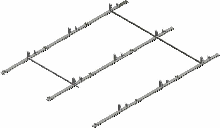
REQUIRED MATERIAL

                                                                      Required

                                                      A                                           H
                                               Start and end rail                           Rear wall tower

                                                      B
                                              Main floor rail with
                                              pre-installed base                 Optional

                                                      C                                           O1
                                             Tower (Middle Part)                            Cable duct cover

                                                      D                                           O2
                                            Cross and ballast brace                          Ballast stone

                                                       E                                          O3
                                            Cross brace connector                    Lightning protection screw

                                                      F                                           O4
                                       Module and ballast clamps                      Ballast trough V01/V02
                                       as middle and end clamps

                                                      G                                           O5
                                                  Rear wall                                    Side wall

PMT // Required material // PMT EVO 2.0 S                                                                  Page 4 // 20
REQUIRED TOOLS

                                Notwendig
                                Required                    Optional

        Tape measure                        Rubber hammer

           Chalk line                        Assembly jig

   Torque wrench with
   SW5 hexagon socket
       attachment

PMT // Required tools // PMT EVO 2.0 S                                 Page 5 // 20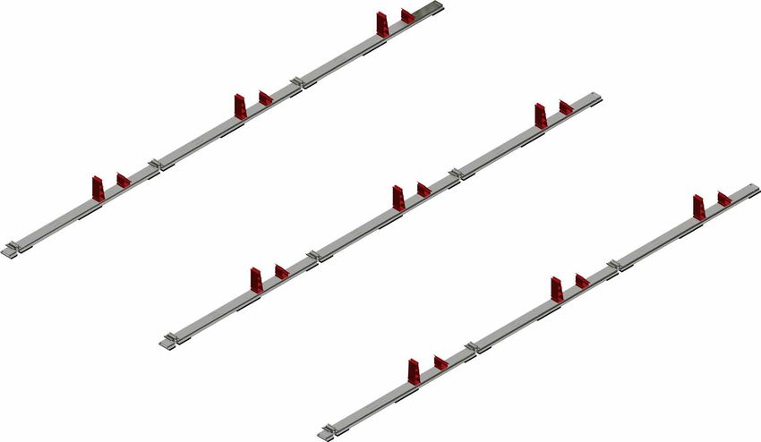
In only         5 steps
                        to the finished system

                                Required            Optional

PMT // Assembly instructions // PMT EVO 2.0 S                  Page 6 // 20
STEP
      1.                FLOOR RAILS A AND B TO BE LAYED OUT;
                        CONNECTED AND SET-UP

                                                      B

                                                B

                                 B

                    A

                                                          x = module length l
                                                              + 20 mm
                                                              - 115 mm

 INFO           i
    All PMT floor rails are equipped with an 11 mm thick high-tech protective mat. This ensures free water drainage and pre-
    vents damage to the roofing from mechanical influences and long-term damage from plasticiser migration. Furthermore,
    all profiles are equipped with drainage holes on the undersides in order to prevent backwater and frost damage.

     A
                                     B

PRELIMINARY WORK:
Clean roof surface and remove interfering objects; measure roof surface and compare with planning documents; mark system
corner dimensions.

SEQUENCE:
Lay out the components of the start and end rails A , main floor rail B , after the other according to the planning documents.
The order here starts from South to North: A      B   B    B   B    … B . The sequence is the same in each row and always ends
with component B at the end of the row. Rails A and B must be pushed one into the other until the Click catch engages with
audible noise (detailed image 3). The snap-fit connection must be checked for proper form fit and strength. The floor rails rows
must now be set up at the distance specified in the planning documents (see              ).

 EXPERTS ADVICE

    The use of the assembly jig (PMT item no. 52215-0025) between the inner sides of the floor rails is helpful here.
    Setting: Module length l + 20 mm − 115 mm; example: 1650 mm + 20 mm − 115 mm = 1555 mm
    The assembly jig must always rest on the roof cladding and be placed on the outer edge of the floor rail. Always place the
    assembly jig in the area of the tower where the cross braces will later also be bolted.

PMT // Assembly instructions // PMT EVO 2.0 S                                                                            Page 7 // 20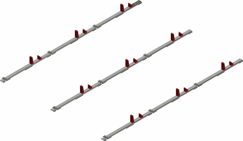
STEP
    2.                  ASSEMBLY MIDDLE PART TOWER C AND REAR
                        WALL TOWER H

                                                                                         H

                                                                                C

                                                                   H
                                                                                B
                                                           C

 INFO           i
    The tower components serve as upper support elements for the modules in all PMT systems, the rear wall tower serves
    as receiving element for the rear wall.

                          2
            1
SEQUENCE:
Push the middle part tower C to the two narrow recesses 1 (to the long end of the rail) with the latching lug pointing away on the
floor profile. Press them vertically in the floor rail B and push them towards the end of the rail until the click latch engages with
audible noise. Then press the rear wall tower H vertically with the slope pointing away from the tower in the two recesses 2 and
move towards the tower C until it clicks into place with an audible noise.

  CORRECT                                                                                      INCORRECT

 ATTENTION                  !
    Always pay attention to the correct position and lock of the click latch.

PMT // Assembly instructions // PMT EVO 2.0 S                                                                              Page 8 // 20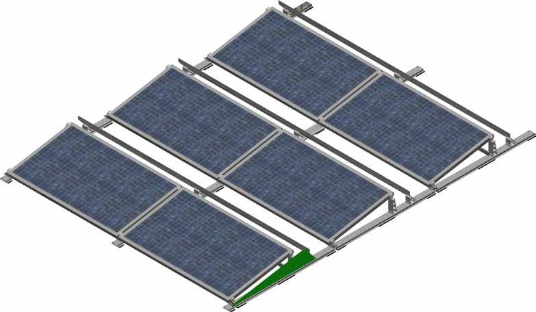
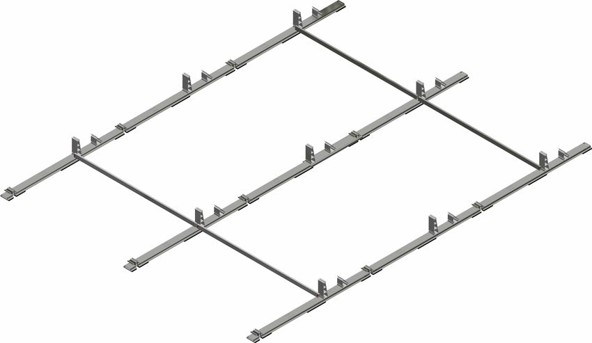
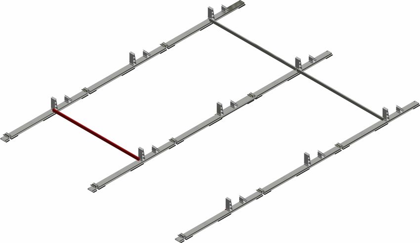
STEP
     3.                 ASSEMBLING OF CROSS AND BALLASTBRACE D
                        AS CONNECTING COMPONENT

                                                 C
                                                                   INCORRECT POSITION

                                                              D

                                                                        C

                                                CORRECT POSITION

 INFO           i
    The brace has two functions. When installed in a simple version, it increases the static bond of the system and facilitates
    further work such as pulling the cables and laying the modules because the floor rails can slip more easily. In the double
    version, it serves to take up additional ballast (see Option 2).

CROSS AND BALLAST BRACE

          at least
          15 mm

SEQUENCE:
Insert the cross and ballast brace D in the middle between the tower C in the suspension lugs. Screw the cross and ballast
brace D together as far as they will go using the two M8x30 screws. Observe tightening torque of 10 Nm. (Please note the SER-
VICE information.)
CROSS BRACE CONNECTOR

The cross brace connector E must be installed according to the planning documents. The cross brace connector needs to
be pushed up to the middle into the installed cross and ballast brace D . Slide the following cross and ballast brace D over
the cross brace connector E . The component combination must be fastened to the tower C using two M8x30 screws. Observe
tightening torque of 10 Nm. (Please note the SERVICE information.)

    NOTE: The cross brace must always be mounted on the tower. Always make sure that the cross and ballast brace D on
    the tower C has sufficient contact surface (at least 15 mm).

PMT // Assembly instructions // PMT EVO 2.0 S                                                                             Page 9 // 20
OPTIONAL STEP
      1.                CABLE DUCT COVER O1

 INFO           i
    In order to protect the string lines from permanent and harmful environmental influences – in particular UV radiation – all
    PMT floor rails are equipped with cable duct cover holders. The installation of the cable duct cover is possible after each
    working step of the system construction.

PRELIMINARY WORK:
Check proper position of string lines; check permanent and safe fastening of string lines to prevent damage to lines by move-
ments (wind).

Optional, an additional fastening by means of Edge-Clips on the floor rails can be done in order to guarantee a secure positioning
of the cables.

SEQUENCE:
Place the cable duct cover O1 in the lower guide groove on the base rail B ; tilt the cable duct cover O1 over to the upper guide
groove; load the cable duct cover O1 in the middle until the click catch engages with an audible noise.

 ATTENTION                  !
    When installing the cable duct, make sure that the cables are not damaged.

PMT // Assembly instructions // PMT EVO 2.0 S                                                                            Page 10 // 20
OPTIONAL STEP
2. BALLAST STONE O2
INFO i
The additional weight on the system depends on many parameters such as building height, location, environment, and roof
cladding. This means that no additional ballast or high ballast is required.
PRELIMINARY WORK:
Assemble the cross and ballast brace D to tower E and rear wall tower H as described in Step 3.
SEQUENCE:
Place the ballast stones O2 evenly distributed on the ballast braces D ; maximum weight per ballast brace arrangement: 135 kg
ATTENTION !
The ballast must always be positioned strictly in accordance with the planning documents. A different distribution or
the omission of ballast elements can affect the positional stability of the entire installation and represent an enormous
risk. Deviations from the planning has to be agreed with PMT in writing and be carried out afterwards. Positioning of the
ballast components shall be chosen appropriate to permanently prevent slipping, tipping, or wobbling. The ballast must lie
over the entire surface; just leaning the ballast is not sufficient.
PMT // Assembly instructions // PMT EVO 2.0 S Page 11 // 20OPTIONAL STEP
2. POSITIONING OF THE BALLAST STONE O2
1 BALLAST STONE PER RAIL SECTION 9 – 17 BALLAST STONES ON THE DOUBLE BRACE
Place the ballast stone centrally on the rail, push it to the
base C and fasten it by use of end clamp F .
2 BALLAST STONES PER RAIL SECTION
If the ballast stones are placed on the double cross brace, the
stones have to be positioned evenly and pushed to the rear
wall as described on page 11.
Place the ballast stones centrally on the rail and fasten it by
use of middle clamp.
3 – 4 BALLAST STONES PER RAIL SECTION
Place ballast stone 1 + 2 as described in point 2, apply third
and possibly fourth stone, secure them by pushing them to
the module frame in the direction of the base C .
ATTENTION !
The number and weight of the required ballast stones can always be found in the current project report.
The ballast must always be positioned strictly in accordance with the planning documents. A different distribution or
the omission of ballast elements can affect the positional stability of the entire installation and represent an enormous
risk. Deviations from the planning has to be agreed with PMT in writing and be carried out afterwards. Positioning of the
ballast components shall be chosen appropriate to permanently prevent slipping, tipping, or wobbling. The ballast must
lie over the entire surface; just leaning the ballast is not sufficient.
PMT // Assembly instructions // PMT EVO 2.0 S Page 12 // 20OPTIONAL STEP
3. SCREW CONNECTION LIGHTNING CURRENT
CARRYING CAPACITY O3
B
D
B
B D
B
A
INFO i
The system has been tested according to DIN EN 62561-1 (VDE 0185-561-1):2013-02 and has lightning current carrying
capacity. The system can therefore be integrated into the existing lightning protection system or the system to be in-
stalled. For integration into the existing system or the system to be built, the lightning protection concept must be
adapted, and an internal lightning protection system must be designed by a certified lightning protection system planner.
SEQUENCE:
Screw M8x20 screws on the holes provided for this purpose on the floor and connecting rails A and B . Observe tightening
torque of 10 Nm.
ATTENTION !
All floor and connecting floor rails must be screwed together so that the system is capable of carrying lightning currents.
PMT // Assembly instructions // PMT EVO 2.0 S Page 13 // 20OPTIONAL STEP
4. BALLAST TROUGH TYPE V01 O4
B
E
C
INFO i
Not all roof surfaces have additional load reserves for the required location ballast. Especially roofs with additional filling
by gravel or substrate are often not able to absorb additional loads. The ballast trough is used to make these roofs usable.
SEQUENCE:
Remove gravel/substrate fill up to the inner edges of the floor rail B in the area between base and tower C . The depth of the
excavation over the entire surface should be 50 mm from the top edge of the fill in order to ensure that the trough O4 is placed
over the entire surface of the residual fill or the roof surface.
When placing the trough O4 directly on the roof cladding, care must be taken to ensure that the substrate is clean in order to
avoid long-term damage caused by objects lying between the trough O4 and the roof cladding.
Place trough O4 between tower C and base in the middle on the floor rail B . Then screw the trough O4 to the floor rail B by
means of Self-tapping screws. For each trough, six evenly distributed screws are to be inserted in the middle. Observe maximum
torque of 5 Nm!
Put the filling back in the trough O4 . Ensure even coverage in the trough O4 .
ATTENTION !
Ensure minimum coverage in the trough according to the planning documents! The maximum pouring height must not exceed
70 mm.
PMT // Assembly instructions // PMT EVO 2.0 S Page 14 // 20OPTIONAL STEP
4. BALLAST TROUGH TYPE V02 O4
E
B
INFO i C
Not all roof surfaces have additional load reserves for the required location ballast. Especially roofs with additional filling
by gravel or substrate are often not able to absorb additional loads. The ballast trough is used to make these roofs usable.
SEQUENCE:
Mounting system is built directly on the roof cladding. The troughs O4 are then positioned at the positions specified in the project
report. When placing the trough on the roof cladding, care must be taken to ensure that the substrate is clean in order to avoid
long-term damage caused by objects lying between the trough O4 and the roof cladding.
Place trough O4 between tower C and base in the middle on the floor rail B . Then screw the trough O4 to the floor rail B by
means of self-tapping screws. For each trough, six evenly distributed screws are to be inserted in the middle. Observe maximum
torque of 5 Nm!
ATTENTION !
Ensure minimum coverage in the trough according to the planning documents! The maximum pouring height must not exceed
70 mm.
PMT // Assembly instructions // PMT EVO 2.0 S Page 15 // 20STEP
4. ASSEMBLE MIDDLE AND END CLAMPS F AND
SCREW MODULES TOGETHER
INFO i
The assembly can be started with the module and/or with the clamp. The order is freely selectable.
SEQUENCE:
Place the middle and end clamps F on the outer side of the
tower C (the side facing away from the base) on the lower
guide groove and press them onto the opposite guide groove
until the click catch engages with audible noise. Ensure that
the clamps F are positioned securely and flushed into the
guide grooves!
Place the middle and end clams F on the inner side of
INCORRECT CORRECT the base (the side facing away from the tower) on the upper
guide groove and press them onto the opposite guide groove
until the click catch engages with audible noise. Ensure that
the clamps F are positioned securely and flushed into the
guide grooves!
Place the modules on the base and make sure that they are
centrally fixed on the tower C and base components. Make
sure that the middle and end clamps F of the module are
in a flat and clean position. Tighten the locking screws. The
assembly instructions of the module manufacturers must be
observed. Observe tightening torque of 10 Nm. (Please note
the SERVICE information.)
INCORRECT CORRECT
NOTE:
Make sure that the clamps are not pressed too
much and that they are not bent as a result.
PMT // Assembly instructions // PMT EVO 2.0 S Page 16 // 20STEP
5. REAR WALL
1
2
INFO i
The rear wall is an aerodynamic system-relevant component and must be assembled behind each module. A disregard of
this rule leads to a exclusion of liability.
SEQUENCE:
Insert the rear walls G with the long leg downwards into the
rear wall tower H . When assembling, insert the rear walls
from left to right starting with 1 2 3 4 … into the tower
and screw the rear wall tower tight with a M8x16 screw.
INCORRECT CORRECT
ATTENTION !
The working direction from east to west with 1 2 3 4 … must be observed.
PMT // Assembly instructions // PMT EVO 2.0 S Page 17 // 20OPTIONAL STEP
5. ASSEMBLY OF THE SIDE COVER O5
H
C
O5
B
INFO i
The construction of the system with the side covers results in an improvement of the cp value, which has a positive
influence on the required location ballast and can lead to a lower additional ballast.
NOTE:
The side covers O5 are optional components and are not necessarily planned. This information can always be found in the
related project report. Place the side cover O5 with the screw holes over the screw positions on the tower C and base and
fasten with three M8x20 screws. Observe tightening torque of 10 Nm.
ATTENTION !
The side cover is a safety-relevant stability component. The omission of the side covers stated in the project report will
inevitably lead to the exclusion of liability of Premium Mounting Technologies GmbH & Co. KG.
PMT // Assembly instructions // PMT EVO 2.0 S Page 18 // 20FINISHED
FINAL INSPECTION !
Check that the complete system and ALL components have been installed according to the
planning documents and that there are no deviations.
Check whether ALL hexagon socket screws have been fitted in the intended places (cross and
ballast braces).
Check that ALL hexagon socket screws have been tightened to the torque specified in the
installation instructions (middle clamps, end clamps, cross and ballast braces).
ATTENTION! This is relevant for stability and can lead to considerable damage!
Check whether ALL ballast weights with sufficient weight have been applied according to the
planning documents and whether their stability is permanent and safe.
ATTENTION! This is relevant for stability and can lead to considerable damage!
Check that all “click connections” are correctly locked in place.
SERVICE !
The upper and lower limit of the tightening torque of the locking screws must be checked
regularly during service (service interval at least once a year; observe service procedure).
Changes and deviations from the planning documents must be agreed to
Premium Mounting Technologies GmbH & Co. KG in writing!
Thanks for choosing a flat roof mounting system from PMT!!!
PMT // Assembly instructions // PMT EVO 2.0 S Page 19 // 20The assembly instructions must be observed during assembly.
This assembly instruction can also be found in digital form under
www.pmt.solutions/en/downloads or directly scan the QR code with your
smart phone. (Requirements: Your mobile terminal must be equipped with
an appropriate app)
Premium Mounting Technologies GmbH & Co. KG
Energiepark 1
D-95365 Rugendorf
T +49 9223 9459740
F +49 9223 94597444
info@pmt.solutions
www.pmt.solutions
11/2018
Assembly instructions-PMT-EVO-S-EN-V2
Further information: www.pmt.solutions
Subject to technical modifications.
SERVICE HOTLINE
2018© Premium Mounting Technologies GmbH & Co. KG +49 9223 9459740You can also read