ATMP240ZXL - USER'S MANUAL MANUALE D'USO - 4-zone 240W Amplifier Mixer with Media Player Amplificatore Mixer a 4 zone 240W con Modulo Multimediale ...
←
→
Page content transcription
If your browser does not render page correctly, please read the page content below
ATMP240ZXL
 4-zone 240W Amplifier Mixer with Media Player
 Amplificatore Mixer a 4 zone 240W con Modulo
                 Multimediale

                        USER’S MANUAL
                        MANUALE D’USO
                            ENGLISH
                           ITALIANO

96MAN0162-REV.09/22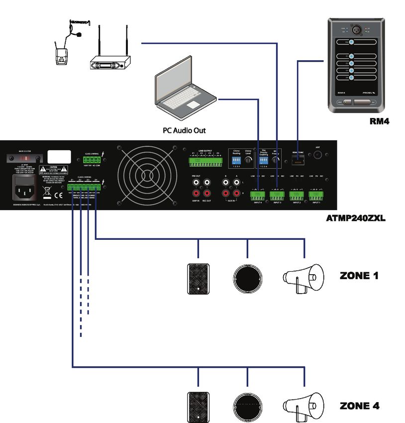
2
IMPORTANT SAFETY INSTRUCTIONS
Watch for these symbols:
 The lightning flash with arrowhead symbol within an equilateral triangle is intended to alert the user to the presence
 of uninsulated “dangerous voltage” within the product’s enclosure, that may be of sufficient magnitude to constitute
 a risk of electric shock to persons.

 The exclamation point within an equilateral triangle is intended to alert the user to the presence of important
 operating and maintenance (servicing) instructions in the literature accompanying the appliance.

1.  Read these instructions.
2.  Keep these instructions.
3.  Heed all warnings.
4.  Follow all instructions.
5.  Do not use this apparatus near water.
6.  Clean only with dry cloth.
7.  Do not block any ventilation openings. Install in accordance with the manufacturer’s instructions.
8.  Do not install near any heat sources such as radiators, heat registers, stoves, or other apparatus (including
    amplifiers) that produce heat.
9. Do not defeat the safety purpose of the polarized or grounding-type plug. A polarized plug has two blades with
    one wider than the other. A grounding-type plug has two blades and a third grounding prong. The wide blade or
    the third prong are provided for your safety. If the provided plug does not fit into your outlet, consult an
    electrician for replacement of the obsolete outlet.
10. Protect the power cord from being walked on or pinched, particularly at plugs, convenience receptacles, and the
    point where they exit from the apparatus.
11. Only use attachments/accessories specified by the manufacturer.

12.     Use only with the cart, stand, tripod, bracket, or table specified by the manufacturer, or sold with the
        apparatus. When a cart is used, use caution when moving the cart/apparatus combination to avoid injury
        from tip-over.

13. Unplug this apparatus during lightning storms or when unused for long periods of time.
14. Refer all servicing to qualified service personnel. Servicing is required when the apparatus has been damaged in
    any way, such as power supply cord or plug is damaged, liquid has been spilled or objects have fallen into the
    apparatus, the apparatus has been exposed to rain or moisture, does not operate normally, or has been dropped.
15. Warning: to reduce the risk of fire or electric shock, do not expose this apparatus to rain or moisture.
16. Do not expose this equipment to dripping or splashing and ensure that no objects filled with liquids, such as
    vases, are placed on the equipment.
17. To completely disconnect this apparatus from the ac mains, disconnect the power supply cord plug from the ac
    receptacle.
18. The mains plug of the power supply cord shall remain readily operable.
19. This apparatus contains potentially lethal voltages. To prevent electric shock or hazard, do not remove the
    chassis, input module or ac input covers. No user serviceable parts inside. Refer servicing to qualified service
    personnel.
20. This owner’s manual should be considered as a part of the product, it must accompany it at all times, and it
    needs to be delivered to the new user when this product is sold. In this way the new owner will be aware of all
    the installation, operating and safety instructions.
21. This apparatus should only be connected to a power source of type specified in this owner’s manual or on the
    unit.
22. You can clean the exterior of the unit with compressed air or with a dry cloth.
23. Don’t clean the unit using solvents like trichloroethylene, thinners, alcohol, or other volatile or flammable fluids.
24. To reduce the risk, close supervision is necessary when the product is used near children.

                                                                                                                      3
DISPOSAL OF OLD ELECTRICAL & ELECTRONIC EQUIPMENT
         This marking shown on the product or its literature, indicates that it should not be disposed with other
         household wastes at the end of its working life. To prevent possible harm to the environment or human health
         from uncontrolled waste disposal, please separate this from other types of wastes and recycle it responsibly to
         promote the sustainable reuse of material resources. Household users should contact either the retailer where
they purchased this product, or their local government office, for details of where and how they can take this item for
environmentally safe recycling. Business users should contact their supplier and check the terms and conditions of the
purchase contract. This product should not be mixed with other commercial wastes for disposal.

                  DECLARATION OF CONFORMITY
             The product is in compliance with:
             EMC Directive 2014/30/EU, LVD Directive 2014/35/EU, RoHS Directive 2011/65/EU and 2015/863/EU, WEEE
             Directive 2012/19/EU.

                                            CONDITIONS OF USE
Proel do not accept any liability for damage caused to third parties due to improper installation, use of non-original spare
parts, lack of maintenance, tampering or improper use of this product, including disregard of ascertainable and applicable
safety standards. Proel strongly recommends that this apparatus must be installed taking into consideration all current
National, Federal, State and Local regulations. The product must be installed by qualified personal. Please contact the
manufacturer for further information.

                           PACKAGING, SHIPPING AND COMPLAINT
This unit package has been submitted to ISTA 1A integrity tests. We suggest you control the unit conditions immediately
after unpacking it.
If any damage is found, immediately advise the dealer. Keep all unit packaging parts to allow inspection.
Proel is not responsible for any damage that occurs during shipment.
Products are sold “delivered ex warehouse” and shipment is at charge and risk of the buyer.
Possible damages to unit should be immediately notified to forwarder. Each complaint for manumitted package should
be done within eight days from product receipt.

                              WARRANTY AND PRODUCTS RETURN
Proel products have operating warranty and comply their specifications, as stated by manufacturer.
Proel warrants all materials, workmanship and proper operation of this product for a period of two years from the original
date of purchase. If any defects are found in the materials or workmanship or if the product fails to function properly
during the applicable warranty period, the owner should inform about these defects the dealer or the distributor,
providing receipt or invoice of date of purchase and defect detailed description. This warranty does not extend to damage
resulting from improper installation, misuse, neglect or abuse. Proel S.p.A. will verify damage on returned units, and when
the unit has been properly used and warranty is still valid, then the unit will be replaced or repaired. Proel S.p.A. is not
responsible for any "direct damage" or "indirect damage" caused by product defectiveness.

 4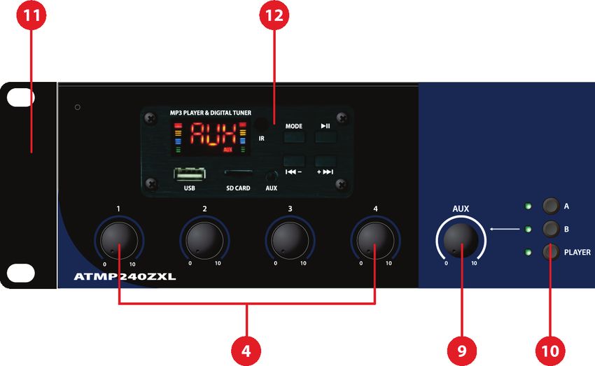
SUMMARY
IMPORTANT SAFETY INSTRUCTIONS ......................................................................................................... 3
DISPOSAL OF OLD ELECTRICAL & ELECTRONIC EQUIPMENT ....................................................................... 4
DECLARATION OF CONFORMITY ............................................................................................................... 4
CONDITIONS OF USE ................................................................................................................................ 4
PACKAGING, SHIPPING AND COMPLAINT .................................................................................................. 4
WARRANTY AND PRODUCTS RETURN ....................................................................................................... 4
INTRODUCTION ....................................................................................................................................... 7
DESCRIPTION ........................................................................................................................................... 7
MAIN FUNCTIONS .................................................................................................................................... 7
MAIN PANEL OPERATIONS ........................................................................................................................ 8
  1 POWER ......................................................................................................................................... 9
  2 MASTER ........................................................................................................................................ 9
  3 BASS AND TREBLE TONE CONTROLS ............................................................................................... 9
  4 INPUT 1 – 4 LEVEL ......................................................................................................................... 9
  5 LED INDICATOR ............................................................................................................................. 9
  6 ZONE 1-4 LEVEL SET ....................................................................................................................... 9
  7 ZONE 1-4 SELECTOR ....................................................................................................................... 9
  8 ALL ZONE SELECTOR .................................................................................................................... 10
  9 AUX LEVEL .................................................................................................................................. 10
  10    AUX SELECTOR ........................................................................................................................ 10
  11    RACK mounting ....................................................................................................................... 10
  12    MEDIA PLAYER ........................................................................................................................ 10
REAR PANEL OPERATIONS ...................................................................................................................... 10
  13    CHIME ROUTING AND LEVEL .................................................................................................... 11
  14    VOX MIC PRIORITY .................................................................................................................. 11
  15    REMOTE MIC ........................................................................................................................... 11
  16    ANT ........................................................................................................................................ 12
  17    INPUT 1-4 ................................................................................................................................ 12
  18    AUX IN A / B ............................................................................................................................ 13
  19    PRE OUT – AMP IN................................................................................................................... 13
  20    REC OUT .................................................................................................................................. 14
  21    ZONE LINE OUTPUTS................................................................................................................ 14
  22    GENERAL LOUDSPEAKER OUTPUT ............................................................................................ 14
  23    ZONE LOUDSPEAKER OUTPUT .................................................................................................. 15
  24    MAINS SELECTOR..................................................................................................................... 16
  25    FUSE holder............................................................................................................................. 17
  26    AC~ SOCKET ............................................................................................................................ 17
MEDIA PLAYER OPERATIONS................................................................................................................... 17
  27    DISPLAY................................................................................................................................... 17
  28    USB PORT................................................................................................................................ 17
  29    SD CARD.................................................................................................................................. 18
  30    AUX INPUT .............................................................................................................................. 18
  31    IR RECEIVER............................................................................................................................. 18
  32    MODE ..................................................................................................................................... 18
  33    PLAY/PAUSE ............................................................................................................................ 18
  34    PREV/VOL- .............................................................................................................................. 18
  35    NEXT/VOL+.............................................................................................................................. 18
  36    ON/OFF................................................................................................................................... 18
  37    MUTE ...................................................................................................................................... 19

                                                                                                                                                     5
38 EQ ........................................................................................................................................... 19 39 U/SD ....................................................................................................................................... 19 40 RPT ......................................................................................................................................... 19 41 0-9 .......................................................................................................................................... 19 RM-4 PAGING BASE OPERATIONS ........................................................................................................... 20 42 INPUT ..................................................................................................................................... 20 43 OUTPUT .................................................................................................................................. 20 44 POWER ................................................................................................................................... 20 45 MIC INPUT .............................................................................................................................. 21 46 MIC LEVEL ............................................................................................................................... 21 47 CHIME BUTTON ....................................................................................................................... 21 48 CHIME LEVEL ........................................................................................................................... 21 49 ALL BUTTON ............................................................................................................................ 21 50 Z1, Z2, Z3, Z4 BUTTONS............................................................................................................ 21 51 TALK BUTTON .......................................................................................................................... 21 52 SIG LED ................................................................................................................................... 21 53 CLIP LED .................................................................................................................................. 21 54 BUSY LED ................................................................................................................................ 21 SETUP EXAMPLE 1 .................................................................................................................................. 22 SETUP EXAMPLE 2 .................................................................................................................................. 23 55 TECHNICAL SPECIFICATION....................................................................................................... 24 6
INTRODUCTION
Thank you for choosing a PROEL product. Please take some time to read this manual to understand all the
features of your system and take advantage of all its performance capabilities. All PROEL products are CE
approved and designed for continuous use in professional applications.
DESCRIPTION
ATMP240ZXL is a professional mixer amplifier capable of delivering up to 240W over 4 zones, complete with
Media Player with FM radio, MP3 player on SD / USB support and Bluetooth connection.
This new mixer amplifier has been designed to meet the needs of a constantly evolving market in the most
flexible and professional way, by responding to precise operational criteria, and it is built and tested to ensure
absolute reliability for the user, even in continuous operational operation.
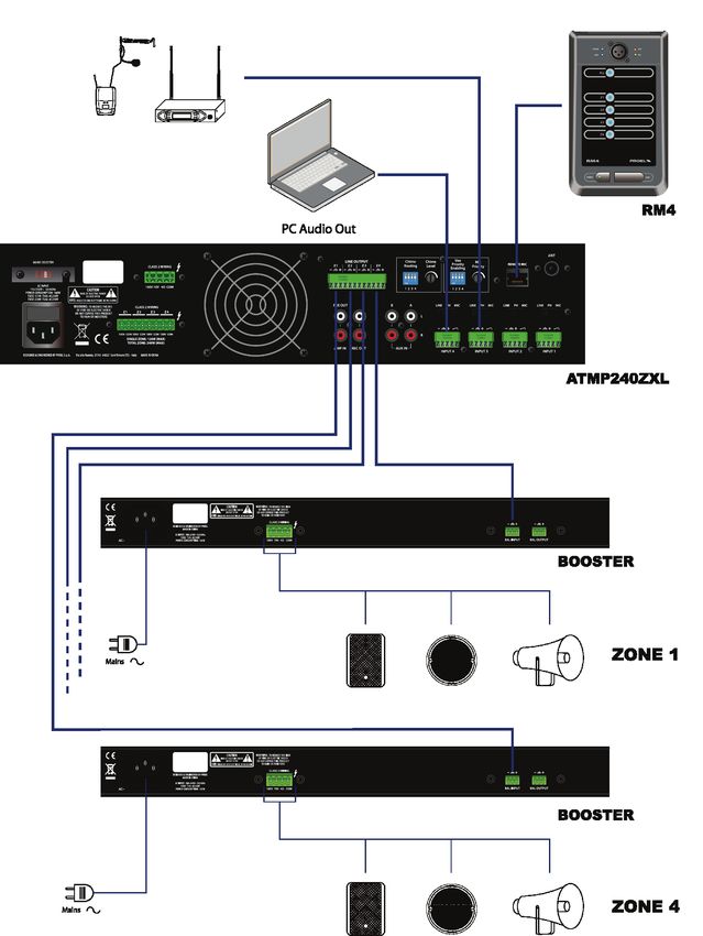
By combining up to 4 RM4 paging microphone bases with the ATMP240ZXL, it is possible to create a zone
system with call on a single zone, on groups of zones or in general on all zones. Moreover, by using the zone
outputs at line level it is possible to combine it with booster amplifiers to create a 4-zone system of even greater
power.
MAIN FUNCTIONS
• Zone paging function through dedicated PA RM4 microphone base (optional).
• Overload and short circuit protection for each speaker outputs.
• LED power indicator.
• LED audio level indicator.
• Master level control.
• Separated Level Controls for 1÷4 zones and AUX inputs.
• Bass and Treble tone adjustment.
• Media Player equipped with remote control with FM radio tuner, MP3 player on SD / USB support and
Bluetooth connection.
• N° 4 MIC / MIC Phantom 48V / LINE inputs balanced on Euroblock terminals.
• N° 3 AUX inputs switchable by front selector.
• Inputs 1 ÷ 4 with independent priority function (VOX / Contact) on the other inputs selectable by
dipswitch 1 ÷ 4.
• Main power output 4Ω / 70 / 100V on Euroblock terminal.
• N° 4 zone outputs at 100V on Euroblock terminal.
• N° 4 balanced line level zone outputs on Euroblock terminal.
• Independent CHIME function for each input (routing).
• REC OUT on RCA.
• 230 / 115 V~ 50 / 60 Hz power supply via voltage selector.
• 19" 2U rack adapters included.
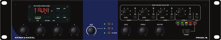
7MAIN PANEL OPERATIONS 8
1   POWER
    Main switch with LED indicator.

2   MASTER
    Main level control.

3   BASS AND TREBLE TONE CONTROLS
    The BASS control is used to adjust the low frequency band, the TREBLE control is used to adjust the high
    frequency band. The control’s range is -10 dB to +10 dB for each band. Turning the knob to the right boosts
    the corresponding frequency band, while turning to the left attenuates the band. Adjust the controls to
    obtain the best intelligibility and equalization for your audio system.

4   INPUT 1 – 4 LEVEL
    Level controls of the corresponding rear input, which can be either a microphone or a line level device
    (see point 17).

5   LED INDICATOR
    SIG: indicates the presence of an output signal.
    -10dB: indicates a normal output level.
    CLIP: indicates that the input signal is too high and the amplifier is starting to limit the signal.
    PROT: indicates that the amplifier is in protection and no signal will be reproduced from the outputs. The
    amplifier may have a shorted output or has overheated due to incorrect use.
    ON: indicates that the device is turned on.
    For a correct operation, the -10dB LED should light up often and CLIP LED should light up rarely. If the CLIP
    LED stays always on, turn down the MASTER level or the corresponding INPUT level control.

6   ZONE 1-4 LEVEL CONTROLS
    These LEVEL controls set the output volume for each corresponding zone with 6 steps. These controls
    operate as attenuators starting from the MASTER LEVEL, so position 5 corresponds to full output while
    position 0 corresponds to the zone muted. The attenuation steps are the following:
     STEP                    5              4              3              2              1               0
     Attenuation             0            -3 dB          -6 dB          -12 dB         -18 dB          - inf.
     Pwr ratio               1             1/2            1/4           1/16           1/64            inf.
    NOTE: each ZONE LEVEL control acts exclusively on the corresponding 100V ZONE OUTPUT (9).
    NOTE: when a paging call is made using the dedicated PA RM4 base, the zone volume controls will be by-
    passed and the message will be played at the volume set by the PA RM4 base and by the MASTER control.

7   ZONE 1-4 SELECTOR
    Using these keys, you can select the zone output where you want to direct audio program.
    NOTE: these controls act both on the Zone outputs at 100V (9) and on the zone outputs at line level (11).
    NOTE: when a paging call is made using the dedicated PA RM4 base, the zone selectors will be by-passed
    and the message will still reach the zone or group of zones selected on the base, temporarily silencing any
    background music.

                                                                                                                9
8 ALL ZONE SELECTOR
Press the ALL button to activate all zones at the same time.
NOTE: this control acts both on the Zone outputs at 100V (9) and on the zone outputs at line level (11).
NOTE: when a paging call is made via the dedicated PA RM4 base, the zone selectors will be by-passed and
the message will still reach the zone or group of zones selected on the base, temporarily silencing any
background music.
9 AUX LEVEL
AUX A / B or Media Player (12) input level control.
10 AUX SELECTOR
With the A, B and PLAYER buttons you can choose between the rear auxiliary inputs AUX A or AUX B (4)
or the internal Media Player (12). The corresponding LED indicates the selected input.
Note: only one input at a time can be selected.
11 RACK mounting
The equipment is supplied with 2 adapters for mounting in a 19" RACK cabinet.
12 MEDIA PLAYER
The Media Player allows to play music or other audio contents choosing between FM radio, USB pendrive,
MicroSD card or Bluetooth receiver (see below for further instructions).
REAR PANEL OPERATIONS
1013 CHIME ROUTING AND LEVEL
The Chime Routing switches enable the Chime function on the respective INPUT 1 ÷ INPUT 4 (17) inputs:
Examples:
ON – ON – ON – ON - CHIME enabled on all inputs
ON – OFF – ON – OFF - CHIME enabled on inputs 1 - 3 and disabled on inputs 2 - 4
OFF – OFF – OFF – OFF - CHIME disabled on all inputs
With the Chime function enabled on an input, when the respective dry contact closes (17 - C), the
amplifier will reproduce an attention tone from all the loudspeaker lines.
The Chime Level potentiometer set the level of the attention tone.
14 VOX MIC PRIORITY
The VOX PRIORITY ENABLING switches enable the VOX function on the respective INPUT 1 ÷ INPUT 4 (17)
inputs:
Examples:
ON – ON – ON – ON – Vox Priority enabled on all inputs
ON – OFF – ON – OFF - Vox Priority enabled on inputs 1 - 3 and disabled on inputs 2 - 4
OFF – OFF – OFF – OFF - Vox Priority disabled on all inputs
When the VOX circuit of one of the channels with VOX enabled (ON) detects the presence of an audio
signal on the respective input (17), the AUX channels (A, B, media player) and the other channels having
VOX disabled (OFF) are silenced, while all channels with VOX enabled (ON) remain active at the output.
The MIC PRIORITY knob sets the level of the signal that activates the VOX function. Turn it clockwise with
lower input signals, if turned fully counterclockwise the VOX function will be bypassed.
15 REMOTE MIC
RJ45 connector for dedicated PA RM4 microphone base for selected zones, groups of zones and general
calls.
The amplifier accepts up to a maximum of 4 PA RM4 bases connected in daisy chain configuration, with a
maximum full length of 200m of CAT5 or CAT6 net cable. See further for detailed instructions.
1116 ANT
This is a 9.5mm male antenna connector that accepts the FM antenna supplied with the unit or a 9.5mm
female TV connector wired to an external FM antenna wired with a typical coaxial 75 ohm cable.
Note: the antenna supplied is a simple wire of 140 cm length and to avoid interference it must be placed
distant from other cables and metal objects. If you experience problems with FM radio reception, we
suggest using a 75ohm coaxial cable to place the antenna in a more suitable location.
17 INPUT 1-4
These inputs can be used to connect low impedance dynamic microphones (30-600 ohm), condenser
microphones with phantom power supply and audio sources with line level signal output (e.g. radio
tuners, television receivers, media players, etc.).
a) Use a shielded cable terminated with a 3.5mm pitch Euroblock connector to make a balanced or
unbalanced connection as follows:
Connection of a Balanced line to the INPUT.
Connection of an Unbalanced line to the INPUT.
b) Use the correspondent upper switch to select the type of source connected to the input:
MIC for a dynamic microphone.
PH for a condenser microphone with phantom power.
LINE for a line level source.
c) Each input has two Euroblock terminals with 3.5mm pitch to which a "clean contact" can be connected
(clean means that it is not connected to other elements of the circuit such as GND). This contact is
usually connected to the TALK button present in the microphone bases, which also serves to activate
the microphone. When the contact is closed, two functions are activated:
12CHIME
When the contact is closed, if the CHIME dipswitch (13) of the channel is in the ON position, an
attention tone will be played by the loudspeaker system.
SILENCING THE INPUTS
When the contact is closed, the AUX input and the other inputs 1-4 that have the respective VOX
PRIORITY dipswitch (14) in the OFF position are silenced. The inputs will remain muted as long as the
clean contact remains closed.
Note: it is advisable to always use microphone bases with TALK button and clean contact, for better
management of the silencing of inputs.
Note: the clean contact will not silence the inputs that have the VOX function activated (ON). For
details on the VOX function, see point 14
WARNING
It is recommended that you set the input level to the minimum before changing the position of the input
selector, to avoid unwanted noises.
Some line level devices do not support "PH" phantom power, which could therefore cause permanent
damage to them, so it is not recommended to activate it when a line device is connected to the input.
18 AUX IN A / B
These are two RCA female connectors that accept two RCA plug from LEFT and RIGHT channels of a line
level stereo source (e.g. radio tuners, television receivers, media players, etc.). Each RCA input is wired
as follows:
Tip = + positive or "hot"
Sleeve = shield or ground
By means of these inputs is possible to use an external source instead the media player inside the
amplifier, selecting it with the front panel switches (10) and adjusting the volume with the AUX LEVEL
potentiometer (9).
19 PRE OUT – AMP IN
These are two RCA female connectors that accept two RCA plug. As standard, the AMP IN input is
connected to the PRE OUT output with a jumper.
It is possible to optimize the signal to be amplified by inserting between the two terminals an external
processing unit, typically a graphic equalizer, to optimize the spoken words intelligibility. For the
connection refer to the figure.
1320 REC OUT
These are two RCA female connectors that accept two RCA plug This is an unbalanced output that can be
used for recording or to connect other amplifiers. Please note that both left and right connectors have the
same audio content, so each one can be used also as mono output.
21 ZONE LINE OUTPUTS
The device has 4 line-level zone outputs for connecting additional zone amplifiers.
Use the balanced connection with booster amplifiers equipped with balanced input:
Use the unbalanced connection with booster amplifiers with an unbalanced input:
22 GENERAL LOUDSPEAKER OUTPUT
This is a 5.08 mm pitch Euroblock connector. This connector can accept 0.5÷2.5 mm2 / 20÷14 AWG size
cables, a Class 2 wiring is needed for fixed installation.
The device allows you to connect speakers to this general output without zone control, using constant
impedance (4Ω or 8Ω) or constant voltage (70V or 100V) speakers.
14OBSERVE ALL THESE WARNINGS:
• DO NOT CONNECT MIXED CONSTANT IMPEDANCE (4Ω or 8Ω) AND CONSTANT VOLTAGE (70V or
100V) SPEAKERS.
• CONNECTING CONSTANT IMPEDANCE (4Ω or 8Ω) LOUDSPEAKER IT IS ADVISABLE TO REDUCE AS
MUCH AS POSSIBLE THE WIRES’LENGTH AND TO INCREASE THE CABLE SECTION ACCORDING TO
THE DISTANCE COVERED.
• THE TOTAL POWER HANDLING OF CONSTANT IMPEDANCE (4Ω or 8Ω) SPEAKER MUST BE AT
LEAST 240W CONTINUOS.
• WHEN CONSTANT IMPEDANCE SPEAKERS (4Ω or 8Ω) ARE CONNECTED, IT IS FORBIDDEN TO
CONNECT CONSTANT VOLTAGE LOUDSPEAKERS ON ANY GENERAL AND ZONE OUTPUTS.
• THE TOTAL POWER OF CONSTANT VOLTAGE (70V or 100V) LOUDSPEAKERS CONNECTED MUST
NOT EXCEED 240W CONSIDERING BOTH GENERAL AND ZONE OUTPUTS.
• ALL THE LOUDSPEAKERS CONNECTED TO CONSTANT VOLTAGE OUTPUTS (70V or 100V) MUST
BE EQUIPPED WITH A TRANSFORMER HAVING AN INPUT VOLTAGE EQUAL TO THAT SUPPLIED
BY THE AMPLIFIER.
• TO AVOID THE RISK OF ELECTRIC SHOCKS, NEVER TOUCH THE AMPLIFIER OUTPUTS DURING
OPERATION.
Constant impedance line connection examples:
Constant voltage line connection examples:
23 ZONE LOUDSPEAKER OUTPUT
This is a 5.08 mm pitch Euroblock connector. This connector can accept 0.5÷2.5 mm2 / 20÷14 AWG size
cables, a Class 2 wiring is needed for fixed installation.
Connect to these separate zone outputs only constant voltage speakers at 100V.
15OBSERVE ALL THESE WARNINGS:
• DO NOT CONNECT CONSTANT IMPEDANCE SPEAKERS (4Ω or 8Ω) TO THESE OUPUTS.
• DO NOT EXCEED 120W ON EACH SINGLE ZONE LINE.
• THE TOTAL POWER OF CONSTANT VOLTAGE (70V or 100V) LOUDSPEAKER CONNECTED MUST
NOT EXCEED 240W CONSIDERING BOTH GENERAL AND ZONE OUTPUTS.
• TO AVOID THE RISK OF ELECTRIC SHOCKS, NEVER TOUCH THE AMPLIFIER OUTPUTS DURING
OPERATION.
24 MAINS SELECTOR
This switch sets the AC voltage line of the country (usually it is set by factory and isn't necessary to change
it). The 115V setting is for mains lines in the range of 100-120V~ and 230V setting is for mains lines in the
range of 220-240V~.
WARNING: an incorrect setting of AC LINE VOLTAGE could seriously damage the device!
1625 FUSE holder
Here is where the mains protection fuse is placed.
230V: T2AL AC250V.
115V: T4AL AC250V.
REPLACE THE PROTECTION FUSE ONLY WITH THE SAME TYPE.
IF, AFTER THE REPLACEMENT, THE FUSE IS BLOWN AGAIN, DO NOT TRY TO REPLACE IT AGAIN AND
CONTACT THE NEAREST PROEL SERVICE CENTER.
26 AC~ SOCKET
Here’s where you plug in your mains supply cord. You should always use the mains cord supplied with the
device. Be sure that your device is turned off before you plug the mains supply cord into an electrical
outlet.
MEDIA PLAYER OPERATIONS
27 DISPLAY
3-digit display that shows the status of the Media Player.
28 USB PORT
Slot for inserting a USB pendrive with music files in WAV, APE, FLAC, MP3 formats or standard pre-
recorded announcements.
1729 SD CARD
Slot for inserting a microSD card with music files in WAV, APE, FLAC, MP3 formats or standard pre-recorded
announcements.
30 AUX INPUT
Minijack socket for connecting an external media player, a computer, a tablet or a mobile phone.
The AUX input is selected using the MODE key, "AUX" appears on the display.
31 IR RECEIVER
It receives the signal from the remote control.
32 MODE
It changes the mode of the media Media Player between Radio (the display shows the frequency and an
FM message), Bluetooth (the display shows Bt), the USB reader (the display shows USb), the microSD
reader (the display shows SD), the input auxiliary front minijack (the display shows AUX).
For Bluetooth mode, press MODE until the "Bt" symbol flashes on the display: now it is possible to connect
the external player device (mobile phone, tablet, computer, etc.). The name "JQ-BT" will appear on the
device and, when the device is connected, the "Bt" symbol remains fixed on the display.
To unpair the amplifier it is necessary to proceed from your device: in fact, the amplifier will always
remember the connected Bluetooth devices, even after being turned back on, and it will reconnect to
them if the device is within its range (about 10m or less).
To connect another device via Bluetooth, it may be necessary to disconnect the previous one if the latter
is within its range.
33 PLAY/PAUSE
In radio mode it stores FM radio stations based on signal reception from P00 to Pnn by scanning all
frequencies from 87.5MHz to 108MHz. If you press the button again before having scanned the entire FM
spectrum, the procedure is interrupted, not memorizing all the available radio stations, therefore it is
always advisable to let the memorization procedure finish.
In USB / SD and Bt mode, it pauses or plays the songs contained in the flash memory or the connected
Bluetooth device.
34 PREV/VOL-
On the panel, if pressed and released immediately, it returns to the previous radio station or to the
previous track, if held down it decreases the volume to the minimum value U00 (note if turned off and on
again the media player restarts at the standard volume which is U10).
On the remote control, the keys are separated, one returns to the previous station, while the other
decreases the volume.
35 NEXT/VOL+
On the panel, if pressed and released, it advances to the next radio station or to the next track, if held
down it increases the volume up to the maximum value U30.
On the remote control, the keys are separated, one advances to the next station, while the other increases
the volume.
36 ON/OFF
The message OFF appears on the display and the Media Player turns off immediately.
1837 MUTE
Mutes the Media Player and the display flashes, pressing it again removes the mute and the display
returns to normal.
38 EQ
Through the settings between Eq0 and Eq5 it is possible to modify the frequency response of the Media
Player. The default equalization is Eq0 which is recalled each time the device is switched on. The
equalizations are as follows:
Eq0 = No equalization.
Eq1 = Voice Enhancement.
Eq2 = Enhancement of medium-high frequencies.
Eq3 = Enhancement of medium-low frequencies.
Eq4 = Strong high frequency enhancement.
Eq5 = Slight high frequency enhancement.
39 U/SD
In radio mode it stores FM radio stations based on signal reception from P00 to Pnn by scanning all
frequencies from 87.5MHz to 108MHz. If you press the button again before having scanned the entire FM
spectrum, the procedure is interrupted, therefore it is always advisable to let the memorization procedure
to be completed.
In USB / SD mode, if both cards are inserted, it switches playback between one card and the other.
40 RPT
In USB / SD mode, it activates the repeat which can be: ONE for the continuous repeat of the track being
played, ALL for the repeat of all the tracks contained in the USB / SD device. When the USB / SD device is
inserted, the media player restarts in ALL mode.
In the other modes it has no function.
41 0-9
In radio mode, pressing 001 to 0nn it selects the stored radio stations.
In USB / SD mode it skips to the track which, from the alphanumeric sequence determined by the file
name, results in the position of the number entered.
19RM-4 PAGING BASE OPERATIONS
RM4 is the dedicated paging microphone bases designed to be combined with the ATMP240ZXL to create
a zone system with call on a single zone, a group of zones or all zones It is possible to connect up to 4
bases in cascade, using simple RJ45 CAT5 or CAT6 cables, with a maximum total length of the CAT5/6
cables shorter than 200 meters.
42 INPUT
RJ45 connector where the CAT5 cable coming from the ATMP240ZXL or other RM4 base must be plugged
in.
43 OUTPUT
RJ45 connector where the CAT5 cable destined for the next RM4 base must be inserted.
Note: even if the input and output connections are reversed, the RM4 bases work anyway.
44 POWER
This LED, when lit, shows that the base is powered by the ATMP240XL and ready for use.
2045 MIC INPUT
This XLR connector is where to connect the gooseneck microphone supplied with the unit.
46 MIC LEVEL
This potentiometer sets the level of the gooseneck microphone. Try and set a suitable level avoiding
speaker feedback.
47 CHIME BUTTON
Press this button to enable the attention tone on the selected zones each time you press the TALK button:
the LED shows that the chime is activated.
48 CHIME LEVEL
This potentiometer sets the level of the attention tone signal.
49 ALL BUTTON
This button enables all the zones when the TALK button is pressed.
50 Z1, Z2, Z3, Z4 BUTTONS
These buttons enable the selected zones when the TALK button is pressed.
51 TALK BUTTON
Press and hold this button to make your announcement thru the PA system in the zones selected with
buttons above. Release the button when the announcement is completed.
NOTE: when the ALL/Z1/Z2/Z3/Z4 buttons are pressed once, they are automatically deselected when the
TALK button is released after the announcement is completed. If the ALL/Z1/Z2/Z3/Z4 buttons are keeping
pressed for a while, they enter in HOLD mode, so they are not deselected when the TALK button is released.
To deselect them just press any of the ALL/Z1/Z2/Z3/Z4 buttons. This feature can be useful when you need
to make multiple consecutive announcements on the same zones.
52 SIG LED
This LED shows when the gooseneck microphone signal has a correct level.
53 CLIP LED
This LED shows when an excessive signal from the base microphone is sent to the ATMP240ZXL. In this
case, you must lower the signal by operating the MIC LEVEL potentiometer (46) or by speaking away from
the gooseneck microphone.
54 BUSY LED
This LED shows when a remote RM4 base is active in the PA system: wait till the announcement from the
remote base is completed to make your announcement.
21SETUP EXAMPLE 1 22
SETUP EXAMPLE 2

                  23
55 TECHNICAL SPECIFICATION
Model: ATMP240ZXL Connectors
Total Output Power RMS 240 W
Loudspeakers Outputs 100 V / 70 V /4 Ω 5.08 mm EUROBLOCK 4 position
Zone Outputs Max Power 120 W
Zone Outputs Z1÷4 100 V 5.08 mm EUROBLOCK 2 position x4
1x REMOTE MIC RM4 (dedicate accessory) RJ45
4x LINE/PH/MIC balanced 3.5mm EUROBLOCK 5 position
Inputs
2x AUX selectable RCA (L & R)
1x MAIN IN unbalanced (link to PRE OUT) RCA
MIC: -44 dBv / 600 Ω balanced
PH: -44 dBv / 600 Ω balanced with phantom
Input Sensitivity LINE: -6 dBv / 47 kΩ balanced
AUX: 0 dBv / 10 kΩ unbalanced
MAIN IN: 0 dBv / 10 kΩ unbalanced
4x ZONE LINE OUTOUT balanced 3.5mm EUROBLOCK 12 position
Line Outputs REC OUT unbalanced RCA (L & R)
PRE OUT unbalanced (link to MAIN IN) RCA
PRE OUT: 1V / 75 Ω
Line Outputs Nominal Level REC OUT: 1V / 75 Ω
ZONE LINE OUTOUT: 1V / 75 Ω
1 MASTER VOLUME
1 TREBLE TONE
1 BASS TONE
4 MIC/LINE VOLUME
Controls 1 AUX VOLUME
4 ZONE VOLUME
4 ZONE SELECTORS
CHIME ROUTING AND LEVEL
VOX PRIORITY
Shelving +/- 10 dB @ 10 kHz
Tone Controls
Shelving +/- 10 dB @ 100 Hz
Frequency response 80 Hz ÷ 16 KHz (-3dB)
Distortion (THD) < 0.5% (@ Pnom 1KHz)
MIC: ≥70dB
S/N Ratio LINE: ≥70dB
AUX: ≥80dB
Operating temperature 0 ÷ +45°C
115 V~ ±10% 50/60Hz (select 115V) or VDE IEC C13
Power Supply
230 V~ ±10% 50/60Hz (select 230V)
Power Consumption 160 W
433 x 89 x 352 mm
Dimensions (WxHxD)
433 x 89 x 352 mm – 2U rack 19”
Weight 13.9 Kg
24IMPORTANTI ISTRUZIONI DI SICUREZZA
Fai attenzione a questi simboli:
Il simbolo del fulmine con freccia all'interno di un triangolo equilatero avverte l'utente della presenza di “voltaggio
pericoloso” all'interno del prodotto, che possono essere di intensità sufficiente a costituire un rischio di folgorazione
per le persone.
Il punto esclamativo all'interno di un triangolo equilatero avverte l'utente della presenza di importanti istruzioni
operative e di manutenzione (assistenza) nella documentazione che accompagna l'apparecchio.
1. Leggere queste istruzioni.
2. Conservare queste istruzioni.
3. Prestare attenzione a tutti gli avvertimenti.
4. Osservare tutte le istruzioni.
5. Non utilizzare questo apparecchio vicino all'acqua.
6. Pulire solo con un panno asciutto.
7. Non bloccare le aperture di ventilazione. Installare in conformità con le istruzioni del produttore.
8. Non installare vicino a fonti di calore come radiatori, termoregolatori, stufe o altri apparecchi (inclusi
amplificatori) che producono calore.
9. Non annullare i dispositivi di sicurezza della spina polarizzata o con messa a terra. Una spina polarizzata ha due
lame, una più larga dell'altra. Una spina con messa a terra ha due lame e un terzo polo di messa a terra. La lama
larga o il terzo polo sono forniti per la vostra sicurezza. Se la spina fornita non si adatta alla presa, consultare un
elettricista per la sostituzione della presa obsoleta.
10. Proteggere il cavo di alimentazione dall'essere calpestato o pizzicato, in particolare su spine, prese di corrente e
il punto in cui fuoriescono dall'apparecchio.
11. Utilizzare solo collegamenti / accessori specificati dal produttore.
12. Utilizzare solo carrelli, supporti, treppiedi, staffe o tavoli specificati dal produttore o venduti con l'apparecchio.
Quando si utilizza un carrello, prestare attenzione quando si sposta la combinazione carrello / apparecchio per
evitare lesioni dovute al ribaltamento.
13. Scollegare questo apparecchio durante i temporali o se non viene utilizzato per lunghi periodi di tempo.
14. Per tutte le riparazioni rivolgersi a personale qualificato. La manutenzione è necessaria quando l'apparecchio è
stato danneggiato in qualche modo, se il cavo o la spina di alimentazione sono danneggiati, se è stato versato del
liquido o se sono caduti oggetti nell'apparecchio, se l'apparecchio è stato esposto a pioggia o umidità, se non
funziona normalmente, o se è stato abbandonato.
15. Avvertenza: per ridurre il rischio di incendi o scosse elettriche, non esporre questo apparecchio a pioggia o
umidità.
16. Non esporre questa apparecchiatura a gocciolamenti o spruzzi e assicurarsi che nessun oggetto riempito di
liquidi, come vasi, sia posizionato sull'apparecchiatura.
17. Per scollegare completamente questo apparecchio dalla rete elettrica, scollegare la spina del cavo di
alimentazione dalla presa elettrica.
18. La spina di alimentazione del cavo di alimentazione deve sempre rimanere facilmente accessibile.
19. Questo apparato contiene tensioni potenzialmente letali. Per evitare scosse elettriche o pericoli, non rimuovere
il telaio, il modulo di ingresso o i coperchi di ingresso AC. All'interno non ci sono parti riparabili dall'utente. Per
l'assistenza rivolgersi solo a personale di assistenza qualificato.
20. Il presente manuale d'uso deve essere considerato parte del prodotto, deve accompagnarlo in ogni momento e
deve essere consegnato al nuovo utente quando questo prodotto viene venduto. In questo modo il nuovo
proprietario sarà a conoscenza di tutte le istruzioni di installazione, funzionamento e sicurezza.
21. Questo apparecchio deve essere collegato esclusivamente a una fonte di alimentazione del tipo specificato nel
presente manuale d’uso o sull'unità.
22. È possibile pulire l'esterno dell'unità con aria compressa o con un panno asciutto.
23. Non pulire l'unità utilizzando solventi come tricloroetilene, diluenti, alcool o altri liquidi volatili o infiammabili.
24. In presenza di bambini, controllare che il prodotto non rappresenti un pericolo.
25SMALTIMENTO DI VECCHIE ATTREZZATURE ELETTRICHE ED ELETTRONICHE
Il marchio riportato sul prodotto o sulla documentazione indica che il prodotto non deve essere smaltito con
altri rifiuti domestici al termine del ciclo di vita. Per evitare eventuali danni all’ambiente si invita l’utente a
separare questo prodotto da altri tipi di rifiuti e di riciclarlo in maniera responsabile per favorire il riutilizzo
sostenibile delle risorse materiali. Gli utenti domestici sono invitati a contattare il rivenditore presso il quale è
stato acquistato il prodotto o l’ufficio locale preposto per tutte le informazioni relative alla raccolta differenziata e al
riciclaggio per questo tipo di prodotto. Gli utenti aziendali sono invitati a contattare il proprio fornitore e verificare i termini
e le condizioni del contratto di acquisto. Questo prodotto non deve essere smaltito unitamente ad altri rifiuti commerciali.
DICHIARAZIONE DI CONFORMITÀ
Il prodotto è conforme a:
Direttiva EMC 2014/30/EU, Direttiva LVD 2014/35/EU, Direttiva RoHS 2011/65/EU e 2015/863/EU, Direttiva
WEEE 2012/19/EU.
CONDIZIONI DI UTILIZZO
Proel non si assume alcuna responsabilità per danni causati a terzi a causa di installazione impropria, uso di ricambi non
originali, mancanza di manutenzione, manomissione o uso improprio di questo prodotto, incluso il mancato rispetto di
standard di sicurezza accertabili e applicabili. Proel raccomanda vivamente di installare questo apparecchio tenendo conto
di tutte le normative nazionali, federali, statali e locali vigenti. Il prodotto deve essere installato da personale qualificato.
Si prega di contattare il produttore per ulteriori informazioni.
IMBALLAGGIO, TRASPORTO E RECLAMI
L’imballo è stato sottoposto a test di integrità secondo la procedura ISTA 1A. Si raccomanda di controllare il prodotto
subito dopo l’apertura dell’imballo.
Se vengono riscontrati danni informare immediatamente il rivenditore. Conservare quindi l’imballo completo per
permetterne l’ispezione.
Proel declina ogni responsabilità per danni causati dal trasporto.
Le merci sono vendute “franco nostra sede” e viaggiano sempre a rischio e pericolo del distributore.
Eventuali avarie e danni dovranno essere contestati al vettore. Ogni reclamo per imballi manomessi dovrà essere inoltrato
entro otto giorni dal ricevimento della merce.
GARANZIE E RESI
I Prodotti Proel sono provvisti della garanzia di funzionamento e di conformità alle proprie specifiche, come dichiarate dal
costruttore.
La garanzia di funzionamento è di 24 mesi dopo la data di acquisto. I difetti rilevati entro il periodo di garanzia sui prodotti
venduti, attribuibili a materiali difettosi o difetti di costruzione, devono essere tempestivamente segnalati al proprio
rivenditore o distributore, allegando evidenza scritta della data di acquisto e descrizione del tipo di difetto riscontrato.
Sono esclusi dalla garanzia difetti causati da uso improprio o manomissione. Proel S.p.A. constata tramite verifica sui resi
la difettosità dichiarata, correlata all’appropriato utilizzo, e l’effettiva validità della garanzia; provvede quindi alla
sostituzione o riparazione dei prodotti, declinando tuttavia ogni obbligo di risarcimento per danni diretti o indiretti
eventualmente derivanti dalla difettosità.
26SOMMARIO
IMPORTANTI ISTRUZIONI DI SICUREZZA .................................................................................................. 25
SMALTIMENTO DI VECCHIE ATTREZZATURE ELETTRICHE ED ELETTRONICHE .............................................. 26
DICHIARAZIONE DI CONFORMITÀ ........................................................................................................... 26
CONDIZIONI DI UTILIZZO ........................................................................................................................ 26
IMBALLAGGIO, TRASPORTO E RECLAMI .................................................................................................. 26
GARANZIE E RESI .................................................................................................................................... 26
INTRODUZIONE ...................................................................................................................................... 29
DESCRIZIONE ......................................................................................................................................... 29
FUNZIONI PRINCIPALI ............................................................................................................................. 29
1 POWER ....................................................................................................................................... 31
2 LIVELLO MASTER ......................................................................................................................... 31
3 CONTROLLI DI TONO BASS e TREBLE ............................................................................................ 31
4 LIVELLI INPUT 1 – 4...................................................................................................................... 31
5 INDICATORE LED.......................................................................................................................... 31
6 LIVELLI ZONE 1-4 ......................................................................................................................... 31
7 SELETTORI ZONE 1-4 .................................................................................................................... 31
8 ALL - SELETTORE DI TUTTE LE ZONE .............................................................................................. 32
9 LIVELLO AUX ............................................................................................................................... 32
11 Montaggio a RACK ................................................................................................................... 32
12 MODULO MULTIMEDIALE (MEDIA PLAYER)............................................................................... 32
OPERAZIONI PANNELLO POSTERIORE...................................................................................................... 32
13 CHIME ROUTING E LEVEL ......................................................................................................... 33
14 VOX PRIORITY ENABLING E MIC PRIORITY ................................................................................ 33
16 ANT ........................................................................................................................................ 34
17 INPUT 1-4 ................................................................................................................................ 34
18 AUX IN A / B ............................................................................................................................ 35
19 PRE OUT – AMP IN................................................................................................................... 35
20 REC OUT .................................................................................................................................. 36
22 USCITA ALTOPARLANTI GENERALE ............................................................................................ 36
24 SELETTORE TENSIONE DI RETE ................................................................................................. 38
25 PORTA FUSIBILE ....................................................................................................................... 39
26 PRESA AC~ .............................................................................................................................. 39
OPERAZIONI MODULO MULTIMEDIALE (MEDIA PLAYER) ......................................................................... 39
27 DISPLAY................................................................................................................................... 40
28 USB PORT................................................................................................................................ 40
29 SD CARD.................................................................................................................................. 40
30 AUX INPUT .............................................................................................................................. 40
31 IR RECEIVER............................................................................................................................. 40
32 MODE ..................................................................................................................................... 40
34 PREV/VOL- .............................................................................................................................. 40
35 NEXT/VOL+.............................................................................................................................. 41
36 ON/OFF................................................................................................................................... 41
37 MUTE ...................................................................................................................................... 41
38 EQ ........................................................................................................................................... 41
39 U/SD ....................................................................................................................................... 41
40 RPT ......................................................................................................................................... 41
41 0-9 .......................................................................................................................................... 41
OPERAZIONI BASE MICROFONICA RM-4.................................................................................................. 42
42 INPUT ..................................................................................................................................... 42
2743 OUTPUT .................................................................................................................................. 42 44 POWER ................................................................................................................................... 42 45 MIC INPUT .............................................................................................................................. 43 46 LIVELLO MIC ............................................................................................................................ 43 47 TASTO CHIME .......................................................................................................................... 43 48 LIVELLO CHIME ........................................................................................................................ 43 49 TASTO ALL ............................................................................................................................... 43 50 Z1, Z2, Z3, Z4 BUTTONS............................................................................................................ 43 51 TASTO TALK ............................................................................................................................. 43 52 LED SIG ................................................................................................................................... 43 53 LED CLIP .................................................................................................................................. 43 54 LED BUSY ................................................................................................................................ 43 ESEMPIO DI CONFIGURAZIONE 1 ............................................................................................................ 44 ESEMPIO DI CONFIGURAZIONE 2 ............................................................................................................ 45 55 SPECIFICHE TECNICHE .............................................................................................................. 46 28
You can also read