Australian Vertical Working Surface (AVWS) - Technical Implementation Plan Version 1.6
←
→
Page content transcription
If your browser does not render page correctly, please read the page content below
Australian Vertical
Working Surface (AVWS)
Technical Implementation Plan

 Version 1.6

 Intergovernmental Committee on Surveying and Mapping (ICSM)
 Geodesy Working Group (GWG)
 24 September 2021
Document History
 Version Written by Date Comment

 Jack McCubbine and 24 September 2021 Minor text edits
 1.6
 Nicholas Brown
 Jack McCubbine and 13 April 2021 Minor text edits.
 1.5
 Nicholas Brown
 Jack McCubbine and 26 February 2021 Fixed typo in link to AGQG
 1.4
 Nicholas Brown uncertainty .tif file in Section 7.
 Change in zero degree term
 discussion (see Appendix A).
 Jack McCubbine and
 1.3 10 December 2020 Addition of Appendix B to
 Nicholas Brown
 describe bias in AGQG2019
 model.
 Updated links to models in AWS in
 Jack McCubbine and Section 7.
 1.2 26 August 2020
 Nicholas Brown Refined description of AVWS and
 AGQG to describe the differences.
 Jack McCubbine and
 1.1 14 July 2020
 Nicholas Brown
 Jack McCubbine and
 1.0 16 December 2019
 Nicholas Brown

 © Commonwealth of Australia (Geoscience Australia) 2021.

With the exception of the Commonwealth Coat of Arms, and where otherwise noted, this
product is provided under a Creative Commons Attribution 4.0 International Licence.
http://creativecommons.org/licenses/by/4.0/legalcode
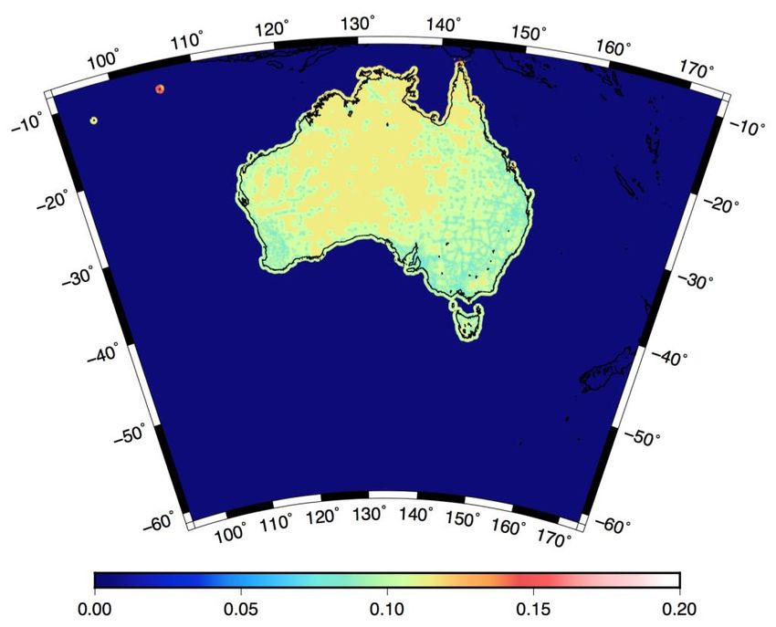
Table of contents
Document History ............................................................................................................... 2
Table of contents ................................................................................................................ 3
1. Purpose ........................................................................................................................ 4
2. Motivation for introducing AVWS.................................................................................. 4
3. Height Fundamentals .................................................................................................... 4
 3.1 Physical Height Datums ................................................................................................ 5
 3.2 Height Systems and Height Datums ............................................................................. 6
 3.3 Gravity Potential ........................................................................................................... 7
4. Geoid ........................................................................................................................... 7
 4.1 Developing a geoid model ............................................................................................ 8
 4.2 Orthometric Height System .......................................................................................... 9
5. Quasigeoid ..................................................................................................................10
 5.1 Developing a quasigeoid model ................................................................................. 12
 5.2 Normal Height System ................................................................................................ 12
 5.3 Normal-Orthometric Height System .......................................................................... 12
6. Australian Vertical Working Surface .............................................................................13
 6.1 AVWS Purpose ............................................................................................................ 13
 6.2 AVWS Definition ......................................................................................................... 13
 6.3 Issues with AHD .......................................................................................................... 14
 6.4 Benefits of AVWS ........................................................................................................ 15
 6.5 Computing derived AHD and AVWS heights from GNSS ............................................ 16
 6.6 Computing AVWS heights from levelling.................................................................... 17
 6.7 Computing AVWS height uncertainties ...................................................................... 18
7. Access to AGQG models ...............................................................................................19
Appendix A - The zero degree term.....................................................................................20
Appendix B – AGQG version control ...................................................................................22
References .........................................................................................................................23
1. Purpose The purpose of this document is to provide a publicly accessible resource of: information explaining the need for the Australian Vertical Working Surface (AVWS); definition of AVWS and its relationship to the Australian Height Datum (AHD); and information, tools, products and services to enable people to access AVWS. The document addresses many of the complex geodetic and technical issues associated with the implementation of a vertical reference surface and is therefore intended for those with expertise in geodesy or the geospatial industry. For more foundational information please see the ICSM website (https://www.icsm.gov.au/australian-vertical-working-surface). 2. Motivation for introducing AVWS The Australian Government has committed $225m to Geoscience Australia to implement the Positioning Australia program to provide accurate and reliable positioning to everyone. In anticipation for the growing use and reliance on positioning technology, the ICSM Geodesy Working Group is leading the upgrade of a number of elements of Australia’s Geospatial Reference System including the introduction of AVWS. The AVWS is the vertical reference for heights, realised by subtracting an Australian Gravimetric Quasigeoid (AGQG) model value from GDA2020 ellipsoidal heights. The AGQG model provides the height difference between the ellipsoid and the AVWS. It differs from AUSGeoid2020, which provides the offset between the ellipsoid and Australian Height Datum (AHD), by between -1 to 1 m throughout Australia. The AVWS is not replacing AHD, but instead is an alternative reference for heights for those who seek accuracies better than 10 cm. A recent user requirements study (Brown et al., 2019a; Brown et al., 2019b) found that AHD is not capable of meeting some user requirements; predominantly when working over distances greater than 10 km. This is predominantly due to localised errors and distortions in the AHD. When deriving AHD heights from GNSS and AUSGeoid, users are able to achieve accuracy of 6-13 cm. The alternative, AGQG, is accurate to 4-8 cm and will improve over time as data is added (predominantly from airborne gravity). 3. Height Fundamentals Height determination in Australia requires a level of care due to the number and types of datum, their relationships to one another and how heights are referred, as shown in Figure 1, including: Ellipsoid: Simplified mathematical representation of the Earth often used as a reference surface for positioning, navigation, map projections and geodetic calculations. Ellipsoidal heights ℎ are the distance between the ellipsoid and point of interest measured along a straight line perpendicular to the ellipsoid. Geoid: Surface of equal gravity potential (or equipotential) that closely approximates mean sea level. Heights with respect to the geoid are known as orthometric heights and are the curved line distance between the geoid and point of interest measured along the plumbline.
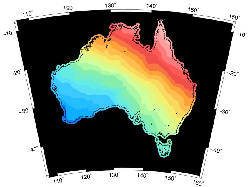
Telluroid: A theoretical surface that looks like the Earth surface except that it is
 displaced by the quasigeoidal height. The normal potential gravity is equal to the true
 gravity potential on the Earth’s surface.
 Quasigeoid: Non-equipotential surface of the Earth’s gravity field closely aligned to the
 geoid with differences up to about 3.4 m in the Himalayas (Rapp, 1997) and 0.15 m in
 Australia (Featherstone and Kirby, 1998). Heights with respect to the quasigeoid are
 known as normal heights * and are the curved line distance between the quasigeoid
 and point of interest measured along the plumbline.
 Mean Sea Level: Mean Sea Level (MSL) is an observed tidal datum and is used as the
 conventional reference surface to which heights on the terrain (e.g. contours, heights
 of mountains, flood plains, etc.) and other tidal datums are related.
 Mean Sea Surface: Mean Sea Surface (MSS) is the sum of the geoid (closely
 approximated by MSL) and Mean Dynamic Topography (MDT) which describes the
 thermodynamic motion of the oceans.

Figure 1: Heights can be observed or derived with respect to an ellipsoid, geoid or quasigeoid surface.

3.1 Physical Height Datums
Fluid will flow according to gravity potential, making the geoid (a surface with equal gravity
potential at every point) a useful datum for heights. An ellipsoid does not have equal gravity
potential. In fact, across Australia, the difference between the geoid and the ellipsoid is
between -30 and +80 m (Figure 2). For this reason, ellipsoidal heights observed using Global
Navigation Satellite Systems (GNSS) often need to be converted to physical heights (a height
with respect to the Earth’s gravity potential) using a model of the geoid or quasigeoid.
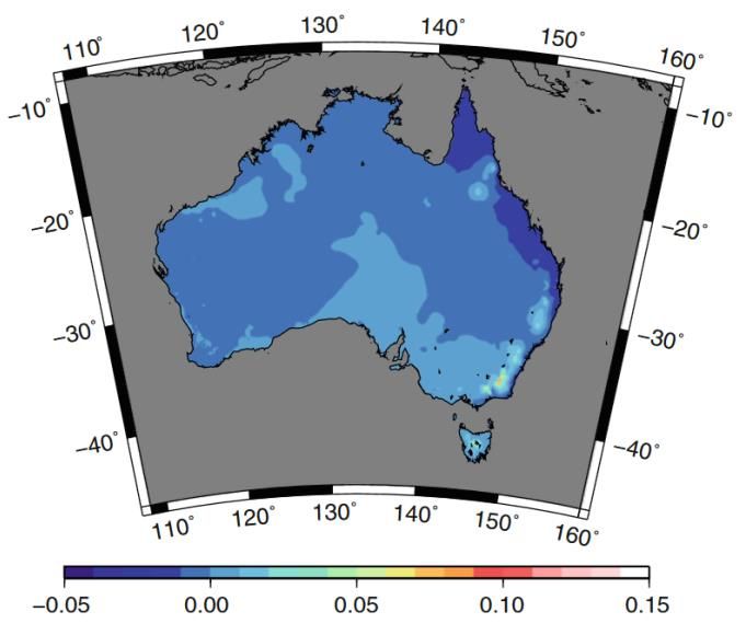
Figure 2: The difference between the AUSGeoid2020 geoid model (Brown et. al 2018) and the GRS80 ellipsoid is between -30 and +80 m across Australia. Scale in m. 3.2 Height Systems and Height Datums A height system is a coordinate system used to define the height of a point above or below a reference surface. Its definition varies according to the reference surface chosen (e.g. geoid) the path along which the height is measured (e.g. plumbline). A height datum is the practical realisation of a height system (e.g. Australian Height Datum). A height system can have many realisations (datums) as new theories, computational process and data become available. Generally, each new height datum is a better (more accurate, reliable, robust and fit for purpose) realisation of the height system. Although there is only one legally defined national height datum, AHD, there are many other height datums used in Australia (mining, rail, road authorities, marine etc.). It is therefore important to clearly define the following elements of a height datum: the height system, including a reference ellipsoid and theoretically true equipotential surface (e.g. 0 = 62,636,855.69 2 −2); and the information used in an attempt to physically realise the height system. In the case of AHD, this information includes: o Mean Sea Level (MSL) observations at 32 tide gauges around Australia; and
o Over 200,000 km of levelling used to transfer MSL heights throughout
 Australia.

3.3 Gravity Potential
The gravity potential energy at a location is equal to the work (energy transferred) per unit mass
needed to move an object from one point to another point.

The geopotential number is the basis of all height systems in physical geodesy. A
geopotential number is the difference in gravity potential energy between a point (e.g on the
Earth’s surface) and potential on the reference surface 0 (e.g. the geoid),
 = − 0
The negative of the geopotential number ( 2 / 2 ), divided by some value of gravity ( / 2 )
yields a unit of length ( ).

4. Geoid
There are an infinite number of surfaces of equal gravity potential radiating out from the centre
of mass of the Earth to outer space. The geoid is the surface of equal gravity potential which is
the best fit to mean sea level and is denoted by 0 (units 2 −2 ) (Figure 3).

Figure 3: The geoid is the surface of equal gravity potential which is the best fit to mean sea level and is denoted by
 0 .

Heights with respect to the geoid are called orthometric heights . To approximately compute
physical heights from GNSS, the geometric distance between the ellipsoid and the geoid is known
as the ‘geoid undulation’, , needs to be subtracted from the ellipsoidal height ℎ (Figure 4).

 ≈ℎ−
Figure 4: The geometric distance between the ellipsoid and the geoid is the geoid undulation, N.

There are a wide range of geoid models which have been developed to enable the conversion of
geometric ellipsoidal heights to physical heights including global gravity models such as the Earth
Geopotential Model 2008 (EGM2008). EGM2008 has an absolute accuracy of about 20 cm (Yi
and Rummel, 2013). In cases where a more accurate datum for physical heights is required, some
countries have developed national or local geoid models which use a global gravity model, and
augment it with local data such as terrestrial and airborne gravity data.

4.1 Developing a geoid model
The disturbing potential, is the difference between the Earth’s gravity potential field and
the gravity potential field of the ellipsoid .

 = −

When is known on the surface of the geoid, the geometric separation / geoid undulation ( )
between the geoid surface and the ellipsoid is given by;

 =

where is the normal gravity (i.e. the gradient of the ellipsoidal potential) evaluated on the
surface of the ellipsoid.

The potential , and therefore the disturbing potential , cannot be measured directly. But the

gradient of the potential, (i.e. the familiar gravity value ≈ 9.8 −2 ) can be measured using
gravimeters.

We define the gravity anomaly Δ as the difference between measure gravity on the geoid
surface and normal gravity on the ellipsoid surface (Figure 5).
Figure 5: Gravity anomalies over the Australian continent.

When the gravity anomalies are known on the geoid over the surface of the whole Earth, there
is a mathematical relationship between them and the disturbing potential. This is known as
Stokes integral (Moritz, 1980).

 = ∫ ( )

In practice, only long wavelengths of Δ are available over the whole Earth. This means only long
wavelength models of the disturbing potential can be determined globally. High resolution geoid
models are developed locally via the remove compute restore technique, where higher
resolution gravity data are available. i.e.

 ̂ +
 = ∫ (Δ − Δ ) ( )
 ̂

Where Δ and and gravity anomalies and geoid undulations from a long wavelength
global model, ( )̂ is a modified form of ( ) where long wavelengths have been removed, ̂
is the local region the higher resolution gravity data are available.

4.2 Orthometric Height System
The orthometric height system is compatible with a geoid model. An orthometric height is the
curved line distance between the geoid and point of interest measured along the plumbline and
computed by,

 = / ̅
where the geopotential number is divided by the integral mean of gravity taken along the
plumbline ̅ .

 NOTE 1: In the case of an orthometric height system, computation of the
 geopotential number requires gravity observations.
 NOTE 2: Given that orthometric heights require information of the Earth’s gravity
 acceleration along the length of the plumbline through the topography, it is
 impossible to realise in practice.
 NOTE 3: Helmert orthometric height systems use an approximation of the Earth’s
 gravity field and are not truly orthometric height systems.

5. Quasigeoid
Recognising that evaluating (the potential at point p) on the geoid is practically impossible to
do, Molodensky (1945) introduced an alternative theoretical surface called the quasigeoid. For
the determination of the quasigeoid all the computations are done, not on the geoid surface but,
on the surface of the Earth. Molodensky’s approach deals only with the external field and only
needs to know the geometry of the external field. The normal gravity is evaluated on the surface
of the telluroid.

 Telluroid: A theoretical surface where the normal potential gravity is equal to the true
 gravity potential on the Earth’s surface i.e. Up3 = Wp4 and on the same plumb line; and
 looks like the Earth surface except that it is displaced from the Earth surface by the
 quasigeoidal height (Figure 6).
Figure 6: The telluroid is a theoretical surface where the normal potential gravity is equal to the gravity potential of
the Earth on the Earth’s surface i.e. 3 = 4 .

Offshore, where there is no topography, the quasigeoid agrees with the geoid. The quasigeoid
can, in theory, be determined exactly (i.e. without any approximations). It provides the reference
surface for normal heights ∗ which can be determined from levelling and gravity observations,
or derived normal heights from GNSS and a quasigeoid model. Onshore, it differs from the geoid
by 1-2 cm in flat terrain up to 10 cm in steep topography (Figure 7).

 Figure 7: Differences between Helmet Orthometric (from geoid) and Normal Heights (from quasigeoid) (in m) over
 Australia from Filmer et al. (2010).

To compute normal heights from GNSS, the geometric distance between the ellipsoid and the
quasigeoid is known as the height anomaly needs to be subtracted from the ellipsoidal height
ℎ.

 ∗ = ℎ −

In the same way that a geoid model gives geoid undulation at any point, quasigeoid models
gives height anomalies at any point. The normal height of a point on the topographical surface
is defined as the height of the corresponding point on the telluroid above the reference ellipsoid,
measured along the normal plumbline. However, normal heights may equivalently be seen as
heights of the topographical surface above the quasigeoid, also measured along the normal
plumbline.
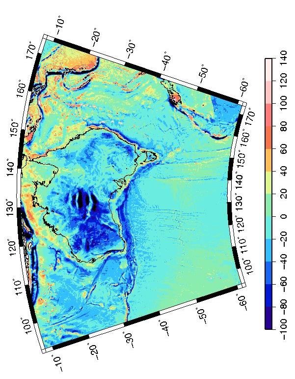
5.1 Developing a quasigeoid model
On the Earth’s surface the disturbing potential is given by,

 4 = 4 − 3 +

and so
 4
 = .

Here, is the normal gravity, evaluated on the telluroid.

5.2 Normal Height System
The normal height system was proposed in 1954 by Molodensky et al. (1962) to overcome the
problem in orthometric heights of having to determine the mean value of gravity along the
plumbline. The normal height ∗ is the distance between the quasigeoid and the point of
interest measured along the curved normal and computed by,
 ∗ = / ̅
 ̅ along the plumbline.
where the geopotential number is divided by average normal gravity

5.3 Normal-Orthometric Height System
The normal-orthometric height is distance between the quasigeoid and the point of
interest measured along the curved normal gravity plumbline and computed by,
 = / ̅
In contrast to orthometric and normal height systems, which require gravity observations to be
taken along the levelling traverse in order to derive the geopotential numbers (or normal or
orthometric corrections), geopotential numbers, , are replaced by differences in normal
potential (known as normal-geopotential or spheropotential numbers) and gravity is
replaced by normal gravity (integral mean value of normal gravity taken along the normal
plumbline between the quasigeoid and point of interest) (Featherstone and Kuhn, 2006).

The difference between normal heights and normal-orthometric heights is due to the gravity
correction applied to levelling data. Normal heights require a location specific gravity value,
whereas, normal-orthometric heights are derived using a gravity value based on the normal
gravity field (Rapp, 1961). The difference between these two height systems is shown in Figure
8.
Figure 8: The difference between normal and normal-orthometric heights over Australia (from Filmer et al, 2010) in metres. Stats: [min: -2.4 cm; max: 17.7 cm; std: 1.2 cm]. 6. Australian Vertical Working Surface 6.1 AVWS Purpose The purpose of the Australian Vertical Working Surface (AVWS) is to provide a reference surface for heights which: works seamlessly onshore and offshore; is directly compatible with Global Navigation Satellite Systems (GNSS); is continuously improved over time; and is more accurate because it does not suffer from biases and distortions in the Australian Height Datum (AHD). 6.2 AVWS Definition The Australian Gravimetric Quasigeoid model can be used to transform ellipsoidal ∗ heights ℎ (from GNSS observations) into AVWS heights .
∗ = ℎ − The AGQG is defined on a 1 arc minute grid from 8∘ (S) to 61∘ (S) and 93∘ (E) to 174∘ (E). The latest AGQG model (AGQG2017) was determined from (approx. 1.8 million) onshore gravity values provided in the Australian National Gravity Database, offshore satellite altimetry derived gravity anomaly values from Sandwell et al. (2014), the global gravity model (EGM2008), and the national digital elevation model DEMH1s. A detailed description of the procedure used to create the model is given in Featherstone et al. (2018). 6.3 Issues with AHD The Australian Height Datum (AHD) is known to have a number of biases and distortions which mean GNSS users are only capable of deriving AHD heights with an accuracy of 6-13 cm across Australia. These biases and distortions are attributable to: The ocean’s time-mean dynamic topography (MDT). Short tide gauge observation periods (~30 days). The zero reference of the AHD (MSL at 32 tide gauges) is not coincident with an equipotential surface (e.g. the geoid). This largely manifest in a north-south tilt of ~0.7 m in the AHD relative to the geoid across the continent. Local and regional distortions due to systematic and gross errors in the Australian National Levelling Network (ANLN) that are propagated through the national network adjustments. These non-gravimetric artefacts are inconsistent over large distances (e.g. greater than 10 km) and means that GNSS users are only capable of deriving AHD heights with accuracy of 6-13 cm across Australia. Uncertainty in the national height datum of this magnitude makes AHD inappropriate for some applications that require a more accurate reference surface. In response to this Geoscience Australia led a user requirements study with FrontierSI to investigate current and future requirements for physical height determination and transfer in Australia (Brown et al. 2019a; Brown et al. 2019b; McCubbine et al. 2019). In addition to the aforementioned deficiencies, feedback from the user requirements study included commentary on the lack of levelling benchmarks. In some regions, physical monuments have never been established or have been destroyed. In these areas levelling users are unable to tie into the datum easily, and for GNSS users the geometric component of the AUSGeoid2020 model is not adequate. Furthermore, users commented on difficulties combining data in the littoral zone. AHD is only an onshore datum. This is problematic for datasets which cover on and offshore regions (e.g. bathymetric and topographic elevation models). Overall, the results of the study indicated that AHD is still fit for purpose for tasks over short distances (less than about 10 km) for projects such as cadastral, civil engineering, construction and mining while users are less satisfied when working over larger areas (greater than about 10 km) for environmental studies (e.g. flood, storm modelling), LiDAR surveys, geodesy, hydrography which prompted the development of AVWS.
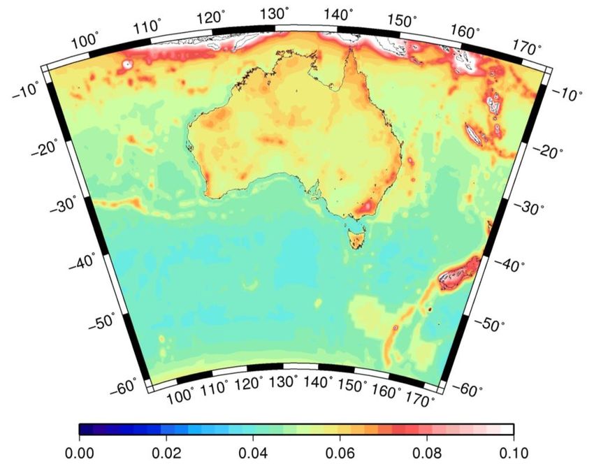
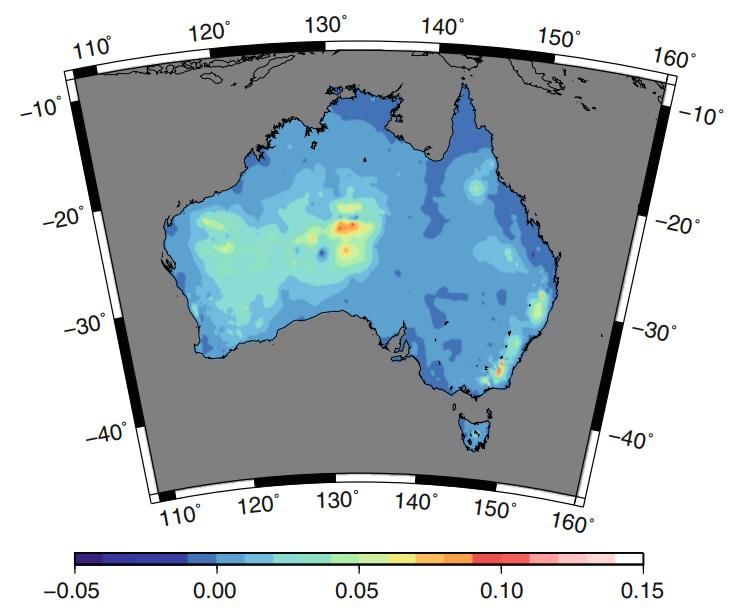
6.4 Benefits of AVWS In comparison to AHD, AVWS is: Internally consistent, being defined solely from gravity field measurements i.e. it is not contaminated with non-gravimetric artefacts due to mean dynamic topography and local distortions in levelling networks. Not reliant upon benchmark heights. Defined seamlessly on and offshore. For these reasons it better meets the needs identified during the user requirements study to establish or transfer accurate heights over longer (>10 km) distances. Additionally, the AGQG model is provided with a corresponding map of uncertainty values formally propagated from the raw data sources through each stage of the computation (Featherstone et al., 2018). The uncertainty in the AGQG2017 model is 4-8 cm across mainland Australia. AUSGeoid2020 on the other hand has uncertainty of 6-13 cm (Figure 9).
Figure 9: (top) One standard deviation of AGQG2017 uncertainty. Units in metres. (bottom) One standard deviation
of AUSGeoid2020 uncertainty. Units in metres from Brown et al. (2018).

The improvement in accuracy over larger distances addresses one of the biggest concerns from
the users who have noticed the quality of their data (e.g. LiDAR) was starting to become more
accurate than the datum (AHD) when they applied AUSGeoid. Geoscience Australia will be
working with all the states and territories to continuously improve the AGQG model as new
gravity data is included and modelling techniques are refined.

6.5 Computing derived AHD and AVWS heights from GNSS
 ∗
AVWS heights can be computed by subtracting the AGQG model value from
GNSS ellipsoidal height observation.
 ∗
 = ℎ −

Derived AHD heights can be computed by subtracting the corresponding AUSGeoid model
value from GNSS ellipsoidal height observation (Figure 10).

 = ℎ −
 NOTE: If you have GDA94 ellipsoid heights, use AUSGeoid09.

 NOTE: If you have GDA2020 ellipsoidal heights, use AUSGeoid2020.
Figure 10: The AUSGeoid model (dark blue) enables users to convert ellipsoidal heights (green) to derived AHD heights
(light blue). The AGQG model (dark purple) enables users to convert ellipsoidal heights (green) to AVWS heights (light
purple).

6.6 Computing AVWS heights from levelling
To determine AVWS heights via levelling, a reference point/s must first be established
from GNSS height/s ℎ and AGQG model value/s.
 ∗
 = ℎ −

Heights can then be transferred via levelling. Formally, normal corrections should be applied to
the relative levelling heights. The normal correction applied to levelling height differences at
points A and B, is given by,
 − 0 ̅ − 0
 ̅ − 0

 = ∑ 0
 + 0
 − 0

where are surface gravity measurements between and and ̅ and ̅ are the average
normal gravity along the curved normal plumbline, between the ellipsoid and telluroid. In
practice this requirement can generally be neglected at the cost of introducing a small amount
of error (c.f. Filmer et al. (2010)).

For example: Suppose we have two points A at (φ=-24.65, λ=153.16667) and B at (φ=-24.6167,
λ=115.3333) with uncorrected normal heights = 180.8741 and = 181.1234.

The differential height of the points is = 0.2493 . The average gravity between the points
is =9.7885607011. The average normal gravity of point A is = 9.7890357117 and the
average normal gravity of point B is = 9.7890125308. With 0 = 9.8061992115 the normal
gravity at 45∘ degrees latitude, the normal correction applied to the differential height between
A and B is
− 0 ̅ − 0 ̅ − 0 = + − 0 0 0 9.7885607011 − 9.8061992115 = 0.2493 9.8061992115 9.7890357117 − 9.8061992115 + × 180.8741 9.8061992115 9.7890357117 − 9.8061992115 − × 181.1234 = 0.0004 m 9.8061992115 6.7 Computing AVWS height uncertainties Uncertainty values of heights above the AGQG, ( ) should be modelled as the square root of the sum of Global Navigation Satellite System (GNSS) ellipsoidal height uncertainties squared, (ℎ)2 , output from GNSS processing software and AGQG uncertainty value, 2 ( ) interpolated from the AGQG uncertainty model (Featherstone et al., 2018), details in Section 7. 2 ( ) = √ (ℎ)2 + ( ) For example: We have a GPS observation at [φ=-23.6701, λ=133.8855] with ellipsoidal height ℎ = 603.244 m, the standard deviation of the ellipsoidal heights after post processing is (ℎ) = 0.0035 . The AGQG value at the respective latitude and longitude is = 15.201 and has uncertainty value ( ) = 0.06. The AVWS height is then given by = ℎ − = 588.043 2 The AVWS height uncertainty is given by ( ) = √ (ℎ)2 + ( ) = √0.062 + 0.0042 = ±0.06 i.e. the AVWS height at our point is = 588.043 ± 0.06
7. Access to AGQG models The AGQG model, and corresponding uncertainty model, is available from the links below in a range of formats: TIF, GSB (binary) and Windows ASCII. To download the files, click on the link, or paste the link in an internet browser and hit Enter. The file should download automatically. Geoscience Australia has also developed an online tool with batch processing capabilities to determine AVWS heights from GNSS observations (and vice versa) with 1 uncertainties. o Available at: https://geodesyapps.ga.gov.au/avws AGQG TIF Ellipsoid-AVWS https://s3-ap-southeast- separation 2.amazonaws.com/geoid/AGQG/AGQG_20201120.tif AGQG TIF Ellipsoid-AVWS https://s3-ap-southeast- separation 2.amazonaws.com/geoid/AGQG/AGQG_uncertainty_20201120.tif uncertainty (1 sigma) AGQG Binary Ellipsoid-AVWS https://s3-ap-southeast- separation 2.amazonaws.com/geoid/AGQG/AGQG_20201120.gsb AGQG Binary Ellipsoid-AVWS https://s3-ap-southeast- separation 2.amazonaws.com/geoid/AGQG/AGQG_uncertainty_20201120.gsb uncertainty (1 sigma) AGQG Winter Ellipsoid-AVWS https://s3-ap-southeast-2.amazonaws.com/geoid/AGQG/AGQG ASCII separation _20201120_Win.dat AGQG Winter Ellipsoid-AVWS https://s3-ap-southeast- ASCII separation 2.amazonaws.com/geoid/AGQG/AGQG_uncertainty_20201120_Win.dat uncertainty (1 sigma)
Appendix A - The zero degree term
The Earth’s gravity potential field is closely approximated by that of an ellipsoid with its own
gravity potential field .

On the surface of the geoid the value of the Earth’s potential is constant, = 0 (see Section
4).

When modelling the Earth’s gravity field with a spherical harmonic model (SHM, e.g.
EGM2008), a reference ellipsoid is chosen to (i) have a mass that is equal to that of the Earth
(which is equal to the mass of the EGM2008 SHM) and (ii) ensure that on the surface of the
ellipsoid the ellipsoidal gravity potential is equal to the Earth’s gravity potential on the geoid
i.e. = 0 = 0 . The surface of the geoid is described relative to the surface of the reference
ellipsoid. With these particular specifications for the reference ellipsoid, the ellipsoid-geoid
separation is zero on average, in a global sense.

However, the choice of and 0 used to define the reference ellipsoid for a SHM can differ to
other ellipsoids commonly used in positioning. For example, the SHM for EGM2008 uses a Mean
Earth Ellipsoid (MEE), not GRS80. Therefore ≠ 80 and 0 ≠ 0 80.

The different values of and 0 for EGM2008 and GRS80 cause a constant bias which effects
the scale of the reference ellipsoid’s gravity field. This constant bias is the amount which needs
to be added or subtracted to EGM2008 SHM ellipsoid-geoid separation values to align them
with GRS80.

This bias is known as “the zero degree term”, here denoted .

The zero degree term can be approximated, from the generalised Bruns equation,
 − 0 0 − 0
 = −

where:

 – Newton’s Gravitational constant G, multiplied by the mass of the Earth M, as
 chosen for the production of the SHM.
 0 – Newton’s Gravitational constant G, multiplied by the mass of the reference
 ellipsoid 0 .
 – Normal (i.e. due to the ellipsoid) gravity
 – Radius of computation point
 0 – Earth potential gravity value on the geoid surface from SHM
 0 – Normal (i.e. due to the ellipsoid) gravity potential on the ellipsoid

Long wavelengths of AGQG models are based on the EGM2008 SHM. To account for the bias
between EGM2008 and GRS80 it is necessary to apply the zero degree term bias to AGQG. This
enables the accurate conversion of ellipsoidal heights based on GRS80 (e.g. GDA2020 and
ATRF2014) to AVWS heights.

The following constants were used to compute this value.

 ELLIPSOID PARAM VALUE UNIT SOURCE/COMMENT
 EGM2008 3.9860044E+14 m3s-2 Ince, 2011
 0 62636855.69 m2 s-2
GRS80 0 3.9860050E+14 m3s-2 Moritz, 1980b
 0 62636860.85 m2 s-2
 9.797644656 ms-1 Mean gravity over the surface of
 the GRS80 ellipsoid
 6378137 m

This yields a zero degree term of -0.41 m.

The software used to create AGQG applies the zero degree term (-0.41 m) to all EGM2008
ellipsoid-geoid separations 2008 (which were previously referenced to the EGM2008 MEE)
to convert them to AGQG ellipsoid-geoid separations .

Figure A1 – The zero degree term must be applied to convert the EGM2008 ellipsoid-geoid separations to GRS80
ellipsoid-geoid separations.
Appendix B – AGQG version control B.1 AGQG_20201120 model This is the current version of the AGQG model The zero degree term offset between AGQG_20201120 and GRS80 is 0 m. This means there AGQG_20201120 will work seamlessly with GDA2020 and ATRF2014. B.2 AGQG_20191107 model The zero degree term offset between AGQG_20201120 and AGQG_20191107 is 0.93 m. Heights above AGQG_20191107 will be 0.93 m larger than heights above AGQG_20201120. For the 20191107 release of AGQG (AGQG_20191107) Geoscience Australia applied a -1.34 m zero degree term instead of -0.41 m. This error is due to Geoscience Australia accounting for the bias between EGM2008 and GRS80 in two steps. First, accounting for the 0.41 m offset between EGM2008 and WGS84, then applying a 0.93 m offset between GRS80 and WGS84 (From ICGEM FAQ Q17). The second correction only accounts for the mass difference between WGS84 and GRS80 but not for the difference between the GRS80 and WGS84 0 values (i.e. the second term of Eq. A1). The proper inclusion of the second term makes the GRS80 to WGS84 bias almost equal to zero. For this reason there is a 0.93 m bias between AGQG_20201120 and AGQG_20191107. For those who have used the AGQG_20191107 model, the relative heights between points will be unaffected. However, to ensure alignment with future AGQG models (including AGQG_20201120), it is recommended that users identify the original ellipsoidal height data (with respect to GDA2020), and convert the data to AVWS heights using the AGQG_20201120 model. B.3 AGQG_2017 model The zero degree term offset between AGQG_20201120 and AGQG_2017 is -0.41 m. Heights above AGQG_2017 will be 0.41 m smaller than heights above AGQG_20201120. For the 2017 release of AGQG (Featherstone et al. 2018), no zero degree term was applied. For this reason the AGQG2017 model is aligned with the EGM2008 ellipsoid so there is a -0.41 m bias between AGQG_20201120 and AGQG_2017. For those who have used the AGQG_2017 model, the relative heights between points will be unaffected. However, to ensure alignment with future AGQG models (including AGQG_20201120), it is recommended that users identify the original ellipsoidal height data (with respect to GDA2020), and convert the data to AVWS heights using the AGQG_20201120 model.
References
Brown, N., J. McCubbine, W. Featherstone, N. Gowans, A. Woods, and I. Baran (2018),
AUSGeoid2020 combined gravimetric–geometric model: location-specific uncertainties and
baseline-length-dependent error decorrelation, Journal of Geodesy, 92(12), 1457-1465.

Brown, N., J. McCubbine, W. Featherstone (2019a), Next Generation Height Reference Frame:
Part 1/3 Executive Summary, https://frontiersi.com.au/wp-content/uploads/2019/04/1-of-3-
FrontierSI-P1.29-Executive-Summary.pdf.

Brown, N., N. Bollard, J. McCubbine, W. Featherstone, (2019b), Next Generation Height
Reference Frame: Part 2/3 User Requirements, https://frontiersi.com.au/wp-
content/uploads/2019/04/2-of-3-FrontierSI-P1.29-User-Requirements.pdf.

Featherstone, W., and Kirby, J (1998), Estimates of the separation between the geoid and the
quasigeoid over Australia. Geomatics Research Australasia. 68: pp. 79-90.

Featherstone, W., and M., Kuhn (2006), Height Systems and Vertical Datums: a Review in the
Australian Context. Journal of Spatial Science. 51 (1): pp. 21-41.

Featherstone, J. McCubbine, N. Brown, S. Claessens, M. Filmer, and J. Kirby (2018), The first
Australian gravimetric quasigeoid model with location-specific uncertainty estimates, Journal of
Geodesy, 92(2), 149-168.

Filmer, M., W. Featherstone, and M. Kuhn (2010), The effect of EGM2008-based normal,
normal-orthometric and Helmert orthometric height systems on the Australian levelling
network, Journal of Geodesy, 84(8), 501-513.

ICGEM FAQ: http://icgem.gfz-potsdam.de/faq . Last accessed Dec 2020.

Ince, E.S., 2011. Geoid investigations for the new vertical datum in Canada. UCGE Reports,
(20344).

McCubbine, J., N. Brown, W. Featherstone, M. Filmer, N. Gowans, (2019), Next Generation
Height Reference Frame: Part 3/3 Technical Requirements, https://frontiersi.com.au/wp-
content/uploads/2019/05/3-of-3-FrontierSI-P1.29-Technical-Requirements.pdf.

Molodensky, M. S., V. F., Eremeev, and M. I., Yurkina, (1962), Methods for study of the external
gravitational field and figure of the earth, Transl. from Russian (1960) Israel Program for
Scientific Transl., Jerusalem.

Moritz, H. (1980), Advanced physical geodesy, Advances in Planetary Geology.

Moritz, H. (1980b). Geodetic reference system 1980. Bulletin géodésique, 54(3), 395-405.

Pavlis, N. K., S. A. Holmes, S. C. Kenyon, and J. K. Factor ( 2012), The development and
evaluation of the Earth Gravitational Model 2008 (EGM2008), J. Geophys. Res., 117, B04406,
doi:10.1029/2011JB008916.

Rapp, R.H (1961) The orthometric height, M.S. Thesis, Dept Geod Sci, Ohio State Univ,
Columbus, USA, 117 pp.

Rapp, R. (1997), Use of potential coefficient models for geoid undulation determinations using
a spherical harmonic representation of the height anomaly/geoid undulation difference.
Journal of Geodesy 71, 282–289, doi:10.1007/s001900050096.
Sandwell, D. T., R. D. Müller, W. H. Smith, E. Garcia, and R. Francis (2014), New global marine
gravity model from CryoSat-2 and Jason-1 reveals buried tectonic structure, Science,
346(6205), 65-67.

Yi, W. and R. Rummel (2013), A comparison of GOCE gravitational models with EGM2008.
Journal of Geodynamics. 10.1016/j.jog.2013.10.004.
You can also read