Automatic Design and Manufacture of Soft Robots
←
→
Page content transcription
If your browser does not render page correctly, please read the page content below
IEEE TRANSACTIONS ON ROBOTICS, VOL. 28, NO. 2, APRIL 2012                                                                                                      457

    Automatic Design and Manufacture of Soft Robots
                                                 Jonathan Hiller and Hod Lipson, Member, IEEE

    Abstract—We present the automated design and manufacture
of static and locomotion objects in which functionality is obtained
purely by the unconstrained 3-D distribution of materials. Recent
advances in multimaterial fabrication techniques enable continu-
ous shapes to be fabricated with unprecedented fidelity unhindered
by spatial constraints and homogeneous materials. We address the
challenges of exploitation of the freedom of this vast new design
space using evolutionary algorithms. We first show a set of can-
tilever beams automatically designed to deflect in arbitrary static
profiles using hard and soft materials. These beams were automat-
ically fabricated, and their physical performance was confirmed
within 0.5–7.6% accuracy. We then demonstrate the automatic de-
sign of freeform soft robots for forward locomotion using soft volu-
metrically expanding actuator materials. One robot was fabricated
automatically and assembled, and its performance was confirmed
with 15% error. We suggest that this approach to design automa-
                                                                                     Fig. 1. Composite image shows a freeform soft robot locomoting from left
tion opens the door to leveraging the full potential of the freeform                 to right. Actuation is provided by the orange material periodically varying in
multimaterial design space to generate novel mechanisms and de-                      volume by 20%.
formable robots.
  Index Terms—Design automation, evolutionary robotics, soft
robotics.
                                                                                     jects. In all of the aforementioned examples, it is expected that
                                                                                     soft robots can be constructed to fulfill these tasks at a small
                             I. INTRODUCTION                                         fraction of the cost needed for an equivalent rigid robot.
    N this paper, we focus on the automated design and fabri-                           The relatively unconstrained fabrication methods and mate-
I   cation of fully amorphous structures and soft robots. In soft
robotics, discrete links and joints are replaced by continuous
                                                                                     rial distributions of soft robots give rise to a large design space
                                                                                     of form and function that is difficult to explore using traditional
hard and soft material distributions. Single-degree-of-freedom                       robot design paradigms. Manual computer-aided design (CAD)
(DOF) actuators are replaced by distributed volume changing                          methods are well suited for designing individual components
materials. This emerging field is enabled by a combination of                        subject to the manufacturing constraints that are imposed by
new materials and fabrication processes, new actuation tech-                         traditional fabrication methods, such as machining or casting.
niques and new simulation algorithms that can efficiently predict                    However, these complicated manufacturing constraints severely
the complex dynamics of soft materials.                                              limit design automation routines, limiting their utility in tradi-
   The field of soft robotics is a relatively new area of research                   tional robot design to merely design optimization. Additionally,
compared with traditional rigid-link robotics. Soft robots gen-                      existing CAD tools are generally not well suited for a human
erally trade precision and deterministic control for bioinspired                     designer to create the amorphous shapes and material distribu-
compliance and physical robustness. Such soft robots have po-                        tions needed for soft robots. The complete lack of specialized
tential for tasks in highly unstructured or dangerous environ-                       geometric constraints both necessitates and enables a design au-
ments, such as a collapsed building or situations with a high                        tomation algorithm to be well suited for such a design problem.
risk of a shifting environment or unexpected collisions. The in-                        Design automation algorithms will become increasingly use-
herent compliance of soft robots also uniquely suits them to                         ful for designing and optimizing structures with freeform ma-
tasks that involve contact with humans, animals, or delicate ob-                     terial distributions. Ideally, a designer would only need to input
                                                                                     the functional goals and constraints of the desired object, and an
                                                                                     optimal material blueprint would be automatically generated. As
                                                                                     computing power continues to increase, the ability of algorithms
    Manuscript received February 15, 2011; revised July 7, 2011; accepted            to formulate and optimize largely unconstrained systems will
October 12, 2011. Date of publication December 7, 2011; date of current version
April 9, 2012. This paper was recommended for publication by Associate Editor        outpace the ability of the human mind to do so. Early research
K. Hosoda and Editor G. Oriolo upon evaluation of the reviewers’ comments.           in iterative mechanical design algorithms, such as homogeniza-
This work was supported by a National Science Foundation (NSF) Graduate              tion techniques [1], demonstrated the proficiency of computers
Research Fellowship and NSF Creative-IT Grant 0757478.
   The authors are with the Sibley School of Mechanical and Aerospace                to design near-optimal single-material structures, such as 2-D
Engineering, Cornell University, Ithaca, NY 14853 USA (e-mail: jdh74@                and 3-D beams. However, these iterative homogenization tech-
cornell.edu; hod.lipson@cornell.edu).                                                niques are limited in their ability to meet high-level functional
   Color versions of one or more of the figures in this paper are available online
at http://ieeexplore.ieee.org.                                                       goals, such as specifying a specific deformed shape [2] or lo-
   Digital Object Identifier 10.1109/TRO.2011.2172702                                comotion. For this reason, here we use evolutionary algorithms
                                                                  1552-3098/$26.00 © 2011 IEEE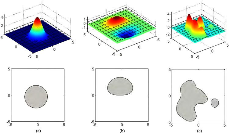
458                                                                               IEEE TRANSACTIONS ON ROBOTICS, VOL. 28, NO. 2, APRIL 2012

to explore the design space in a more stochastic process that         used. Here, we simply impose a global sinusoidal variation in
allows nondirect solutions to be obtained.                            volume of the designated actuation material.
    In previous work, we presented preliminary results of an evo-
lutionary design automation algorithm as applied to simulated         B. Freeform Additive Manufacturing
freeform multimaterial beams and amorphous robots [2], [3]
                                                                         In order to automatically manufacture amorphous soft robots,
and provide a detailed description of the soft-body simulation
                                                                      new technology must be developed with the capability to fab-
engine [4]. Here, were build on these results and demonstrate
                                                                      ricate soft morphologies and actuation. Additive manufactur-
automatic design and manufacturing of static freeform beams
                                                                      ing methods (which is also known as rapid prototyping or 3-D
and dynamic locomoting soft robots (see Fig. 1). The previ-
                                                                      printing) allow for 3-D objects to be fabricated with minimal ge-
ously untested results of the design automation algorithm were
                                                                      ometric constraints. These processes generally slice the target
fabricated and verified in the real world, and the results were
                                                                      geometry into 2-D layers, which are then sequentially fabri-
compared favorably with the predicted performance.
                                                                      cated with finite thickness to build up a 3-D object. Initially,
    The specific scenarios that are explored here are simply rep-
                                                                      these manufacturing techniques were limited to creating objects
resentative of the utility of the evolutionary design automa-
                                                                      of a single homogeneous material, such as steel, resin, or plas-
tion algorithm to meet high-level functional goals. Thus, such
                                                                      tic [12]. However, multimaterial 3-D objects are now possible,
an algorithm can be used not just to design locomoting soft-
                                                                      with the ability to create arbitrary internal material distributions.
robot morphologies but robots to perform other high-level tasks
                                                                      Materials that can be cofabricated include rigid plastics and soft
that could involve sensory input, such as overcoming obstacles,
                                                                      rubbers with as much as three orders of magnitude difference in
fitting through small holes, reacting to environmental changes,
                                                                      stiffness using inkjet technology [15]. Progress has been made
or seeking prey as well. Locomotion is simply a practical in-
                                                                      toward automated fabrication of functional robots with primar-
stance of this design automation method.
                                                                      ily soft materials [13] using extrusion techniques as well [14].
                                                                         Additive manufacturing has been used to facilitate the au-
                                                                      tonomous construction of traditional robots using rigid limbs
A. Soft Robotics                                                      and rotational joints [16]. However, only the structural parts are
                                                                      fabricated automatically and the actuation is then added after-
   Robots traditionally are composed of rigid links that are con-
                                                                      ward by installing motors, batteries, and control circuitry [17].
nected by discrete single DOF rotary or linear actuators. Such
                                                                      Such robots exist within the traditional discrete paradigm of
robots can be very precise and are invaluable and ubiquitous in
                                                                      robots discussed earlier. This severely limits the application of
structured, well-known environments, such as industrial assem-
                                                                      existing methods toward the fabrication of an amorphously ac-
bly lines. Although this precision is desirable in many cases,
                                                                      tuated robot. Attempts to incorporate an electroactive polymer
the downside is a lack of robustness. In order to avoid damage,
                                                                      actuator material directly into the fabrication process have been
the kinematics of these machines must be modeled determinis-
                                                                      demonstrated [13], but the actuator performance is not yet on
tically and then carefully applied to do path planning and avoid
                                                                      par with comparable discrete actuation methods.
collisions.
   However, in uncertain and potentially harsh environments, the
complexity, precision, and fragility of traditional robots can be a   C. Topology Optimization
hindrance. Although robots have long been inspired by various            General shape-optimization techniques seek to optimize the
aspects of biological systems, a new paradigm in robotics has         parameters or shape of an existing structure. In contrast, topol-
recently emerged to replicate their robustness and resilience.        ogy optimization is not bound to a pre-existing structure, shape,
These “soft” robots trade deterministic control for probabilistic     or topology. This allows it more flexibility to adapt to fun-
models, but gain robustness [5]. Many varieties of soft actuators     damentally different solutions. Topological optimization has
have been demonstrated, but several specific actuation methods        been well explored for maximizing rigidity of 3-D elastic struc-
have been explored that show promise for soft robots. These           tures, such as cantilever beams under a predefined loading sce-
include jamming [6], electroactive polymers [7], pneumatics [8],      nario [18], [19]. However, these utilize a single homogeneous
and shape memory alloy (SMA) [9], but all place constraints on        material and optimize only a single parameter, such as stiffness
how the internal locomotion forces can be applied, as well as         per weight of the global structure, in contrast with the mul-
the resulting geometry. A summary of the current research in          timaterial scenario with higher level functional goals that are
deformable soft robots is given in Table I.                           demonstrated here.
   Here, we propose incorporating an isometric volume-                   A homogenization technique to solve this class of topology
changing material for truly distributed actuation without geo-        optimization problems has been demonstrated in [1]. This it-
metric constraints. This allows complete freedom to the design        erative process alternately performs a physical simulation and
automation algorithm over the method and magnitude of lo-             then varies local stiffness based on the results of the previous
comotion is based purely on material distributions. Thus, the         simulation. Pixels that are located in the regions of high strain
function of an evolved soft robot is inextricably paired with its     energy are strengthened, whereas pixels in the regions of low
morphology without imposing additional forces at arbitrary lo-        strain energy are gradually eliminated. The structure as a whole
cations. Since the complexity of how locomotion is achieved is        is updated subject to global constraints on the total volume and
embedded in the shape, a very simple control scheme can be            minimizing the total strain energy under load. Variations on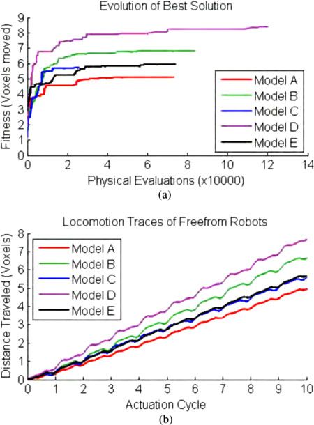
HILLER AND LIPSON: AUTOMATIC DESIGN AND MANUFACTURE OF SOFT ROBOTS                                                                     459

                                                             TABLE I
                                       SUMMARY OF CURRENTLY PUBLISHED DEFORMABLE SOFT ROBOTS

this method have yielded results that maximize deflection or            The level-set concept is versatile and useful for evolving
compliance of an overall object [21] or microstructure [22], or      freeform shapes because there is no prescribed topology of the
even utilize two materials to emulate an actuated structure [20].    object. In the level set method, an n-dimensional height map is
However, homogenization techniques depend on updating each           thresholded into an n-dimensional set of regions. For instance,
location directly based on a global parameter, which generally       a 2-D height map (which can be visualized as a 3-D surface or
limits them to optimizing overall deflection or force. Upon incor-   terrain map) can be thresholded (or chopped) at a specific height
poration of competing objectives or high-level functional goals      to generate the 2-D “topo” regions (see Fig. 2). If the height map
into the optimization as presented in this paper, homogenization     is smooth, then smooth 2-D regions are generated. In order to
approaches become unwieldy or even completely impractical.           generate smooth 3-D regions, a 3-D density field is generated,
   Evolutionary algorithms are often presented as an alterna-        which is then thresholded to create a 3-D solid [28], [29].
tive to homogenization techniques. Evolutionary algorithms are          It is possible to create interesting, smooth 3-D landscapes for
much more general and can accommodate competing objectives           the level-set method with a very reasonable number of evolved
and high level goals, but at the expense of much more process-       parameters. We specifically explore the Gaussian mixtures rep-
ing time. The success of evolutionary algorithms in topology         resentation [30]. In this method, a list of Gaussian points within
optimization depends strongly on the encoding that is used to        the 3-D workspace is maintained. Each point has an associ-
represent the physical object. A direct encoding of the genome       ated density and the Gaussian falloff range. To generate the
is often used in which every individual pixel is stored and ma-      3-D density field, the relative density at each location in the
nipulated by the search algorithm [23], [24]. This method scales     workspace is calculated based on the linear sum of contributions
very poorly to large structures because the number of pixels         from all Gaussian points. An illustration of the Gaussian mix-
scales with the square of the resolution, which directly cor-        tures in two dimensions is shown in Fig. 2. A single point [see
responds to a rapidly increasing size of the genome. In 3-D,         Fig. 2(a)] results in a circular section. Two points [see Fig. 2(b)],
this problem is exaggerated still further because the number         i.e., one positive and one negative, creates a non-uniform shape.
of voxels (3-D pixels) scales with the cube of the resolution.       Twenty randomly generated points [see Fig. 2(c)] generate in-
Thus, efficient representations are key to enabling evolutionary     teresting smooth 2-D shapes. For the results that are presented
algorithms to overcome the functional complexity limitations of      here, this same concept was used in 3-D. Here, we used only
homogenization, especially in three dimensions, as described in      uniform 3-D falloff for the Gaussian points, although represent-
the following section.                                               ing each distribution using a covariance matrix would lead to
                                                                     more complex shapes with more free parameters. This choice of
                                                                     representation implies that solutions will be limited to smooth,
                                                                     freeform shapes rather than the more traditional 3-D primitives
D. Representation for Amorphous Shapes                               that are used in the evolution of robot morphologies. A compar-
                                                                     ison of the performance of the Gaussian mixtures representation
   It is desirable for the representation that is used within an     with other freeform 3-D representations may be found in [3].
evolutionary algorithm to define a desired subspace of sensible         In order to extend the Gaussian mixtures representation to
objects using a minimum number of parameters [25]. Various           multiple materials, a material index for each Gaussian point
graph structures, generative encodings, and constrained bit-wise     is maintained. For each possible material in the simulation, the
encodings that have been proposed to address these challenges        corresponding Gaussian points are rendered to a separate density
have been summarized in [26]. Most examples of evolutionary          field. Then, the final heterogeneous object is determined by
algorithms within the specific field of evolutionary robotics use    the relative density of each material at each location. The total
a collection of 3-D primitives [27] to represent a physical robot.   density of all materials is thresholded to obtain the shape. Within
However, these are not directly conducive to creating smooth         the shape, the material with the highest density at each location
freeform shapes.                                                     is then instantiated.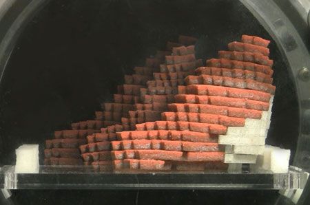
460                                                                                           IEEE TRANSACTIONS ON ROBOTICS, VOL. 28, NO. 2, APRIL 2012

Fig. 2. Level set method of the Gaussian mixtures is illustrated in two dimensions. A single Gaussian density point thresholded at an arbitrary level yields a
circular region. Adding a second point, here with negative density, results in a nonuniform shape. Twenty points yields complex, smooth freeform shapes. This
concept easily extends to three dimensions. (a) One Gaussian point. (b) Two Gaussian points. (c) Twenty Gaussian points.

                       II. ALGORITHM DETAILS                                    voxels for the purpose of simulation. Voxels were chosen over
   Evolutionary algorithms are widely used across many dis-                     a freeform mesh because they more naturally handle simulat-
ciplines for many different optimization problems. A good                       ing multiple interspersed materials. As long as a sufficiently
introduction to this class of algorithms may be found in [31]. Us-              high resolution is chosen to capture the function of the object,
ing the Gaussian mixtures representation, the genome is simply                  this discretization does not adversely affect the evaluation or
a list of points with six parameters each: the X, Y, and Z coor-                construction of continuous shapes.
dinates, density, falloff distance, and material index. Once the
representation has been defined, there are still several choices to             A. Static Analysis
be determined regarding how the design automation algorithm                        The cantilever beam designs were evaluated using the lin-
can generate new designs from preexisting designs. The algo-                    ear direct stiffness method. Materials are assumed to be well
rithm must have defined methods for crossover (combining two                    approximated by a linear isotropic material model and the ge-
preexisting designs into a new design) and mutation (making                     ometry of the beam is assumed to not change significantly. To
small changes to an existing design).                                           evaluate the fitness of a beam, the layer of voxels on the −Y
   For the Gaussian mixtures representation, a one-plane section                plane (base of the cantilever beam) were fixed to ground, while
crossover method was used. For each crossover event, a single                   the layer of voxels at the other end of the beam had a downward
plane is randomly generated that intersects the workspace. The                  force applied to them.
new design consists of all the Gaussian points from one side of                    Each voxel has an associated stiffness and Poisson’s ratio.
the plane from the first parent, as well as all the Gaussian points             Each voxel was modeled with all six translational and rotational
from the other side of the plane from the second parent. This                   DOFs. By calculating the effective translational and rotational
method has the ability to preserve physical regions with helpful                stiffnesses of each link between voxels, a 6n × 6n stiffness
functionality. Mutating the Gaussian mixtures representation                    matrix [K] can be assembled, where n is the total number of
involves making small changes to any of the parameters of a few                 voxels in the simulation. This stiffness matrix relates the relative
Gaussian points and occasionally adding or removing points. A                   displacements Dn and angles θn of each voxel to the applied
mutation rate of 20% was used.                                                  forces Fn and moments Mn . This forms a matrix equation
   An evolutionary algorithm must also have some means of

evaluating the goodness, or fitness, of each new design that it                                         Fn              Dn
produces. This is very specific to the domain of the problem be-                                              = [K ]          .                  (1)
                                                                                                        Mn               θn
ing solved. Since the algorithm that is presented here optimizes
shapes for their properties in the physical world, a physical sim-              To obtain the resulting displacements and angles, this system
ulation must naturally be involved to guide the search process.                 of equations must be solved. Fortunately, the stiffness matrix
For both the static cantilever beams and the soft robots, custom                is extremely sparse, which allows for structures with tens of
simulation software was developed to efficiently do both static                 thousands of DOFs to be solved in less than a second on an
and dynamic analysis. In both cases, the continuous domain                      ordinary desktop computer. This sparse stiffness matrix problem
that is generated by the Gaussian mixtures was discretized into                 was solved using the highly optimized PARDISO solver [32] to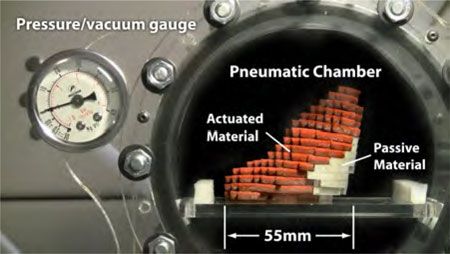
HILLER AND LIPSON: AUTOMATIC DESIGN AND MANUFACTURE OF SOFT ROBOTS                                                                   461

yield the resulting displacements of each voxel of the structure                                 TABLE II
                                                                               SUMMARY OF EVOLUTIONARY ALGORITHM PARAMETERS
under load.

B. Dynamic Analysis
   The soft robots were evaluated using a more general dynam-
ics simulator that is capable of modeling momentum effects and
large deformations of soft materials [4]. Again, each voxel has a
specific stiffness and Poisson’s ratio associated with it. In addi-                  III. STATIC STRUCTURE RESULTS
tion, the density and coefficients of static and dynamic friction
                                                                         Before applying these design automation techniques to soft
also were included for each material. The system was simu-
                                                                      robots, their capability to design heterogeneous multimaterial
lated using an iterative method. Forces between all voxels were
                                                                      structures was verified by designing cantilever beams to deflect
calculated, then positions were updated synchronously using
                                                                      in to prescribed shapes under downward load. A slender can-
numerical integration. This allows for the inclusion of nonlinear
                                                                      tilever beam with a homogeneous material distribution deflects
effects, such as a soft shape bending over double or Coulomb
                                                                      in a polynomial cubic curve. By incorporating a finite thickness
stick–slip friction that are not possible to accommodate using
                                                                      for the beam and a combination of hard and soft materials, it
the direct stiffness method. The friction between the soft robot
                                                                      is possible to change this deflected profile into other smooth
and the floor was implemented in a manner that is consistent
                                                                      downward sloping profiles based on the material distribution
with the basic Coulomb friction model: any voxel touching the
                                                                      (see Fig. 3).
floor was either stopped or in a state of motion that is relative
                                                                         In order to facilitate the emergence of the correct qualitative
to the floor. Stopped voxels resisted any lateral motion until the
                                                                      shapes, differences in quantitative deflection of competing de-
lateral force exceeded the product of the normal force and the
                                                                      signs were not penalized. In order for the design algorithm to
coefficient of static friction. Voxels in motion were slowed by a
                                                                      evaluate each design, the beam was loaded and simulated to es-
frictional force according to the coefficient of dynamic friction
                                                                      timate the deflected shape. Both desired and simulated profiles
multiplied by the current normal force.
                                                                      were normalized so that the free end had unit deflection. Then,
   Individual interactions between voxels were modeled as
                                                                      points along top surface of each deflected beam were recorded
beams according to the Euler–Bernoulli beam theory, with phys-
                                                                      and compared with the desired profile. The workspace of the
ical parameters set to the appropriate values based on the size
                                                                      beam was selected to be 12 × 12 × 40 (5760 total) voxels.
of the voxels and the distance between them. Again, 6 DOF per
                                                                      With a domain this much large, the simulation is the computa-
voxel were used to enable both translational and rotational free-
                                                                      tional bottleneck of the design automation algorithm. Because
dom. Volumetric actuation was achieved in simulation by simply
                                                                      the Gaussian mixtures representation can be discretized at any
changing the rest length between adjacent actuating voxels in
                                                                      arbitrary resolution, the design process was accelerated by first
all three dimensions. It was assumed that the volume chang-
                                                                      evaluating designs at low resolution (6 × 6 × 20 voxels). After
ing actuation effects were fast compared with the response of
                                                                      the algorithm began to converge on good solutions, the algorithm
the structure itself. Thus, the propagation and equalization of
                                                                      automatically switched to the higher resolution evaluation. A
air pressure was not modeled. In addition, a collision detec-
                                                                      single fitness metric was calculated for each beam regardless of
tion system was in place to ensure that the soft robots did not
                                                                      resolution as the sum of the squared differences between each
self-penetrate.
                                                                      voxel on the top surface and the desired top-surface profile.
                                                                         A total of four different beam profile shapes were tested
                                                                      in addition to verifying the deflected shape of the homoge-
C. Evolutionary Algorithm Parameters
                                                                      neous beams. In approximate increasing order of difficulty,
   The method of selecting which designs to combine and the           these include a straight profile, a circular-arc-shaped profile, a
criteria for when to keep a new design has a significant effect       discontinuous-slope profile, and a fourth-order-polynomial pro-
on the success of a evolutionary algorithm. Here, we use the de-      file that incorporated negative (upward) curvature. After running
terministic crowding selection method [33]. In this method, two       for several thousand generations, the design automation algo-
random individuals from the current population are selected for       rithm was able to match the simulated shape with a high degree
breeding. After the crossover process is completed to generate        of accuracy to each desired profile.
a candidate offspring design, the amount of evolutionary contri-         In order to verify the performance of the design automation
bution from each parent is evaluated to determine the dominate        in the physical world, each beam was autonomously fabricated
parent. After a 20% chance of mutation for each parameter,            in 3-D using an Objet Connex 500 printer. First, a homogeneous
the candidate solution is evaluated using the physics simula-         beam was printed and tested to verify the experimental proce-
tor. If the child design is more fit than its dominate parent, the    dure (see Fig. 4) with favorable results. Because the shapes were
child replaces this parent in the current population. Otherwise,      only being compared qualitatively, the absolute stiffness of the
the new design is discarded. This method allows for relatively        physical materials did not have to be exact. However, the ratio
small population sizes, while maintaining diversity. In Table II,     of stiffnesses of the two materials was important to replicate
we summarize the details of the evolutionary algorithm.               the designed shapes in the physical world. A combination of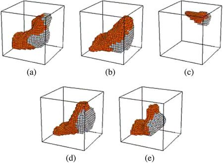
462                                                                                                 IEEE TRANSACTIONS ON ROBOTICS, VOL. 28, NO. 2, APRIL 2012

Fig. 3. Autonomously designed material distributions of static cantilever beams deflect in nontraditional top-surface profiles, such as a straight line (first column),
circular arc (second column), discontinuous slope (third column), and fourth-order polynomial (fourth column). The generated material distributions (a)–(d) and
the corresponding simulated deflected profiles (e)–(h) closely match the input functions. Actual beams were autonomously fabricated and tested (i)–(l). The results
for both simulation and reality are compared with the desired shape and nominal shape (m)–(p).

                                                                                     Objet’s VeroGrey (hard) and TangoPlus (soft) were used. Be-
                                                                                     fore printing, additional geometry was appended to each shape
                                                                                     to facilitate physical testing. This included a base block to be
                                                                                     clamped to ground and loops to enable force to be evenly applied
                                                                                     at the free end.
                                                                                        Each design was printed out and tested. In order to compare
                                                                                     the actual resulting physical beams with the expected results,
                                                                                     we used image analysis to analyze the deflected profile of each
                                                                                     beam. The test beam was firmly clamped at the fixed end, while
                                                                                     enough downward force was manually applied to the free end to
                                                                                     achieve a nontrivial deflection. An image of the beam was then
                                                                                     captured from the side with the lighting and background setup
                                                                                     to facilitate the accurate edge detection.
                                                                                        The process of extracting the profile of the beam from each
                                                                                     image is shown in Fig. 5. First, an edge-finding filter was ap-
                                                                                     plied in Photoshop. The result was then thresholded into a black
                                                                                     and white image. Extraneous image noise not connected to the
                                                                                     profile of the beam was eliminated. A MATLAB script then
                                                                                     determined the average height of the black pixels for each col-
                                                                                     umn of the image to create a 1-D function. This function was
Fig. 4. Test beam of homogeneous material distribution was fabricated to
verify the experimental setup. The rms error in deviation from the expected
                                                                                     then smoothed using the locally weighted scatterplot smoothing
profile is about 1.25%.                                                              (LOWESS) method with a linear fit over a span of 101 pixels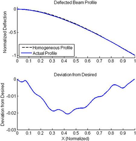
HILLER AND LIPSON: AUTOMATIC DESIGN AND MANUFACTURE OF SOFT ROBOTS                                                                                              463

Fig. 5. To extract the profile of a deflected beam, an image of each beam
was captured in its deflected state. Edge-finding filter was applied followed
by a thresholding filter to create a black and white image. Pixels that are not
associated with the top surface of the beam were then manually erased to allow
the profile to be detected and segmented with a MATLAB script. (a) Original
image. (b) Edge find. (c) Threshold. (d) Segment.

                             TABLE III
       RMS ERROR IN DEVIATION OF SIMULATED AND ACTUAL BEAMS

                                                                                  Fig. 6. Best results of five independent evolutionary algorithm runs designing
                                                                                  freeform soft robots. (a) Fitness increases dramatically at first, then in smaller
in the X-direction. This sufficiently smoothes out the effects of                 jumps corresponding to new discoveries, but eventually leveling off. (b) Move-
image noise, while retaining the actual shape of the beam. The                    ment of the best soft robot at the end of each run shows very similar locomotion
resulting function is then normalized and compared with the                       pattern.
simulated and desired function and the rms error between each
is calculated. The results are given in Table III.
                                                                                  mentation that is used to demonstrate the freeform robot in the
                                                                                  real world. We chose the representative values of 0.3 and 1 for
            IV. DYNAMIC FREEFORM ROBOT RESULTS                                    dynamic and static friction, respectively.
   The same design automation algorithm was then applied to                          A resolution of 20 × 20× 20 (8000 possible) voxels was
create locomoting freeform soft robots by simply changing the                     selected as a reasonable-sized domain to work within. The low-
criteria for how a candidate design was calculated. Using the                     resolution bootstrapping of initial solutions was not utilized for
dynamic simulator described earlier, 10 actuation cycles were                     the dynamic simulation because of abundant available com-
imposed on each design. The fitness was taken to be the dis-                      puting power. Each random solution was initialized with 88
tance, in the positive X-direction, the center of mass moved.                     randomly generated Gaussian points, which was sufficient to
Because the 3-D shapes are initialized in free space, each shape                  create a range of interesting topologically varied shapes. Al-
was allowed to settle under gravity before the actuation com-                     though mutation operators occasionally add or subtract points
menced. The center of mass was then calculated and stored for                     from this total, the final solutions generally had around 100 total
comparison with the ending center of mass. This eliminated the                    points. The evolution history of five separate runs of the evolu-
propensity of the algorithm to “cheat” by creating designs that                   tionary algorithm is shown in Fig. 6(a). The solutions were run
simply fell and flopped over in the right direction, but did not                  for an arbitrary amount of time on a single desktop computer,
actually locomote.                                                                ranging from overnight to a couple of days, corresponding to
   In these experiments, the volumetrically actuated material                     tens of thousands of individual physics simulations.
varies sinusoidally in volume over time. The volume change                           All five solutions are shown in Fig. 7. The fundamental mode
was selected to be ±20%. The relative speed (period) of this                      of locomotion is similar for all of them, as evidenced by very
oscillation determines to what degree the dynamics of the struc-                  similar traces of position of the center of mass over time [see
ture play a role in the movement. Fast oscillations around the                    Fig. 6(b)]. All examples exhibit a scooting motion, where the
effective resonance of the shape will result in physical motion                   expanding phase of the actuator pushes the soft robot forward,
substantially out of phase with the input. Here, we selected the                  while the contraction phase resets the back of the robot to re-
oscillation period to be significantly slower that any resonances                 peat. The distribution of the mass of the robot alternately weights
so that the dynamic response of the structure does not dominate                   and unweights the front and back of the robot as the material
the motion. This is to more closely match the physical imple-                     actuates, allowing it to make and break static friction at the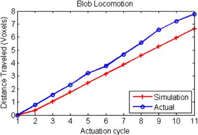
464                                                                                          IEEE TRANSACTIONS ON ROBOTICS, VOL. 28, NO. 2, APRIL 2012

                                                                                                             TABLE IV
                                                                                          COMPARISON OF SIMULATED AND PHYSICAL SOFT ROBOTS

                                                                                assembled onto alignment pins with glue interspersed between
                                                                                layers to finish the 3-D structure. Although this process is not
                                                                                yet fully autonomous, human involvement is minimal, and no
                                                                                particular skill is needed to stack and assemble the fabricated
                                                                                layers.
Fig. 7. Resulting freeform robots of the five evolution runs all converged to
similar morphologies and locomotion modes for the physical parameters that         The robot was chosen to be 55 mm in length in order to
are assigned in these experiments.                                              use commonly available foam rubber sheet stock. Based on the
                                                                                the simulated size, density, and actuation period of the evolved
                                                                                solutions, this size gave a similar scale of relative dynamic
appropriate places and times to achieve locomotion. The simi-                   internal forces when actuated with a period of approximately
larity of the solutions demonstrates that for the given algorithm               10 s. The effective dynamic actuation force Fd for each case
and physical parameters that are used, there is a clear evolu-                  was calculated according to
tionary path from the more complex and topologically varied                                                 Fd = m|a|                             (2)
random initializations to the much simpler class of optimized
designs that resulted. Although these cannot be guaranteed to                   where m is the mass of the total robot, and |a| is the magni-
be a global optimum, the convergent morphologies demonstrate                    tude of the acceleration assuming sinusoidal actuation. Given
that these solutions are at least a very broad local optimum for                an actuator displacement d that is proportional to the size of the
the physical parameters that are used in these tests.                           robot and an actuation frequency f , an effective position P can
   Different physical parameters would likely yield other mor-                  be modeled as
phologies and modes of locomotion. The parameters that are                                               P (t) = dsin(f t)                        (3)
used here are analogous to a very soft gelatinous substance. This
favors the scooting motion observed because there is a high ratio               which when differentiated twice yields
of floor-contact surface area to volume, tending to discourage                                          A(t) = df 2 sin(f t)                      (4)
legged creatures, which would have a much lower ratio. Uti-
lizing stiffer lighter materials would introduce the possibility                where A is the effective acceleration. Thus, the magnitude of
of legged locomotion, but further work is needed to explore the                 acceleration |A| is
different classes of solutions that lie within this broad parameter                                          |A| = df 2                           (5)
space.
   Of the five designs, model B was selected for fabrication.                   so that
A significant missing link in demonstrating true freeform soft
                                                                                                            Fd = mdf 2 .                          (6)
robots is the current inability to 3-D print volumetric actuators.
In order to physically demonstrate the design that is presented                 This effective dynamic actuation force is not quantitatively
here, we rely on modulating the external environment in order                   meaningful, but for a given geometry of soft robot, it provides
to achieve selective volumetric expansion and contraction of au-                a qualitative measure of the similarity of behavior under sinu-
tonomously fabricated regions. By varying the pneumatic pres-                   soidal actuation. For the parameters used here, the simulation
sure of the environment, regions of the soft robot that are pneu-               soft robot had an Fd value of 6.15 μN , and the actual robot had a
matically isolated from the environment experience a change in                  value of 6.09 μN (see Table IV). An acrylic floor was chosen for
relative pressure. Because the surrounding material is soft, this               the physical experiments. When coupled with the silicone foam
results in a change of volume. Regions of the robot that are pneu-              rubber of the soft robot, the interface exhibited the expected
matically connected to the environment can quickly equalize to                  stick–slip frictional characteristic utilized in the simulation. The
the changing external pressure; therefore, no volume change is                  exact tuning of frictional coefficients was determined to not
observed.                                                                       be critical to the performance of the robot since the locomo-
   Here, we used a custom-layered manufacturing process using                   tion pattern depended primarily on making and breaking static
preexisting open-cell and closed-cell foam rubbers to fabricate                 friction.
the robots. A routine was written to send the profile of each voxel                The physical robot was placed in a pressure and vacuum
layer to a laser cutter to be autonomously cut out, along with                  chamber to verify the locomotion (see Fig. 8). The trace of the
alignment holes between layers. The individual layers were then                 position of the physical robot at the end of each actuation cycle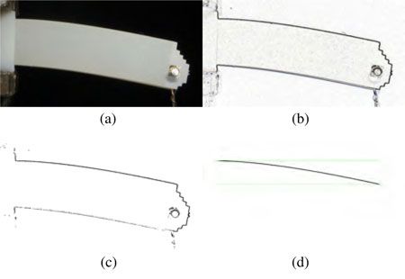
HILLER AND LIPSON: AUTOMATIC DESIGN AND MANUFACTURE OF SOFT ROBOTS 465
V. CONCLUSION
For decades of mechanisms and robotics, the paradigm of dis-
crete rigid links and single-DOF joints has prevailed. Here, the
effectiveness of evolutionary algorithms paired with the Gaus-
sian mixtures representation to autonomously design freeform
shapes and material distributions to achieve high-level function-
ality in the physical world has been demonstrated. The same
algorithm can be applied to very different mechanical design
problems by simply changing the function that evaluates: How
good a potential design is? This is easily extended to exploring
multiple, competing objectives by incorporating a Pareto front
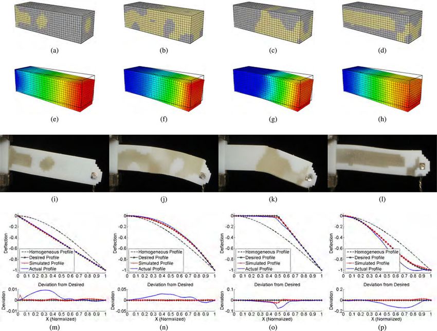
Fig. 8. Soft robot was placed in a pneumatic pressure/vacuum chamber to of solutions.
demonstrate locomotion. Selective volumetric actuation was attained using
closed cell (orange) foam rubber, which changes volume as the air pressure In the future, we envision directly manufacturing pneumat-
changes periodically. Open cell foam rubber (white) does not change volume. ically actuated soft robots with additive manufacturing tech-
niques. By utilizing soft, elastic material, discrete hollow cells
could be fabricated. Those which are sealed off from the exterior
environment would act as actuators and others which are open
to the environment would be passive. By the incorporation of
a source of pressure connected to the sealed actuation regions,
the designs that are presented here would work without adapta-
tion in our everyday environment, where atmospheric pressure
is constant. This would also allow more complex actuation pat-
terns, such as out-of-phase actuation of different regions of the
soft robot. With such distributed actuation, morphological com-
putation could also be explored for the purpose of controlling
gaits.
With the unconstrained design space enabled by multimaterial
additive manufacturing techniques, a whole new design space
Fig. 9. Movement of the simulated and actual model B soft robot shows of soft, amorphous robots is possible. There are still challenges
similar velocities, suggesting that the physics simulator is an accurate predictor that remain regarding how to effectively design functional ob-
of real-world performance.
jects with discrete components and how to best actuate a truly
amorphous soft robot. We believe that volumetric actuation pro-
vides a viable method for actuating soft robots and offers many
advantages for design automation because locomotion is dic-
is plotted with the simulation results (see Fig. 9). In each case, tated purely by material distributions. However, more work is
the distance traveled is normalized by the size of the voxels. The needed to develop self-contained and powered volumetrically
physical robot displays robust locomotion and progresses at a actuating materials. As these challenges are addressed, robots
very similar rate as the simulation predicts. will be better equipped to operate robustly in highly uncertain
The ability of the physical robot to match the simulation ve- and dangerous environments.
locity can be attributed to several key parameters. The most
important by far is the percent volumetric actuation. If the ac-
tuation is not large enough to ever break the static friction with REFERENCES
the floor, the robot will never move. Once the actuation amount [1] M. P. Bendsoe and N. Kikuchi, “Generating optimal topologies in struc-
has reach this threshold, the velocity of the robot per actuation tural design using a homogenization method,” Comput. Methods Appl.
cycle will increase as the amount of actuation increases. By Mech. Eng., vol. 71, no. 2, pp. 197–224, 1988.
[2] J. Hiller and H. Lipson, “Multi-material topological optimization of struc-
extension, as long as the available actuation force is large com- tures and mechanism,” in Proc. Genetic Evol. Comput. Conf., 2009,
pared with the frictional forces and the friction coefficients are pp. 1521–1528.
such that static friction is in effect at the appropriate periods of [3] J. Hiller and H. Lipson, “Evolving amorphous robots,” in Proc. 12th Int.
Conf. Artif. Life, 2010, pp. 717–724.
each cycle, the exact friction coefficient values are not critical. [4] J. Hiller and H. Lipson, “Dynamic simulation of soft heterogeneous ob-
The combined passive and actuator material properties dictate jects,” 2012, to be published.
the change in pressure that is necessary to achieve a given actu- [5] J. Rieffel, B. Trimmer, and H. Lipson, “Mechanism as mind: What tenseg-
rities and caterpillars can teach us about soft robotics,” in Proc. 11th Int.
ation amount, but once this is calibrated to the simulation, the Conf. Artif. Life, 2008, pp. 506–512.
stiffness of these materials plays a secondary role in semistatic [6] A. Mozeika, E. Steltz, and H. M. Jaeger, “The first steps of a robot based
locomotion that was specified by the optimization algorithm. A on jamming skin enabled locomotion,” in Proc. IEEE/RSJ Int. Conf. Intell.
Robot. Syst., Oct. 11–15, 2009, pp. 408–409.
composite image of three frames of a video shows the phys- [7] Y. Bar-Cohen, Electroactive Polymer (EAP) Actuators as Artificial
ical robot locomoting under the varying relative pressure (see Muscles—Reality, Potential and Challenges, vol. PM98. Bellingham WA:
Fig. 1). SPIE, 2001.466 IEEE TRANSACTIONS ON ROBOTICS, VOL. 28, NO. 2, APRIL 2012
[8] J. Rieffel, F. Saunders, S. Nadimpalli, H. Zhou, S. Hassoun, J. Rife, and [30] F. Pernkopf and D. Bouchaffra, “Genetic-based EM algorithm for learning
B. Trimmer, “Evolving soft robotic locomotion in physx,” in Proc. Genetic Gaussian mixture models,” IEEE Trans. Pattern Anal. Mach. Intell.,
Evolutionary Comput. Conf., New York: ACM, 2009. vol. 27, no. 8, pp. 1344–1348, Aug. 2005.
[9] Y. Sugiyama and S. Hirai, “Crawling and jumping by a deformable robot,” [31] D. Goldberg, Genetic Algorithms in Search, Optimization and Machine
Int. J. Robot. Res., vol. 25, no. 5–6, pp. 603–620, 2006. Learning. New York: Addison-Wesley, 1989.
[10] B. A. Trimmer, A. E. Takesian, B. M. Sweet, C. B. Rogers, D. C. Hake, [32] O. Schenk and K. Gartner, “Solving unsymmetric sparse systems of linear
and D. J. Rogers, “Caterpillar locomotion: A new model for softbodied equations with pardiso,” Future Gener. Comput. Syst., vol. 20, no. 3,
climbing and burrowing robots,” in Proc. 7th Int. Symp. Technol. Mine pp. 475–487, 2004.
Problem, Monterey, CA, 2006. [33] S. Mahfoud, “Niching methods for genetic algorithms,” Ph.D. dissertation,
[11] F. Ilievski, A. D. Mazzeo, R. F. Shepherd, X. Chen, and G. M. Whitesides, Dept. Comput. Sci., Univ. Illinois, Urbana, IL, 1995.
“Soft robotics for chemists,” Angewandte Chemie Int Ed., vol. 50, pp.
1890–1895, 2011.
[12] J. J. Beaman, H. L. Marcus, D. L. Bourell, J. W. Barlow, R. H.
Crawford, and K. P. McAlea, Solid Freeform Fabrication: A New Di-
rection in Manufacturing, Norwell, MA: Kluwer, 1997.
[13] E. Malone, K. Rasa, D. Cohen, T. Isaacson, H. Lashley, and H. Lipson,
“Freeform fabrication of zinc-air batteries and electromechanical assem-
blies,” Rapid Prototyp. J., vol. 10, no. 1, pp. 58–69, 2004.
[14] E. Malone and H. Lipson, “Fab@home: The personal desktop fabricator Jonathan Hiller received the B.S. degree in
kit,” Rapid Prototyp. J., vol. 13, no. 4, pp. 245–255, 2007. mechanical engineering from the University of
[15] Objet. (2010). Objet geometries Inc. [Online]. Available: http://www. Washington, Seattle, in 2006 and the M.S. and Ph.D.
objet.com degrees in mechanical engineering in 2009 and 2011,
[16] H. Lipson and J. B. Pollack, “Automatic design and manufacture of robotic respectively, from Cornell University, Ithaca, NY.
lifeforms,” Nature, vol. 406, no. 6799, pp. 974–978, 2000. He was a Member of the Cornell University Com-
[17] J. B. Pollack, H. Lipson, G. Hornby, and P. Funes, “Three generations of putational Synthesis Laboratory. He was a member
automatically designed robots,” Artif. Life, vol. 7, no. 3, pp. 215–223, of the Sibley School of Mechanical and Aerospace
2001. Engineering, Cornell University. His research inter-
[18] A. Diaz and R. Lipton, “Optimal material layout for 3D elastic structures,” ests include the boundary between the physical and
Struct. Multidiscipl. Optim., vol. 13, no. 1, pp. 60–64, 1997. digital world, specifically, the automated design and
[19] P. Fernandes, J. M. Guedes, and H. Rodrigues, “Topology optimization of fabrication of voxel-based materials and functional systems.
three-dimensional linear elastic structures with a constraint on perimeter,” Dr. Hiller received the National Science Foundation Graduate Research
Comput. Struct., vol. 73, no. 6, pp. 583–594, 1999. fellowship.
[20] M. J. Buehler, B. Bettig, and G. G. Parker, “Topology optimization of
smart structures using a homogenization approach,” J. Intell. Mater. Syst.
Struct., vol. 15, no. 8, pp. 655–667, 2004.
[21] S. Nishiwaki, M. I. Frecker, S. Min, and N. Kikuchi, “Topology optimiza-
tion of compliant mechanisms using the homogenization method,” Int. J.
Numer. Methods Eng., vol. 42, no. 3, pp. 535–559, 1998.
[22] O. Sigmund and S. Torquato, “Design of smart composite materials using
topology optimization,” Smart Mater. Struct., vol. 8, pp. 365–379, 1999.
[23] M. J. Jakiela, C. Chapman, J. Duda, A. Adewuya, and K. Saitou, “Contin- Hod Lipson (M’02) received the B.Sc. degree in me-
uum structural topology design with genetic algorithms,” Comput. Meth- chanical engineering and the Ph.D. degree in me-
ods Appl. Mech. Eng., vol. 186, no. 2–4, pp. 339–356, 2000. chanical engineering in computer-aided design and
[24] C. Kane, “Topological optimum design using genetic algorithms,” Control artificial intelligence in design from the Technion—
Cybern., vol. 25, no. 5, pp. 1059–1088, 1996. Israel Institute of Technology, Haifa, Israel, in 1989
[25] C. Kane and M. Schoenauer, “Genetic operators for two-dimensional and 1998, respectively.
shape optimization,” in Proc. Artif. Evol., 1996, pp. 355–369. He is currently an Associate Professor with the
[26] R. Kicinger, T. Arciszewski, and K. D. Jong, “Evolutionary computation Mechanical and Aerospace Engineering and Comput-
and structural design: A survey of the state-of-the-art,” Comput. Struct., ing and Information Science Schools, Cornell Univer-
vol. 83, no. 23–24, pp. 1943–1978, 2005. sity, Ithaca, NY. He was a Postdoctoral Researcher
[27] K. Sims, “Evolving virtual creatures,” in Proc. SIGGRAPH, New York, with the Department of Computer Science, Brandeis
ACM, Jul. 24–29, 1994, pp. 15–22. University, Waltham, MA. He was a Lecturer with the Department of Mechan-
[28] J. A. Sethian and A. Wiegmann, “Structural boundary design via level set ical Engineering, Massachusetts Institute of Technology, Cambridge, where he
and immersed interface methods,” J. Comput. Phys., vol. 163, pp. 489– was engaged in conducting research in design automation. His current research
528, 2000. interests include computational methods to synthesize complex systems out
[29] M. Y. Wang, X. Wang, and D. Guo, “A level set method for structural of elementary building blocks and the application of such methods to design
topology optimization,” Comput. Methods Appl. Mech. Eng., vol. 192, automation and their implication toward understanding the evolution of com-
no. 1–2, pp. 227–246, 2003. plexity in nature and in engineering.You can also read