B.C. Community ROAD SAFETY - TOOLKIT
←
→
Page content transcription
If your browser does not render page correctly, please read the page content below
B.C. Community
ROAD SAFETY
TOOLKIT

                                     Module 2:
Safe Roadway Designs to Protect All Road Users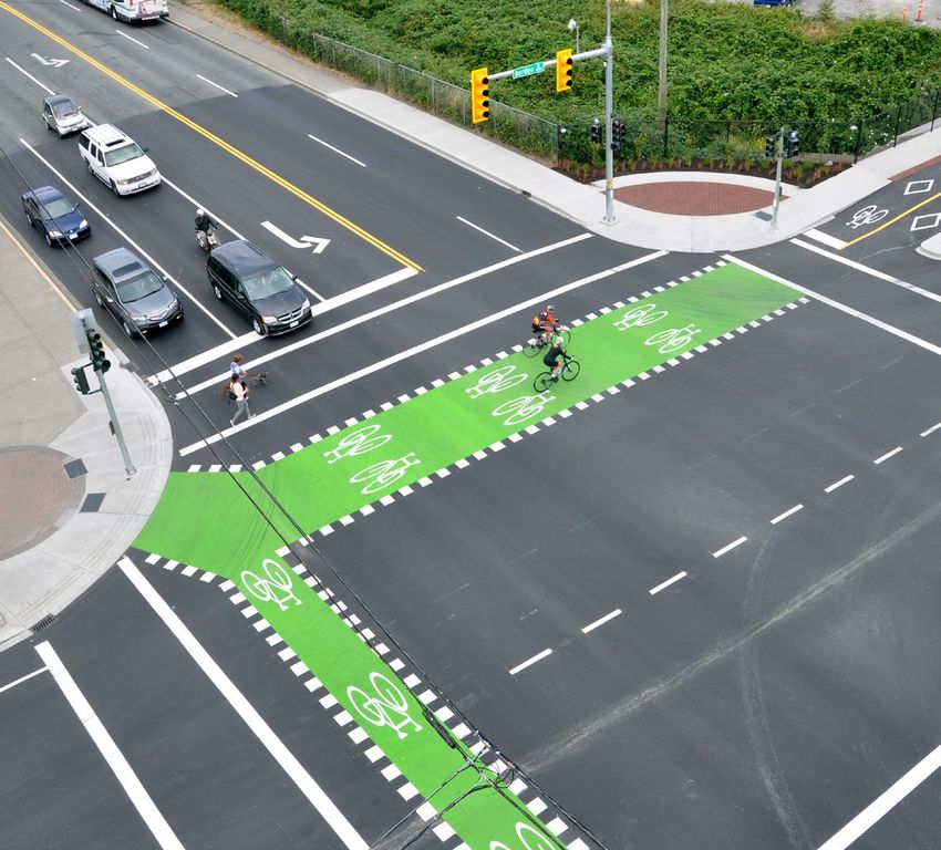
Module 2:
Safe Roadway Designs to Protect All Road Users

Disclaimer: This toolkit is designed to consolidate
and disseminate knowledge about proven and
promising road safety designs, strategies, and devices,
rather than to provide technical knowledge.
A strong effort was made to find and incorporate the
most valid and reliable research about the various
strategies in the toolkit. However, the nature of road
safety research is such that knowledge on road
safety continues to change, and therefore any claims
drawn from the research should be approached
with a critical mind. Local road authorities wishing to
implement any designs, strategies, and devices in this
toolkit should do so under the guidance of trained
and professionally-certified engineers and experts.

                                                          2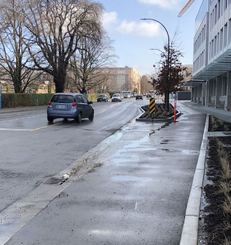
B.C. Community ROAD SAFETY TOOLKIT
   Module 2: Safe Roadway Designs to Protect All Road Users
Table of Contents           Resource Kit
2    Introduction                                         39   Defined Terms
5    Reducing Driver Speeds                               40   Reducing Driver Speeds
6    Lowering of Speed Limits                             40   Lowering of Speed Limits
7    Narrowed Vehicle Lanes                               40   Narrowed Vehicle Lanes
8    Chicanes                                             41   Chicanes
9    Speed Humps                                          41   Speed Humps
10   Speed Reader Boards                                  41   Speed Reader Boards
11   Gateways                                             42   Gateways
12   Traverse Rumble Strips                               42   Transverse Rumble Strips

13   Safe Intersection Design                             43   Safe Intersection Design
14   Prohibiting Right-turn on Red                        43   Prohibiting Right-turn on Red
15   Convert Two-way Stop Control                         43   Convert Two-way Stop Control
     to All-way Stop Control                                   to All-way Stop Control
16   Advance Traffic Signal Warning Lights                44   Advance Traffic Signal Warning Lights
17   Roundabout Design for Cyclists and Pedestrians       44   Roundabout Design for Cyclists and Pedestrians
19   Eliminating and Redesigning Slip Lanes               45   Eliminating and Redesigning Slips Lanes
21   Left-turn Lanes and Signalization                    46   Left-turn Lanes and Signalization
22   Right-turn Lanes at Intersections                    46   Right-turn Lanes at Intersections
23   Reduced Access Point Density                         47   Reduced Access Point Density in
     in the Vicinity of Intersections                          the Vicinity of Intersections
24   Smaller Corner Radii                                 47   Smaller Corner Radii

25   Safe Corridor Design                                 48   Safe Corridor Design
26   Continuous Raised Median Barrier                     48   Continuous Raised Median Barriers
27   Continuous Centre Two-way                            48   Continuous Centre Two-way
     Left-turn Lanes                                           Left-turn Lanes
28   Drainage                                             48   Drainage
29   High Friction Pavement                               49   High-friction Pavement
30   Highly Readable and                                  49   Highly Readable and
     Well-positioned Road Signs                                Well-positioned Road Signs
32   Winter Maintenance of Roads                          50   Winter Maintenance of Roads
33   Improved Lane Markings                               50   Improved Lane Markings
34   Improved Street Lighting                             51   Improved Street Lighting
35   Reduced Access Point Density                         51   Reduced Access Point Density
36   Safe Parking Lots and Parking Lot                    52   Safe Parking Lots and Parking Lot
     Driveways for Pedestrians and Cyclists                    Driveways for Pedestrians and Cyclists

                                                          54   Acknowledgements

                                                      3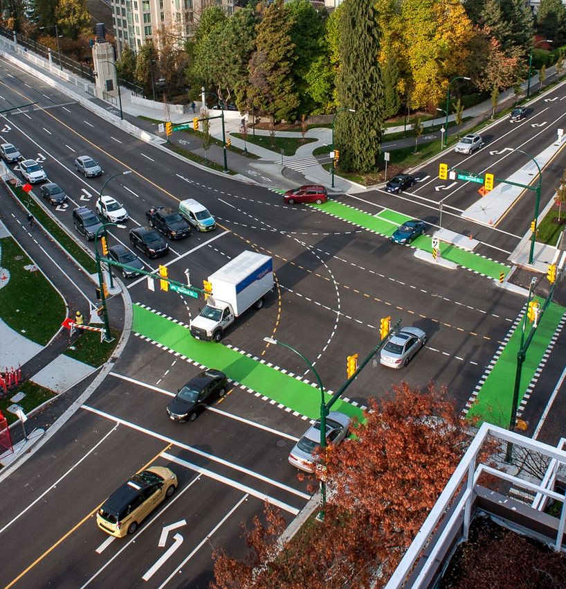
B.C. Community ROAD SAFETY TOOLKIT
  Module 2: Safe Roadway Designs to Protect All Road Users
Safe Roadway Designs to Protect All Road Users
This is the second module of the three-part BC Community Road Safety Toolkit. This module builds on the
first by introducing roadway designs and traffic engineering strategies to improve the safety of all road users,
including pedestrians, cyclists and motor vehicle occupants.
This module has a strong focus on roadway designs and strategies that help reduce driver speeds. Managing driver
speed is critical because it is one of the basic risk factors affecting road safety. At faster speeds, drivers have less
control and less time to react to other road users and hazards. When a crash does occur, the consequences are
more severe due to the greater impact forces.
The module also focuses on intersection safety. According to data gathered by police, 27% of all motor vehicle
crash deaths in British Columbia between 2006 and 2015 occurred at intersections. During this time, the annual
number of road fatalities occurring at non-intersection locations has decreased steadily, while the number
of fatalities at intersections has remained relatively steady. By making stronger efforts to build new safely-
designed intersections and improving existing ones using a number of proven methods, the risk of serious
injuries and fatalities at intersections can be reduced significantly.
Finally, this module introduces some designs and strategies to help improve safety for motor vehicle occupants
and vulnerable road users, including pedestrians and cyclists, in road corridors.

In order to use this module, please see the Resource Kit section, which contains:
¡ Defined terms;
¡ Evidence of effectiveness for each safety design, strategy, or device in Module 2; and
¡ Further resources containing additional information on each item in Module 2.
This module should be read alongside Module 1 – Protecting People Walking and Cycling, which contains
roadway designs that will complement those contained in this document and will help in improving safety for
people walking and cycling.

                                                           4
B.C. Community ROAD SAFETY TOOLKIT
   Module 2: Safe Roadway Designs to Protect All Road Users
Reducing Driver Speeds
Reducing driver speed is one of the most effective ways to improve road safety outcomes.
By reducing speeds, the roadway designs and strategies contained in this section can
help give road users more time to react safely to one another, provide drivers with
greater control and reduce kinetic forces when crashes do occur.

                                       5
B.C. Community ROAD SAFETY TOOLKIT
     Module 2: Safe Roadway Designs to Protect All Road Users
Lowering of Speed Limits
Description
Reducing posted speed limits is one of the simplest and most cost-effective ways of reducing travel
speeds. Speed limits of 50 km/h on most residential streets where there are pedestrians or cyclists are
not consistent with research findings on safe speeds, or with best practices for speed management.
In many cities around the world, communities and road safety authorities have acknowledged
that 50 km/h speed limits in these situations are unsafe. For example, “20’s Plenty for Us” is a non-
profit organization in the United Kingdom that has successfully campaigned for 20 mph (32 km/h)
default speed limits on residential and urban streets. Canadian cities such as Edmonton, Montreal, and
Toronto have recently made systematic efforts to implement 30 km/h speed limits across wide zones.

Reducing Speed Limits                                          with the change in speed limit, otherwise there could
                                                               be a net deterioration in safety if lower speed limits
in BC Municipalities                                           are not reasonable, resulting in higher level of non-
Under the provincial Motor Vehicle Act (MVA), the              compliance.
default speed limit for urban municipalities is 50 km/h,
and 80 km/h for highways outside municipalities.               Typical Implementation
This means that, unless otherwise posted, drivers
must follow the default speed limits.
                                                               Considerations
Under Section 146 of the MVA, municipalities may               In the absence of added enforcement, some drivers
enact a bylaw that sets a different speed limit from the       may not reduce their speeds following speed reductions.
statutory default. The MVA requires that a speed limit         More consistent speed reductions can be achieved
sign be posted on each road with a reduced limit.              through applying physical speed reduction counter-
                                                               measures, such as the ones found in this toolkit,
Evidence of Effectiveness                                      including chicanes, speed humps, and narrowed
                                                               lanes and roads. This measure may also be combined
There is strong evidence that 30 km/h, speed limits in
                                                               with speed reader boards to improve compliance
urban and suburban areas, where cars mix with
                                                               with speed limits.
pedestrians or cyclists, reduces motor vehicle crashes,
fatalities, and injuries, and reduces injury severity
when crashes occur. A study on reduced speed limits
in London, England, found that after adjusting for
other underlying trends over a 20-year period, 20
mph (32 km/h) speed limits resulted in 41.9%
reduction in road casualties.
The positive effect was greatest in younger children.
A study on speed management in European countries
confirmed that speed limit reductions can significantly
reduce speeds and crashes. A study in the United
States also found a significant increase in motor
vehicle crashes and fatalities following interstate
highway speed limit increases in 23 states.
The road form and function should be consistent

                                                           6
B.C. Community ROAD SAFETY TOOLKIT
  Module 2: Safe Roadway Designs to Protect All Road Users
Narrowed Vehicle Lanes
Description
Vehicle lane widths in urban areas are commonly set between 3.3 to 4.0 metres. Reducing urban
vehicle lanes widths to between 2.75 to 3.0 metres, however, has numerous safety and
practical benefits.

How It Works                                                   One study found that where lanes had been
                                                               narrowed from 12 feet (3.66 metres) to 9 to 11 feet
Narrower lanes influence drivers’ perception of
                                                               (2.75 to 3.36 metres), there were fewer fatal and injury
their margin of error, causing them to slow down.
                                                               crashes, or that the number of fatal and injury crashes
Reducing speeds, meanwhile, increases the objective
                                                               remained unchanged.
margin of error, while also making crashes less severe
when they do occur.                                            A study commissioned by the City of Surrey found
                                                               that the reduction of travel lane widths on some
Reducing lane width can also help create space for
                                                               of the city’s arterial roads resulted in 13 to 20 km/h
the implementation of other road safety measures.
                                                               reductions in speed. The narrower lanes did not
Evidence of Effectiveness                                      adversely affect drivers’ lane control, meaning cyclists
                                                               and other vulnerable road users were not placed at
A study by Mbatta and his colleagues found that                greater risk of crashes with errant vehicles.
changing the outer lane width of a multi-lane urban
road led to a CMF that has the following functional
form noted below, where x outside is the new outer
                                                               Typical Implementation
lane width (in feet). This function is applicable to all       Considerations
crash types and severity levels.                               Narrowing or removing vehicle lanes can provide
CMF= e –0.36( xoutside –12)                                    more space for implementing other measures, such as
Several studies have found that narrower roads and             protected bicycle lanes, reduced pedestrian crossing
lanes lead to slower vehicle travel speeds.                    distances, smaller corner radii, or wider sidewalks.
                                                               Municipalities may also install 2.10 to 2.75 metres
                                                               demarcated parking lanes to help indicate to drivers
                                                               how close they are to parked vehicles.

                                                           7
B.C. Community ROAD SAFETY TOOLKIT
  Module 2: Safe Roadway Designs to Protect All Road Users
Chicanes
Description
A chicane, also known as a serpentine, is a series of two or more curb extensions staggered from
one another on opposite sides of a road. Chicanes narrow the roadway for drivers, while increasing
space for things like landscaping, street furniture, bicycle parking, etc. Chicanes are a type of traffic
calming measure.
A two-lane chicane allows vehicles to remain in the right lane. A one-lane chicane extends the curb
halfway into the road so that only one vehicle may pass the chicane at once.

How It Works                                                    Typical Implementation
Chicanes use ‘horizontal deflection’ in order to force a        Considerations
vehicle to maneuver left and right as it passes through
                                                                Chicanes are suitable on local and collector streets
the chicane. This typically causes drivers to reduce
                                                                with speed limits of 50 km/h or less, and at mid-
their speed in order to comfortably negotiate the
                                                                block locations. One-lane chicanes are most effective
deflection. Chicanes also create a visual narrowing of
                                                                when traffic volumes are similar in both directions.
the roadway, which generally causes drivers to reduce
their speeds.                                                   Two-lane chicanes may cause drivers to pass over the
                                                                centreline to maintain a straight line. For this reason,
Chicanes can deter shortcutting, thereby reducing vehicle       collector streets should only be treated with two-
volumes on residential streets. This has safety benefits        lane chicanes. In addition, municipalities may consider
due to reduced exposure, and can also result in reduced         installing a narrow central island to prevent drivers
noise and air pollution within a neighbourhood.                 from crossing into the opposite lane.

Evidence of Effectiveness
No CRF was available for chicanes. A study from
Massachusetts found a 6% reduction in 85th
percentile speeds and a 15% reduction in vehicle
volumes on roads where a chicane was built.
A study of chicane application in Seattle, United States
found that this measure reduced 85th percentile
speeds by as much as 6 mph (13 km/h) in the vicinity
of chicanes. This measure also reduced vehicle
volumes on streets where the measure was applied
by as much as 48%.

                                                            8
B.C. Community ROAD SAFETY TOOLKIT
  Module 2: Safe Roadway Designs to Protect All Road Users
Speed Humps
Description
Speed humps are raised asphalt or concrete protrusions placed across the pavement in the path
of motor vehicles. They are typically 7.5 to 10.0 centimetres in height and 3.7 to 4.3 metres in width.
They can slow down vehicle speeds to 30 km/h at each hump.
Speed humps are different from speed bumps, which typically have a height of 7.5 to 15 centimetres
and are 0.3 to 1.0 metre wide, and cause vehicles to slow down to 8 to 10 km/h. For this reason,
speed bumps are commonly used in driveways and parking lots.

How It Works                                                   Typical Implementation
This measure makes use of ‘vertical deflection.’               Considerations
At speeds that are too fast, vertical deflection creates
                                                               This measure may slow down emergency vehicles.
a small but uncomfortable jolt for vehicle occupants,
                                                               Prior to installing speed humps, planners should consult
which drivers avoid by slowing down.
                                                               with local emergency services to determine if the
For the greatest effect, a series of speed humps               measure would negatively impact emergency routes.
should be distanced apart on a road segment.                   Speed bumps may cause an increase in noise levels.
This prevents drivers from speeding up after passing
                                                               In geographic parts of the province where snow
an individual hump. Humps placed 150 metres apart
                                                               is common and where collector streets are snow
can ensure 85th percentile speeds of 40 to 48 km/h.
                                                               plowed, speed humps should be accompanied by
They may result in even slower vehicle speeds if
                                                               signage to ensure that plow drivers are made aware
placed closer to one another.
                                                               of their presence when they are buried in snow.
Evidence of Effectiveness
Speed humps have a CRF of 50% for urban and
suburban roads and for all injuries. They are effective
in reducing vehicle travel speeds, and have a positive
effect on reducing crash injuries. In many cases,
speed hump installation can divert traffic away
from residential streets.

They do, however, have a CRF of -28% for vehicle/
bicycle crashes (i.e., a 28% increase in crashes),
and therefore should be avoided on popular
cycling routes.

                                                           9
B.C. Community ROAD SAFETY TOOLKIT
Module 2: Safe Roadway Designs to Protect All Road Users
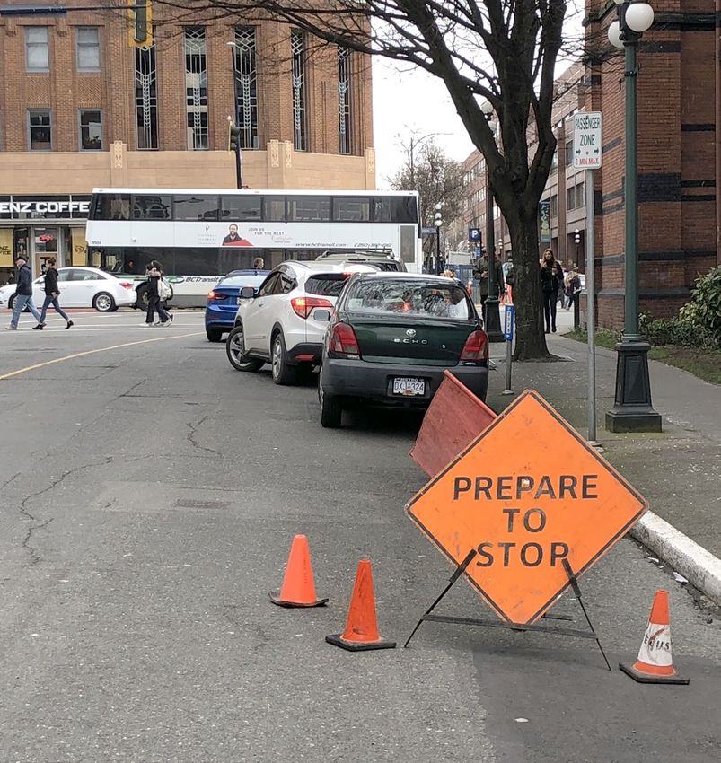
Speed Reader Boards
Description
A speed reader board is an interactive sign that detects and electronically displays the speed of
approaching vehicles. Speed reader boards can be installed permanently on a post/pole adjacent to
a roadway, or temporarily as a portable trailer. Permanent boards are installed where speeding is a
chronic problem, whereas portable boards can be placed in response to requests from the public or
near temporary construction zones.
How it Works Typical Implementation
Speed reader boards are generally placed near a Considerations
regulatory speed limit sign to indicate to motorists
This intervention should be used as a complement,
whether they are respecting or exceeding the
rather than a substitution, for engineering measures.
posted speed limit. They enhance compliance by
Speed reader boards are best used in areas that
drawing drivers’ attention to their speed, and creating
transition to low speeds, and around schools,
the sense that their speed is being monitored.
bikeways, parks, or work zones. Speed reader boards
Some designs flash lights toward vehicles that are
can also be used to help address excessive speeding
exceeding the speed limit in order to draw drivers’
at problem locations. Periodic police speeding
attention to the board. As drivers slow down, their
enforcement should be used to complement this
awareness of pedestrians, cyclists, or of a high-risk
measure. Municipalities should avoid placing boards
area nearby improves.
where they obstruct pedestrian or cyclist travel ways
or sight lines. To avoid provoking street racing, speed
Evidence of Effectiveness reader boards should not display speeds that are well
Speed reader boards have a CRF of 5 to 7% for all in excess of the posted speed limit. Some studies have
crash types and severities on two-lane horizontal shown that speed reader signs can lose effectiveness
curved roadways. There has been little research on overtime as regular road users may begin to ignore
the effects of speed reader boards on speed- the boards.
related crashes. However, studies have shown that
boards generally reduce speeds, with the reductions
varying from significant to small depending on the
application and location of the speed reader board.
For speed reader boards used in school zones, a
Canadian study by Hildebrand and his colleagues
showed a sustained and statistically significant
reduction in the average speeds ranging from 5
to 14 km/h. This reduction was dependent mostly
on the degree of excessive speeding prior to
installation, and on the location within the
school zone. Average speeds where reduced
consistently to a level of approximately 36 km/h
(in a 30 km/h posted zone}.
10B.C. Community ROAD SAFETY TOOLKIT
Module 2: Safe Roadway Designs to Protect All Road Users
Gateways
Description
Gateways, also sometimes known as pinchpoints, are placed on the side of, over, and/or on the road
to provide a visual cue to drivers that they are entering a pedestrianized environment and that they
must reduce their speed. Gateways can include one or more elements such as signs, pavement
markings, coloured road surfacing, physical restrictions (e.g., street narrowing, medians, speed
humps, and curb extensions), over-road structures (portal/arch, artificial or tree canopy), flagpole
arrangement, and special lighting. Gateways can also include other streetscape treatments such
as benches, different streetlights, and sidewalks, which are meant to indicate a changed or more
urban environment.
How it Works Several examples of cities that implemented gateway
treatments can be found in the Pedestrian Safety
Gateways have a short-term effect on speeds, and
Guide and Countermeasure Selection System.
their effect depends on a combination of the gateway
Some of these projects included implementation
itself and road conditions downstream. They are
of several traffic calming measures along a corridor
typically used to indicate a transition from a rural to an
such as speed humps, corner extensions, medians,
urban environment, a change from a higher-speed to
and chicanes, and found that both speeds and traffic
lower-speed environment, or to signify an approach
volumes decreased, while the number of pedestrians
into a village, neighborhood, traffic-calmed area,
using a corridor increased.
downtown, and/or main street. A gateway design that
motorists perceive as a lower speed environment can
be self-enforcing, meaning that it may be effective
Typical Implementation
even without intensifying police enforcement. Considerations
However, enforcement still remains one of the most The effectiveness of gateways in reducing speeds
effective countermeasures for improving road safety. can weaken 250m after passing a gateway, and
therefore careful consideration must be given to
Evidence of Effectiveness conditions and countermeasures downstream from
Simple visual gateways such as signs and pavement the treatment. In general, effective designs include
markings have been found to reduce speeds by a combination of horizontal and vertical treatments,
up to 3%, while more elaborate combination of and should consider the needs of motorists, large
treatment with physical features have been found to commercial vehicles, pedestrians, and cyclists.
reduce speeds by up to 27%. A report by the United The United Kingdom Department of Transport design
Kingdom Department of Transport found that the suggestions state that gateways should be visible
implementation of gateways reduced speeds by 6 over at least the stopping sight distance for the 85th
to 7mph (9 to 11 km/h), and reduced 85th percentile percentile approach speed, visually linked to the start
speeds by as much as 10 mph (16 km/h). of the village, and be at least 5 to 10m long.
According to the CMF Clearinghouse, gateways have a Examples of gateway design considerations,
CRF of 32% for all crashes. Another report documented effectiveness on speed reduction, recommended
a CRF of 55% for fatal plus serious injury crashes, and a practices and guidelines can also be found in the
CRF of 19% for all injury crashes. Traffic Calming Measures report prepared by the
Research in Alberta found a reduction in serious injuries Northern Ireland Department of Transport.
and fatalities of between 25 to 50% at treatment sites
on suburban and rural high speed areas.
11B.C. Community ROAD SAFETY TOOLKIT
Module 2: Safe Roadway Designs to Protect All Road Users
Transverse Rumble Strips
Description
Transverse rumble strips consist of grooves pressed across the traveled portion of a roadway, which
create sound and vibration as drivers passes over them. This alerts drivers of a potential roadway
hazard or a change in environment. Transverse rumble strips have several applications where a
required stop is important, such as in advance of toll booths, ferry terminals, or rail-road crossings.
Transverse rumble strips can be used on the approach to an intersection where it is important that
vehicles on a minor road stop before crossing a major highway, and in the transition zones to highly
pedestrianized areas.
How it Works Typical Implementation
A rumble strip is a road safety feature that is Considerations
implemented to alert motorists of a potential danger.
Transverse rumble strips should only be used in
The most common use of this measure is shoulder
locations where there is a potential for drivers to miss
and centreline rumble strips that alert a motorist that
an important stop condition or when driver fatigue
are drifting out of a travel lane. In contrast, a transverse
is known to be a problem. Over-use of transverse
rumble strip is a rumble strip that is installed across
rumble may cause driver frustration and can cause
the lane to warn drivers of a STOP (or slowdown)
other detrimental issues (e.g., there can be significant
condition ahead. The rumble strips provide a tactile
noise generated when a vehicle travels over a rumble
vibration and audible rumbling that is effective to
strip which may be a problem in built-up
alert the driver of the need to respond to a potential
residential areas).
safety hazard.
Evidence of Effectiveness
Transverse rumble strips have a CRF of 36% for serious
and minor injury crashes. A study of the effectiveness
of transverse rumble strips by the United States Federal
Highway Administration found that transverse rumble
strips were associated with an increase in crashes that
result in damage to vehicles or objects, but decreases
in injury crashes.
12B.C. Community ROAD SAFETY TOOLKIT
Module 2: Safe Roadway Designs to Protect All Road Users
Safe Intersection Design
Intersections are complex environments with a great deal of potential for
conflicts between road users, which may lead to crashes. The intersection
designs and strategies contained in this section focus specifically on improving
intersections to make them safer for all road users.
13B.C. Community ROAD SAFETY TOOLKIT
Module 2: Safe Roadway Designs to Protect All Road Users
Prohibiting Right-turn on Red
Description
In British Columbia, and most of Canada and the United States, laws that were largely put into effect
in the 1970s allow drivers to make a right-turn-on-red (RTOR) unless signage specifically indicates
that this is prohibited. This is not the case in most of Europe where most default laws prohibit the
RTOR. Prohibiting the right-turn on red at signalized intersections lessens simultaneous road user
movements, reducing all types of intersection conflicts and crashes.
How it Works Evidence of Effectiveness
Where RTOR is permitted, drivers must look for No CRFs were found for prohibiting RTOR.
pedestrians crossing from the left and right, for cyclists However, restricting RTOR has a CRF of 7% for all
approaching from the rear, while simultaneously trying crashes, CRFs between -69% and -108% for vehicle/
to find a gap in the vehicle and cyclist stream crossing pedestrian crashes of all severities, and CRFs between
the intersection from the left. This is a highly complex -69% and -82% for vehicle/pedestrian crashes.
scenario requiring high driver workload and greater A review and analysis of literature by Paul Zador found
risk of driver error. With a site-specific prohibition on that the RTOR increases all right-turning crashes by
RTOR, drivers can only proceed to turn right on green. about 23%, vehicle-pedestrian crashes by about 60%,
By separating road users from one another through and vehicle-cyclist crashes by about 100%.
time, this strongly reduces the likelihood of conflict
between road users.
14B.C. Community ROAD SAFETY TOOLKIT
Module 2: Safe Roadway Designs to Protect All Road Users
Convert Two-way Stop Control to All-way Stop Control
Description
The appropriate form of traffic control is a critical factor for ensuring intersection safety. The conversion
of a two-way stop control intersection to an all-way stop control (also known as a four-way stop
control) will help to reduce and/or prevent crashes at intersections, especially at locations with a high
proportion of side and frontal impact crashes, which can often be highly severe. Furthermore, the
relatively low cost and ease of implementation makes this intervention highly attractive.
How it Works Typical Implementation
All-way stop control can reduce right-angle crashes Considerations
and turning crashes at unsignalized intersections
Many believe that, in order to be effective, all-way
by: creating more orderly movements; by reducing
stop controlled intersections should have nearly
speeds for through and turning vehicles; and by
equal traffic volumes on all approaches.
minimizing problems associated with any sight-
However, some studies have also shown that this
distance restrictions.
measure can be very effective even with unbalanced
traffic volumes. Considerations of whether to
Evidence of Effectiveness implement a two-way or all-way stop control should
This measure has a CRF of 71% for all injury crashes, therefore be specific to each implementation site.
and a CRF of 39% for vehicle-pedestrian crashes. The all-way stop control should be implemented
A study by Lovell and Hauer found that the at a location that creates a reasonable expectation
conversion to an all-way stop control is likely to for drivers to have an all-way stop and thus avoid a
reduce the total number of crashes by 47%, and situation where drivers feel they are being asked to
injury crashes by as much as 71%. Another recent stop for no apparent reason, which may lead to
study found that the effectiveness of all-way stop poor driver behaviours (e.g., non-compliance to the
control was increased by the use of additional stop control). Each intersection should have a TAC
signing, including: oversized stop signs; dual warrant assessment completed to ensure that an all-
stop signs; advanced warning signs; “stop ahead” way control is appropriate.
pavement markings; stop bars; fluorescent markers
on stop signs; and overhead or sign-mounted
flashing beacons.
15B.C. Community ROAD SAFETY TOOLKIT
Module 2: Safe Roadway Designs to Protect All Road Users
Advance Traffic Signal Warning Lights
Description
Advance Traffic Signal Warning Lights typically consist of davit-mounted warning signs with two
alternating flashing signal heads. The flashers are used to warn drivers approaching a traffic signal that
the lights will be changing from green to yellow. The signs are installed in advance of an intersection
in order to allow drivers traveling at the posted speed limit sufficient time to come to a safe and
controlled stop.
How it Works The signs are warranted based on one or more of
the following criteria:
Advance warning flashers are timed to activate a
certain number of seconds prior to the traffic signal ¡¡ The legal speed limit on the highway is 70 km/hr
turning yellow. Drivers who have not yet passed the or higher;
flashers when they are activated are made aware that ¡¡ View of the traffic signals at the intersection is
they do not have enough time to reach and cross the obstructed due to a sharp horizontal curve prior
intersection, and must therefore begin to slow down. to the intersection, to the extent that the safe
This improves predictability for drivers, and reduces stopping sight distance is insufficient;
the risk of drivers braking abruptly. The distance of the
¡¡ There is a grade approaching an intersection
signs from the traffic signal stop line is defined by the
sufficient to require a greater than average braking
speed limit and the approach grade.
effort; and
¡¡ Drivers are exposed to many kilometres of high
Evidence of Effectiveness
speed driving before encountering the first signal
Results from a study of 106 signalized intersections of a community in a location where signals might
in British Columbia indicated that crash frequency be unexpected.
at intersections with advance-warning flashers have
a lower frequency of crashes than similar locations
without flashers. The results were not statistically
significant at the 95% confidence level. Benefits were
found primarily for moderate-to-high traffic volumes
on the minor approach.
Typical Implementation
Considerations
The use and application of Advance Warning Flashers
in British Columbia is outlined in Section 400 of the
BC Ministry of Transportation and Infrastructure of BC
Electrical and Traffic Engineering Manual.
16B.C. Community ROAD SAFETY TOOLKIT
Module 2: Safe Roadway Designs to Protect All Road Users
Roundabout Design for Cyclists and Pedestrians
Description
A roundabout is an alternative to a conventional intersection, and consists of a circulatory roadway
where road users must yield to other traffic before entering. Roundabouts are highly effective in
reducing fatality and injury crashes for motor vehicle occupants. However, unless properly designed,
they can increase the risk of crashes for cyclists.
A bicycle path physically separated from the circulating carriageway is preferable. It can be a shared
path of sufficient width and appropriately marked to accommodate both cyclists and pedestrians
around the perimeter of the roundabout. The cycle path should approach the entry and exit legs at
right angles where signed and marked crossings are provided.
How it Works ¡¡ The approach arms should be aligned toward
the middle of the central island, rather than
Roundabouts are generally superior to conventional deflected to the left. This forces vehicles to enter
intersections because they reduce vehicle speed, the roundabout at a right angle, which causes
reduce the number of conflict points where crashes drivers to slow down;
have the potential to happen, and simplify right-of way
assignment. Older designs of roundabouts have the ¡¡ At single-lane roundabouts like pedestrians,
potential to decrease safety for cyclists because they cyclists should be spatially separated from the
placed the cyclists on the outside edge of the roadway in traffic. On the approach to the roundabout ramps
an effective “blind spot” as drivers are focusing on looking allow access/egress from a dedicated or shared-
for vehicles in the centre of the roadway. use pedestrian/cycle facility that surrounds the
roundabout. With lower vehicle speeds in the
To ensure safety, particularly of pedestrians and roundabout confident and able cyclists may
cyclists, the following design elements should choose to travel through the roundabout with the
be considered: other vehicles, however, they should be directed
by the placement of road markings “sharrows”
¡¡ The design speed should be 30 km/h or less and signs to position themselves in the centre
to reduce the kinetic energy and the speed of the lane on the approach and throughout
differential between all road users as this reduces the roundabout;
the number and severity of crashes;
¡¡ At multi-lane roundabouts, due to higher
¡¡ Pedestrian/cycle crossings should be located speeds, more conflict points, and greater overall
at least one car length outside of the entrances/ complexity, it is recommended that the cyclists are
exists of the roundabout to provide a location for directed to use the spatially separated facility; and
vehicles to wait without blocking the circulatory
roadway and providing direct sight lines between ¡¡ A Landscaping buffer should be provided
vehicles and crossing users. The crossings on each between the sidewalk/shared-use facility and
approach should be offset from one another in a circulatory roadway. This buffer will provide
similar fashion to the Offset Crosswalk (see Module 1 better delineation of the sidewalk for the visually
– Protecting People Walking and Cycling), such that impaired, will deter pedestrians from crossing to
pedestrians are directed to face motor traffic before the central island, and will provide space for sign
completing the second stage of their crossing. The installations. The landscaping and vegetation should
addition of pedestrian activated Flashing Amber be designed such that sight lines to pedestrians
Warning Lights can also draw driver’s attention to the are unobstructed.
presence of pedestrians;
17B.C. Community ROAD SAFETY TOOLKIT
Module 2: Safe Roadway Designs to Protect All Road Users
Roundabout Design for Cyclists and Pedestrians continued
Evidence of Effectiveness
Pedestrian Safety
The United States Federal Highway Administration found that converting unsignalized intersections
roundabouts has a CRF of 27% for vehicle-pedestrian crashes. Analysis of pedestrian safety at roundabouts
in Ontario revealed that pedestrian collision rates are lower at roundabouts than at signalized intersections
with comparable traffic and pedestrian volumes. Giuffre and Grana include a review of previous studies on
roundabouts and pedestrian safety, which provide consistent evidence that injury crash risks for pedestrians
are less at roundabouts than at conventional intersections.
Table 1: Pedestrian Crash Rates by Intersection Category
Source: Henderson, R., and Button, N. (2013). Pedestrian Safety in Roundabouts. Paper presented at the 2013 Conference
of the Transportation Association of Canada, Road Safety Strategies for Vulnerable Road Users Session.
Cyclist Safety Typical Implementation
A number of studies have found that some Considerations
roundabouts increase the risk of injury for cyclists.
Other than the above features, considerations need
The Irish National Cycle Manual states that bicycle
to be made to accommodate the various types of
lanes should not be placed inside the roundabout.
road users expected to use the roundabout, such as
children, the elderly, and the hearing-impaired.
This means that municipalities should consider
ensuring things such as safe crosswalks and
reduced crossing distances.
18B.C. Community ROAD SAFETY TOOLKIT
Module 2: Safe Roadway Designs to Protect All Road Users
Eliminating and Redesigning Slip Lanes
Description
Slip lanes (also known as right-turn channels, with the corners islands sometimes referred to
colloquially as pork chops) are separated lanes at intersections that allow right-turning vehicles to
enter a cross street without passing through the intersection. This intersection design includes a
raised concrete island, which pedestrians must reach as a first stage of crossing the intersection.
Slip lanes reduce drivers’ awareness of crossing pedestrians because they are led to focus on the
traffic stream into which they are merging, and also impair visibility of the traffic stream because
of the angle of approach. The design increases crash risks by encouraging faster speeds during a
complex manoeuvre. Slip lanes also greatly increase crossing complexity for pedestrians and
cyclists, by increasing total crossing distance, requiring judgement about crossing fast-moving
traffic without the benefit of a traffic signal, and potentially requiring several signal phases to
complete the crossing. Slip lanes may discourage these active modes of transportation.
Pork chops islands can have significant impact on capacity, which may or may not have an
adverse impact on safety.
This measure works best by eliminating the slip lane and regularizing the intersection to classic
perpendicular crossing geometry. A compromise may be to redesign slip lanes so that vehicles
enter the cross street at a sharper angle (typically 70°). The latter measure is known as the “Urban
Smart Channel.” This measure is best accompanied by a raised crossing across the slip lane to
clarify right-of-way and slow right-turning vehicles.
How it Works Evidence of Effectiveness
Eliminating slip lanes obliges drivers to pass through No CRFs were found for this measure. Research on slip
the intersection to execute the right-turn, resulting lanes has documented substantial risks to pedestrians
in reduced travel speeds, improved driver awareness at intersections, particularly with high-speed turns.
of crossing pedestrians or cyclists, and improved Evidence to date about smart channel design with
driver sight lines of the traffic stream approaching a 70° angle of entry into the intersection points to a
from the left. CRF of 56.3% reduction in overall collisions, based on
Reconstructing slip lanes along the “Urban Smart a Full-Bayes analysis.
Channel” concept forces vehicles to enter the
cross street at a sharper angle. This reduces the Typical Implementation
turning radius, which causes drivers to slow down Considerations
to complete the turn. The sharper entry angle also
There may be concerns about accommodating large
means that more of the intersection and cross street
vehicles if a slip lane is removed and smaller turning
is within the driver’s immediate cone of vision.
radii implemented. However, intersection designs
As a result, the driver does not need to do a sharp
have often overlooked the “effective” turning radius,
left shoulder check, which simplifies the turn.
which can be greater than the corner radius if the
Finally, this layout also positions crossing pedestrians
right-turning lane is not immediately adjacent to
more directly in the line of sight of oncoming
the face of the curb (for example, where there are
vehicles, which increases their visibility to drivers.
parking spaces). Newer engineering practices determine
the effective radius by measuring the actual path that
vehicles may follow into receiving lanes.
19B.C. Community ROAD SAFETY TOOLKIT
Module 2: Safe Roadway Designs to Protect All Road Users
Eliminating and Redesigning Slip Lanes continued
Where the Urban Smart Channel is used, the following design features should be included
to improve safety:
¡¡ Controlled slip lanes (i.e., vehicles must yield to cross traffic, no dedicated exit lanes), combined with raised,
painted crosswalks over the slip lane with warnings and pedestrian activated signals to encourage yielding
to pedestrians. Flashing overhead crosswalk signs can be particularly effective;
¡ Small compound radius turn with an angle of at least 70°. Avoid a constant radius slip lane with
shallow exit angles;
¡ Larger, raised “pork chop” island with cut-throughs/ramps (for bicycles, wheelchairs, mobility
scooters) and good road lighting; and
¡ Crosswalks located 6 metres/one car length in front of where vehicles merge.
20B.C. Community ROAD SAFETY TOOLKIT
Module 2: Safe Roadway Designs to Protect All Road Users
Left-turn Lanes and Signalization
Description
Left-turn bays, or lanes, are “auxiliary” lanes used for the deceleration and queuing of left-turning vehicles.
Signalized left-turns at intersections are installed where warrants (i.e., criteria) are met to provide a dedicated
signal phase for left-turning vehicles. These signals may or may not make use of auxiliary lanes.
During the “protected” left-turn phase, all opposing traffic and conflicting pedestrian traffic is stopped.
How it Works Typical Implementation
Left-turn bays and signalized left-turns reduce Considerations
potential for conflict by separating road users
Operationally, the addition of a left-turn lane can
through space and time. The auxiliary lane reduces
increase the capacity of the intersection by separating
crash risk by separating left-turning vehicles from
left-turn traffic from the through-traffic stream.
following through-traffic meaning that the following
This can enable municipalities to implement shorter
vehicles will not manoeuvre to change lanes in the
signal cycle lengths, and thus improve safety for
attempt to pass the turning vehicle ahead.
pedestrians (see the measure adequate signal
Signalized left-turns give left-turning vehicles an crossing times and signal cycle lengths).
opportunity to complete the turn without the risk
The use of warrants and guidelines are essential for
of confronting opposing through-traffic, or striking
left-turn lanes and left-turn signalization to ensure
pedestrians that are traversing the cross-street
that all factors are considered for the overall safety
and operational performance of the intersection.
Evidence of Effectiveness Guidelines for installation and design of left-turn
Implementing a protected left-turn phase has a CRF lanes in Canada is provided by the Transportation
of 16 to 17% for fatal, serious injury, and minor injury Association of Canada (TAC), Geometric Design Guide
crashes. A combined protected/permitted left-turn for Canadian Roads. Guidelines related to left-turn
phase with a left-turn bay at high-speed intersections signalization can be obtained from the TAC/ITE
has a CRF of 34% for all crashes. Canadian Capacity Guide for Signalized Intersections.
Dedicated left-turn lanes can be further improved by
including a “positive offset.” This measure separates
left-turn lanes from the adjacent same-direction
through-lane, thus lining up the opposing left-
turn lanes. This addresses a situation involving two
opposing left-turning vehicles that obstruct one
another’s view of adjacent through-traffic. See the
document “Provide Offset to Left-turn Lanes” in the
Technical Resources for a diagram of a positive offset.
21B.C. Community ROAD SAFETY TOOLKIT
Module 2: Safe Roadway Designs to Protect All Road Users
Right-turn Lanes at Intersections
Description
Right-turn lanes are curbside lanes that separate the movements of through-traffic from vehicles
wishing to turn onto a cross street.
How it Works Typical Implementation
Right-turn lanes at intersections improve safety by Considerations
separating and significantly reducing the conflicts
Right-turning vehicles potentially increase the risk
between right-turning vehicles and the following
to cyclists in any situation because of cyclists’ small
through-traffic. They may help to make the
size and vulnerability. To reinforce the right-of-way
environment more predictable for all road users
for cyclists, cycling lanes should be positioned to
the left of the right-turn lane. Coloured bicycle lanes
Evidence of Effectiveness on the intersection approach can help draw drivers’
There are numerous CRFs for right-turn lanes at attention to the presence of cyclists. Specific attention
intersections. Municipalities may refer to the CMF should be paid to the geometry of cycling lanes and
Clearinghouse by searching the term “install right- right-turn lanes (see NACTO’s discussion on ‘Through
turn lane” and determine which CMF/CRF best fits Bike Lanes” in the Technical Resources).
the profile of the proposed implementation sites.
The following CMFs apply:
¡¡ 96% all collisions (3-leg i/s one approach);
¡¡ 96% all collisions (4-leg i/s two approach); and
¡¡ 92% all collisions (4-leg i/s all approach).
22B.C. Community ROAD SAFETY TOOLKIT
Module 2: Safe Roadway Designs to Protect All Road Users
Reduced Access Point Density in the Vicinity of Intersections
Description
The functional area of an intersection extends upstream and downstream from the physical area
of an intersection. Access points within this functional area include private and business driveways, as
well as minor or side-street intersections. These access points have the potential to increase the
complexity and unpredictability of the road environment.
How it Works A minimum distance of 80 metres can be assumed for
the application of this safety countermeasure in the
Access points located within 80 metres upstream
absence of a more detailed analysis.
or downstream of an intersection are undesirable
because this area already requires a high level of Ideally, an access management program exists to
driver care and attention. Closing or relocating access carefully manage the access approval process and
points to a location outside this functional area helps achieve balance between land development plans and
reduce the number of decisions motorists must preservation of the functional integrity of the functional
make while travelling through an intersection, and area of intersections.
improves safety in the vicinity of an intersection. Opportunities to reduce access can vary
significantly from site to site, and may include:
Evidence of Effectiveness ¡¡ Converting an access strip to an access point;
CRFs for all crashes can be calculated using ¡¡ Closing redundant accesses;
the formula on page 92 of the BC Ministry of
¡¡ Consolidating multiple accesses into a single new
Transportation and Infrastructure’s Collision
access, which can be achieved by improving
Modification Factors for British Columbia.
circulation between adjoining properties;
These CRFs are for rural stop-controlled intersection.
¡¡ Relocating the access to a corner property from
A CRF for urban intersections was not found;
the main arterial to a collector cross street; and
however, a reduction in rear-end and angle crashes
is expected. ¡¡ Constructing frontage roads.
Typical Implementation
Considerations
The functional area of an intersection includes all
intersection auxiliary lanes and encompasses the
intersection’s perception-reaction-decision distance,
manoeuvre distance, and queue-storage distance.
23B.C. Community ROAD SAFETY TOOLKIT
Module 2: Safe Roadway Designs to Protect All Road Users
Smaller Corner Radii
Description
A corner radius reduction is the reconstruction of an intersection corner that places it further into the
turning lane. The main purpose of a smaller radius is to slow down right-turning vehicles.
How It Works Typical Implementation
Smaller corner radii make the path of a right-turning Considerations
vehicle tighter, which requires a slower speed.
Smaller corner radii can be applied on local and
Slower speeds increase the amount of time that road
collector streets. They may not be effective in very
users have to react to a conflict, reduce the stopping
large intersections because right-turning vehicles
distance in case the driver has to brake, and reduce
might not manoeuvre into the nearest receiving lane.
the kinetic forces in the case of a crash.
They may also not be suitable on routes with large
Intersection corner reconstructions also work to
volumes of buses or trucks, as large vehicles may
position pedestrians further forward before they
need to move into the opposing lane in order to
begin crossing a street, which increases their visibility
negotiate the turn. One possible way to mitigate the
to drivers, and shortens their crossing distance.
risks is by recessing the stop line in the nearest lane of
This is important because corners are where drivers
the receiving street, allowing more room for a large
and pedestrians are most likely to encounter
vehicle to complete the turn.
one another.
In some cases, corner radii reductions through curb
Evidence of Effectiveness extensions may inhibit the installation of bicycle lanes.
Consideration should be given in the planning stages
No CRFs were found for curb radii reductions. to the possibility of bicycle lane construction in
However, smaller curb radii are known to improve the future.
safety, especially for pedestrians and cyclists, at
right-turn locations.
24B.C. Community ROAD SAFETY TOOLKIT
Module 2: Safe Roadway Designs to Protect All Road Users
Safe Corridor Design
The roadway designs described in this section improve safety for all road users
by making physical changes to road corridors that help reduce the likelihood
of driver error and help lessen the consequences to road users when
mistakes happen.
25B.C. Community ROAD SAFETY TOOLKIT
Module 2: Safe Roadway Designs to Protect All Road Users
Continuous Raised Median Barriers
Description
A continuous raised median barrier is any non-traversable physical barrier installed down the middle
of a roadway. It may be used to prevent left-turns, or to prevent deadly cross-over head-on crashes
caused by one vehicle moving into the path of opposing traffic.
Raised medians can be composed of modular concrete barriers, raised curbs with landscaping in
the middle, or a wide space with grass, gravel, sand, or other material.
How it Works Typical Implementation
Installation of a continuous raised median in an urban Considerations
setting will prevent left-turns in and out of driveways
Installing a continuous raised median barrier is
and minor side-streets, significantly reducing the
generally easier in a rural setting compared to an
number of conflict points along an arterial roadway
urban setting. Often, a more realistic configuration
and leading to fewer crashes.
in an urban setting is to provide openings in the
In a rural setting, a continuous median barrier is median at a few designated locations (e.g., major
very effective at reducing off-road left and head-on access points/intersections). Openings can also be
crashes, which at higher speeds lead to high injury used at the ends of deceleration and storage lanes
crashes for motor vehicle occupants. A median in order to accommodate left-turns off of the arterial
barrier can also have this function on higher speed street and to remove them from the through lanes.
urban roads. Access into some areas will be right-turns only, and
generally access out of developments will be right-
Evidence of Effectiveness turns only. The design of medians requires adequate
Installing a continuous raised median has a CRF of provision for left-turns to avoid over concentrating
22% for fatal and injury crashes on urban multi-lane these movements at individual intersections.
roads, and a CRF of 39% for all crashes on urban
two-lane roads.
26B.C. Community ROAD SAFETY TOOLKIT
Module 2: Safe Roadway Designs to Protect All Road Users
Continuous Centre Two-way Left-turn Lanes
Description
A continuous two-way left-turn lane (TWLTL) is a special shared lane in the centre of a roadway
reserved for mid-block left-turns into or out of driveways or side streets.
How it Works Association of Canada (TAC) Geometric Design Guide
provides a good description of the major factors to
A TWLTL improves safety by separating turning
be considered. Some of these are listed here.
vehicles from through lanes and by providing a
refuge for vehicles entering through lanes from TWLTLs are normally used with 3 and 5 lane cross
access points along a road. sections, with 5 lanes being the most common.
They are best suited for urban roads with operating
speeds of 50 to 60 km/h. A traffic volume of 24,000
Evidence of Effectiveness
vehicles per day is generally recommended; however,
CRFs for all crashes can be calculated using this measure has been successfully implemented
the formula on page 42 of the BC Ministry of for volumes up to 35,000 per day. In some cases a
Transportation and Infrastructure’s Collision TWLTL is achieved by eliminating a parking lane or by
Modification Factors for British Columbia. converting an existing 6 lane road to 5 lanes with a
This CRF only applies on road segments where centre TWLTL and curbside cycling lanes.
the access point density is greater than 3. Arterial roadways with straight flat alignments and
low to moderate volume number of driveways
Typical Implementation represent typical applications.
Considerations TWLTLs are generally not extended through major
Due to the complexity and number of design factors intersections and are not suitable for high
to be considered, each site needs to be examined by volume driveways. A combination of exclusive left-
experienced design and traffic operations personnel turn lanes at high volume driveways and a TWLTL
to determine the improvements required to elsewhere may be feasible if the high volume
successfully implement a TWLTL. The Transportation accesses are well spaced in relation to the
other accesses.
27B.C. Community ROAD SAFETY TOOLKIT
Module 2: Safe Roadway Designs to Protect All Road Users
Drainage
Description
Drainage refers to measures that collect and divert water away from the road surface, and redirect
it to desired locations. A drainage system for a road network typically includes retention devices to
manage flow rates, ditches and catch basins to gather the water, culverts and piping systems to pass
the water under roads, and manholes for maintenance purposes.
How it Works Typical Implementation
Well-designed drainage systems efficiently remove Considerations
water from the road’s surface, which in turn improves
Drainage systems should be designed to control
road safety performance by reducing the likelihood
downstream flooding, maintain base flows in
of hydroplaning for vehicles and improves road
streams to support aquatic life, minimize pollution,
friction, and improves visibility by reducing the
cause minimal siltation in water courses, and be
amount of spray. Adequate drainage also improves
cost effective.
the road environment for pedestrian and cyclist
In addition to being cycle friendly when curbside,
Evidence of Effectiveness avoid locating the catch basin in the ramp area for a
crosswalk/shared-use facility. If unavoidable, ensure
No CMFs were found for this measure. High friction the grate is of a design that will not trap the wheels of
pavement treatments that are deployed to improve wheelchairs, walking aids and buggies or have gaps
drainage have a CRF of 8%, which can be applied to large enough to let a walking cane pass through.
all road types and targets all crash types.
28B.C. Community ROAD SAFETY TOOLKIT
Module 2: Safe Roadway Designs to Protect All Road Users
High Friction Pavement
Description
There are many types of treatments that can be used to improve the surface quality for a road
or highway. Some examples include the application of chemical de-icing, using high-friction
additives to pavement surfaces, the use of porous asphalt composed of larger stones to allow better
drainage, and cutting grooves into the pavements to increase friction and assist in drainage.
How it Works Elvik and Vaa list some CRFs for improved road
surface conditions. For example, anti-icing chemicals
High friction pavement treatments include any
have a CRF of 13%, which can be applied to all
intervention that can help to increase the friction
road types and target all crash types. High friction
between a vehicle’s tires and the road surface.
pavement treatments that are deployed to improve
An improved level of friction helps drivers to better
drainage have a CRF of 8%, which again can be
steer the vehicle, improves stopping control, and helps
applied to all road types and targets all crash types
prevents loss of control. This is especially the case in
rainy or wet conditions. High friction pavements are
typically used on the approach to intersections,
Typical Implementation
locations with challenging horizontal and vertical Considerations
alignment (e.g., sharp curves or steep grades), or at Some high-friction pavement treatments can be
locations where the road surface quality is poor or costly, and due to the added wear and tear caused by
weather conditions are frequently problematic. increased friction, may need to be repaired more often.
Porous asphalt also reduces water spray from As such, the location for the use of these types of
vehicles, which improves visibility for drivers in interventions should be limited to higher-priority
rainy weather. locations first to ensure cost-effective results.
Some studies have found that improvements in road
Evidence of Effectiveness friction were accompanied by greater evenness of
The road safety engineering literature is somewhat the road surface, which in turn resulted in slightly
limited in the details related to specific treatments, higher speeds. As part of efforts to improve surface
but a general CRF for improvements to road surface friction, municipalities may consider implementing
treatments is provided for guidance. Some judgement other measures for reducing speeds.
may be required to select a CRF that accurately reflects
the effectiveness of the high friction pavement
treatment in relation to typical, non-treated road
surface and recognizing that there is considerable
variability in the effectiveness of high-friction
road surface treatments.
29You can also read