Beam Selection Assisted UAV-BS Deployment and Trajectory for Beamspace mmWave Systems
←
→
Page content transcription
If your browser does not render page correctly, please read the page content below
Hindawi
Wireless Communications and Mobile Computing
Volume 2021, Article ID 1363586, 21 pages
https://doi.org/10.1155/2021/1363586

Research Article
Beam Selection Assisted UAV-BS Deployment and Trajectory for
Beamspace mmWave Systems

          Xingxuan Zuo,1 Jiankang Zhang ,2 Sheng Chen,3 and Xiaomin Mu1
          1
            School of Information Engineering, Zhengzhou University, Zhengzhou 450001, China
          2
            Department of Computing & Informatics, Bournemouth University, BH12 5BB, UK
          3
            School of Electronics and Computer Science, University of Southampton, SO17 1BJ Southampton, UK

          Correspondence should be addressed to Jiankang Zhang; jzhang3@bournemouth.ac.uk

          Received 8 August 2021; Accepted 7 September 2021; Published 30 September 2021

          Academic Editor: Xingwang Li

          Copyright © 2021 Xingxuan Zuo et al. This is an open access article distributed under the Creative Commons Attribution License,
          which permits unrestricted use, distribution, and reproduction in any medium, provided the original work is properly cited.

          Exploiting unmanned aerial vehicles (UAVs) as base stations (UAV-BS) can enhance capacity, coverage, and energy efficiency of
          wireless communication networks. To fully realize this potential, millimeter wave (mmWave) technology can be exploited with
          UAV-BS to form mmWave UAV-BS. The major difficulty of mmWave UAV-BS, however, lies in the limited energy of UAV-
          BS and the multiuser interference (MUI). Beam division multiple access with orthogonal beams can be employed to alleviate
          the MUI. Since each user has dominant beams around the line of sight direction, beam selection can reduce the power
          consumption of radio frequency chain. In this paper, we formulate the problem of maximizing the sum rate of all users by
          optimizing the beam selection for beamspace and UAV-BS deployment in the mmWave UAV-BS system. This nonconvex
          problem is solved in two steps. First, we propose a signal-to-interference plus noise ratio-based greedy beam selection scheme
          to ensure that all the ground users in the given area can be served by the UAV-BS, where a zero forcing precoding scheme is
          used to eliminate the MUI. Then, we utilize the continuous genetic algorithm to find the optimal UAV-BS deployment and
          beam pattern to maximize the sum rate of all users. Moreover, considering the mobility of the UAV-BS, the UAV-BS
          trajectory and beam selection for beamspace are optimized in the mmWave UAV-BS system. The simulation results
          demonstrate the effectiveness of the proposed design for the mmWave UAV-BS system.

1. Introduction                                                              In the first category, UAVs are considered aerial quasi-
                                                                         stationary BSs. The altitude and horizontal positions of
Unmanned aerial vehicles (UAVs) have drawn growing atten-                UAVs can be separately or jointly optimized to obtain a bet-
tion in a wide range of applications, such as disaster rescue,           ter air-ground channel for meeting different requirements of
surveillance and monitoring, aerial imaging, and cargo delivery          ground users [7–9]. Specifically, in [7], the altitude of the
[1, 2]. Wireless communication utilizing UAVs is a promising             UAV-BS was optimized to achieve the maximum coverage
technology to achieve fast deployment and flexible reconfigura-            for the terrestrial users. By contrast, with the fixed altitude,
tion [3, 4]. Specifically, UAVs as different types of wireless             the horizontal placement of UAV-BS was jointly optimized
communication platforms, such as UAV base stations                       with the user association in [8]. Furthermore, the joint opti-
(UAV-BS), aerial relays, and UAV swarms, assist and enhance              mization of altitude and horizontal positions of UAV-BS
terrestrial communications [5, 6]. Employing UAV-BS in par-              was investigated in [9], where the aim of the UAV-BS place-
ticular is a cost-effective solution to assist the existing terrestrial   ment is to maximize the number of covered users with min-
communication infrastructure by providing seamless coverage              imum transmit power.
and improving the network performance. Recent researches on                  For the second category, UAVs are considered mobile BSs.
UAV-BS can be divided into two main categories.                          By exploiting the mobility of UAV-BS, the communication
2 Wireless Communications and Mobile Computing
distance between the UAV-BS and terrestrial users can be channel [24]. To exploit the sparsity of the beamspace channel,
significantly shortened via careful design on the trajectory of beam selection was investigated in [25] to achieve near-
UAV-BS. In [10], a joint optimization of the UAV-BS trajec- optimal performance with fewer RF chains. In [26], a compar-
tory and transmit power for multiple users was developed to ison among different kinds of beam selection schemes was
dynamically establish short-distance line of sight (LoS) links evaluated, in terms of the required number of RF chains as
and thus to improve the throughput of the system. A joint well as the trade-off between spectral efficiency and energy
optimization of the UAV-BS trajectory and user scheduling efficiency. Furthermore, the power allocation for BDMA
for a UAV-enabled secure system was proposed in [11] to transmission was analyzed in [27] with only statistical channel
maximize the minimum secrecy rate under the required state information (CSI). In [28], considering the power leakage
constraints of UAV-BS and ground users. In [12], a joint and the imperfect channel statistics estimation, the RF chains
optimization of the UAV trajectory and nonorthogonal multi- were further reduced after the beamspace transformation in
ple access (NOMA) precoding was investigated for a UAV- the lens antenna array.
assisted NOMA network, where the UAV trajectory and There exist increasing interests in the use of the genetic
NOMA precoding are jointly optimized to maximize the sum algorithm (GA) for wireless communication and signal
rate of users served by the UAV-BS and NOMA-network BS. processing [29–31], since GA can attain the global optimal
Early researches mainly focused on the UAV-BS work- solutions of challenging optimization problems with affordable
ing in microwave frequencies with a single antenna owing computational complexity and it does not require derivative
to the strict constraint of size. Because the UAV-BS also information [32]. The work [31] applied several evolutionary
has limited on-board energy, the signals of a single antenna algorithms, including continuous GA (CGA), to solve the diffi-
may be significantly attenuated due to the long communica- cult problem of joint channel estimation and turbo multiuser
tion distance between the UAV-BS and ground users [13]. detection/decoding. Compared with discrete GA [32], CGA
However, by exploiting the small wavelengths of millimeter has high precision, low storage, and high speed without the
wave (mmWave) signals, mmWave frequencies can be requirement of prior decoding. In [33], GA was utilized to find
adopted to the UAV-BS to pack large antenna arrays in the optimal deployment of drones to cover the target area with
small dimensions [14, 15]. the lowest cost. However, the method of [33] is based on the
The combination of UAV-BS and mmWave communica- single transmit antenna, which can be improved by taking the
tion technology therefore offers advantages of enhancing cov- multiple transmit antennas and MUI into account.
erage, improving energy efficiency, and providing sufficient The comparison of the recent researches in UAV-BS and
bandwidth [16]. An UAV-BS mmWave system can naturally BDMA is summarized in Table 1. Inspired by the existing
establish LoS links between UAV-BS and ground users to research, we focus on the mmWave UAV-BS system, where
support the connectivity of existing ground wireless networks the mmWave-frequency antenna array and DLA are employed
[17]. Because of limited scattering of air-to-ground links in the by the UAV-BS to direct signals to different directions and to
mmWave band, the path loss is dominant by LoS. The authors form the beamspace channel. We propose a beam selection
of [18] developed a 3D beamforming approach to achieve effi- optimization for beamspace and UAV-BS deployment to max-
cient and flexible coverage in mmWave UAV-BS communica- imize the sum rate of all ground users. Due to the sparse nature
tions. In [19], the impact of adaptive navigation on mmWave of the beamspace channel in BDMA, the dominant beams are
UAV-BSs was investigated to enhance the system performance. near the LoS directions of the ground users. By properly
Furthermore, the mmWave UAV-BS deployment optimiza- designing the horizontal positions of the mmWave UAV-BS,
tion is an important issue to improve the performance. In not only can the better channel gain be achieved but also the
[20], the optimized mmWave UAV-BS deployment, which interfering channel distance among the ground users can be
includes the optimal height, horizontal coordinates, and cover- enlarged to alleviate the MUI, while imposing lower number
age radius, was analyzed by taking into account human body of RF chains. However, this design problem is nonconvex
blockage. Xiao et al. [21] presented a mmWave UAV-BS and difficult to solve directly. To tackle this challenging optimi-
deployment optimization with a constant modulus beamform- zation problem, we decompose it into two subproblems by first
ing to maximize the sum rate of all ground users. However, designing the beam selection scheme for beamspace and then
since mmWave UAV-BSs place large antenna arrays in a small finding the optimal positions and beam pattern of the
area, the power consumption of radio frequency (RF) chains is mmWave UAV-BS. For the first subproblem, we propose a
considerable [22], but UAV-BSs typically have limited energy signal-to-interference plus noise ratio- (SINR-) based greedy
supply. In addition, to support simultaneous transmissions beam selection scheme. When the UAV-BS communicates
between the mmWave UAV-BS and ground users, the multi- with its served users, if the served users have different dominant
user interference (MUI) mitigation is necessary. beams, the UAV-BS will naturally select their corresponding
Since mmWave UAV-BS signals propagate mainly through dominant beams. However, in the scenario that two or more
LoS paths, users from different directions can be simultaneously users have the same dominant beam, the UAV-BS can select
served by orthogonal beams, which is known as beam division the beams to users according to the SINR-based greedy beam
multiple access (BDMA) [16]. By employing orthogonal beams, selection scheme. Zero forcing (ZF) precoding is used to fur-
MUI can be effectively decreased to improve the system perfor- ther eliminate the MUI. Given the SINR-based greedy beam
mance [23]. In particular, the discrete lens array (DLA), which selection, we design a CGA to solve the second subproblem,
points signals in different directions, was employed in BDMA namely, the optimal deployment of the mmWave UAV-BS
to transform the conventional spatial channel into a beamspace system. Similarly, considering the mobility of the mmWaveWireless Communications and Mobile Computing 3
Table 1: Reference comparison of recent researches.
[7] [8] [9] [10] [11] [12] [18] [20] [21] [25] [26] [28] [33]
2016 2019 2017 2018 2018 2019 2019 2018 2020 2016 2015 2018 2019
UAV-BS √ √ √ √ √ √ √ √ √
Deployment √ √ √ √
3D deployment √ √ √ √
Trajectory √ √ √
mmWave √ √ √ √ √
Beamforming √ √ √ √ √
BDMA √ √ √
ZF √ √ √
Beam selection √ √ √
SINR √ √ √
Multiuser √ √ √ √ √ √ √ √ √ √ √ √
Multiuser interference √ √ √
GA √
UAV-BS, we also optimize the trajectory of the mmWave pose operators are denoted by ð·ÞT and ð·ÞH , respectively. The
UAV-BS by the CGA scheme, given the SINR-based greedy inverse operation is denoted by ð·Þ−1 , while trð·Þ represents the
beam selection. The main contributions of this paper are trace operation. The operator A \ B denotes the set consisting
recapped below. of all elements in A excluding those in B. The integer ceiling
operation is denoted by d·e, 0K is the K-dimensional zero vec-
(1) In this paper, we consider a mmWave UAV-BS, tor, and IK is the ðK × KÞ-dimensional identity matrix, while
which is equipped with the lens antenna array to Aði, :Þi∈I denotes the submatrix consisting of the rows of A
serve the multiple ground users. Aimed at maximiz- with the row indices given by the index set I . The cardinality
ing the sum rate of all ground users, the optimization of the set I is denoted by ∣I ∣ , and the jth element of I is
problem of beam selection and UAV deployment is denoted as I ðjÞ, while w ðk,:Þ and w ð:,kÞ denote the kth row
complicated to solve, which is decomposed into
two subproblems and kth column of W, respectively.
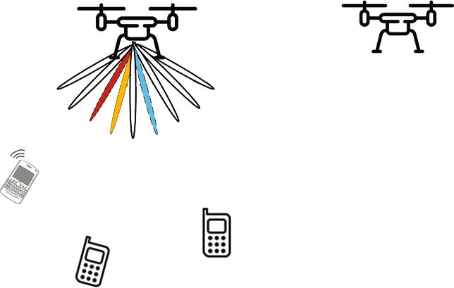
(2) First, we propose an SINR-based greedy beam selec- 2. System Model and Problem Formulation
tion scheme for the users which share the same
dominant beams, where ZF precoding is employed As illustrated in Figure 1, we consider an mmWave downlink
to further minimize the MUI. Then, the CGA of multiuser communication system, where a rotary-wing UAV-
UAV-BS deployment is designed to optimize the BS employs N t transmit antennas and N RF RF chains to simul-
UAV deployment and beam pattern by maximizing taneously communicate with K terrestrial users. The different
the sum rate of ground users users are served by different beams. Each ground user is
equipped with a single antenna, and the horizontal coordinate
(3) We also formulate an optimization problem of beam
of the kth ground user is given by uk = ½xk yk T ∈ ℝ2×1 , 1 ≤ k
selection and UAV-BS trajectory in the multiuser
≤ K. We assume that the UAV-BS flies at a constant altitude
mmWave system to maximize the sum rate of all
H (m) above the ground and the location of UAV-BS pro-
ground users with the speed constraint of UAV-BS.
jected on the ground in the 3D rectangular coordinate system
Given the suboptimal SINR-based greedy beam
selection, the CGA-based mmWave UAV-BS trajec- is defined by q = ½qx qy T ∈ ℝ2×1 .
tory optimization is proposed
2.1. Channel Model. Owing to the flexibility of the UAV-BS,
The paper is structured as follows. Section 2 introduces the the LoS can be naturally established in low-altitude plat-
system model and problem formulation. The optimizations of forms [34], and scattering is relatively rare in mmWave
beam selection in beamspace as well as mmWave UAV-BS frequencies for the air-to-ground links. Thus, we assume
deployment and trajectory are addressed in Section 3. The that the wireless links between the UAV-BS and the ground
design analysis and achievable performance are provided users are dominant by the LoS paths [18, 35]. Then, the
and discussed in Section 4. Section 5 concludes the paper. effective channel model between the UAV-BS and the kth
In this paper, ℝ and ℂ denote the real and complex num- ground user can be expressed as [36]
ber fields, respectively. The boldfaced lowercase and uppercase
letters stand for vectors and matrices, respectively. ∥·∥ denotes
the Euclidean norm, while the transpose and Hermitian trans- hk = βk aðθk Þ, ð1Þ4 Wireless Communications and Mobile Computing
Forward 2.1.2. UAV-BS Trajectory. To take into account the mobile
direction nature of the UAV-BS, the UAV-BS trajectory should be
considered. Specifically, the fly-hover communication proto-
col [39] of rotary-wing UAV-BS can be adopted to realize
the communication with users. The UAV-BS serves the
ground users with a constant mission time T, which can be
equally divided into N + 1 time slots. For this fly-hover
u1 = (x1, y1)T uK = (xK, yK)T communication protocol, the UAV-BS successively visits
User 1 User K the N optimized hovering locations and communicates with
the ground users when it is hovering at the optimized loca-
User 2
u2 = (x2, y2)T
tions. Since the UAV-BS flies at a constant altitude H, the
horizontal coordinate in the nth time slot is defined as q½n
= ½qx ½nqy ½nT , n = 0, 1, ⋯, N + 1. In practice, the trajectory
Figure 1: A mmWave UAV-BS serving multiple ground users.
of the UAV-BS should satisfy the following constraints:
8
where aðθk Þ ∈ ℂN t ×1 is the array steering vector of the kth >
> q½0 = qI , q½N + 1 = qF ,
>
<
ground user and βk is the gain of the LoS path for this
A tra = kq½n + 1 − q½nk ≤ vmax , 0 ≤ n ≤ N, ð5Þ
ground user. The channel coefficient βk depends on the path >
> h i
>
: q½n ∈ qx,l , qx,h × qy,l , qy,h ,∀n,
loss at the mmWave frequency and is given by [37, 38]
1 where qI , qF ∈ ℝ2×1 denote the initial and final horizontal
βk = α , ð2Þ
4πf m,m × 109 /c · dk L locations of the UAV-BS, respectively, and vmax is the max-
imum speed of the UAV-BS, that is, the UAV-BS velocity
qffiffiffiffiffiffiffiffiffiffiffiffiffiffiffiffiffiffiffiffiffiffiffiffiffiffiffiffiffi v ≤ vmax , while ½qx,l , qx,h × ½qy,l , qy,h denotes the UAV-BS fly-
where d k = H 2 + kq − uk k2 is the distance between the
ing area. The forward direction vector of the UAV-BS is
UAV-BS and the kth ground user, c = 3 × 10⁸ m/s is the related to the location of the next time slot and is defined
speed of light, f m,m is the carrier frequency, and αL is the as q f ½n = ½ðqx ½n + 1 − qx ½nÞðqy ½n + 1 − qy ½nÞ0T , n = 0, 1,
parameter of the LoS path loss model. In our investigation,
⋯, N. Thus, the spatial direction of the kth user at the nth
f m,m = 28 GHz is allocated and αL = 0:95 is adopted. In addi-
time slot can be expressed as
tion, the spatial direction θk is defined as θk = cos ðϕk Þ,
where ϕk is the real angle of departure of the kth ground h i
user. Hence, the range of θk is ½−1, 1. A uniform linear array ½xk yk 0 − qx qy H · q f ½n
θk,n = h iT : ð6Þ
(ULA) is employed in the mmWave UAV-BS, and the array
½xk yk 0T − qx qy H ∥·∥q f ½n
steering vector for the kth ground user is expressed as [26]
h d 1−N t N t −1 d N t −1
iT
aðθk Þ = e−j2πλð 2 Þθk ⋯ e−j2πλðl− 2 Þθk ⋯ e−j2πλð 2 Þθk , l = 0, 1, ⋯N t − 1,
d
2.2. Beamspace Representation. By employing an elaborately
designed DLA, the traditional channel (1) in the spatial
ð3Þ domain can be translated into an equivalent one in the
beamspace or angular domain [40]. In particular, let U ∈
where λ is the signal wavelength and d = λ/2 is the antenna ℂN t ×N t be the spatial discrete Fourier transform (DFT)
element spacing. matrix representing the operation of the DLA, which is
2.1.1. UAV-BS Deployment. For the mmWave UAV-BS acquired by the steering vectors at the N t fixed spatial
deployment, the spatial direction of the kth user θk is related frequencies with uniform spacing [41, 42]. Thus, the DFT
to the placement of the UAV-BS, given as the cosine value of matrix U, which contains the N t orthogonal beams that
the direction vector from the kth ground user to the UAV- cover the whole space, is defined as
BS and the UAV-BS forward direction vector ½100T [21]. 1 h i
Thus, the spatial direction θk is defined as U = pffiffiffiffiffi aðψ1 Þaðψ2 Þ ⋯ a ψN t , ð7Þ
Nt
h i
½xk yk 0 − qx qy H · ½100T where ψn = 1/N t ðn − ððN t + 1Þ/2ÞÞ, n = 1, 2, ⋯, N t , are the
θk = h iT predefined spatial directions. The DFT matrix U forms the
½xk yk 0T − qx qy H ∥·∥½100T
basis of the N t -dimensional spatial orthogonal signal space.
ð4Þ Let x ∈ ℂK×1 be the transmitted symbol vector to the K
x k − qx
2 ffi:
= rffiffiffiffiffiffiffiffiffiffiffiffiffiffiffiffiffiffiffiffiffiffiffiffiffiffiffiffiffiffiffiffiffiffiffiffiffiffiffiffiffiffiffiffiffiffiffiffiffiffiffiffiffiffi ground users and y ∈ ℂK×1 be the received signal vector at
ð x k − qx Þ + y k − qy + H
2 2 the K ground users. Then, the system model in the beamspace
domain can be expressed asWireless Communications and Mobile Computing 5
~ H Wx + n,
y=H ð8Þ ~ is a function of the
Note that the beamspace channel H
UAV-BS position q, and hence, B also depends on q as well
where n ~ CN ð0k , σ2n IK Þ is the additive white Gaussian noise as the way of beam selection. Therefore, Rsum depends on
(AWGN) vector with the covariance matrix σ2n IK , W ∈ ℂN t ×K both q and B, and the UAV-BS placement problem in the
~∈ beamspace domain can be formulated as
is the precoding matrix, and the beamspace channel H
ℂ N t ×K
is defined as
max Rsum ðq, BÞ,
q,B
~ = ½hb,1 hb,2 ⋯ hb,K = ½Uh1 Uh2 ⋯ UhK = UH, ð14Þ
H ð9Þ s:t: q ∈ Adep :
where H ∈ ℂN t ×K is the spatial channel for all the K users and
2.3.2. UAV-BS Trajectory Problem Formulation. The UAV-
hb,k ∈ ℂN t ×1 is the beamspace channel of the kth user. The
BS trajectory problem is to determine the mission trajectory
beamspace channel H ~ indicates that the signals of each user
fq½ngNn=0 ∈ A tra of the UAV-BS. At the nth time slot, given
are mapped in the N t orthogonal beams, and each element ~ is
of hb,k denotes one of the N t beams supported by the DLA. the UAV-BS position q½n, the beamspace channel H
known. Let B½n be the corresponding selected beam set.
2.3. Problem Formulation In order to study the performance of the UAV-BS trajectory,
we consider the sum rate of the kth user served by the UAV-
2.3.1. UAV-BS Deployment Problem Formulation. Let the BS in the nth time slot of a mission, which is expressed as
UAV hovering area A dep be defined by
0
~H ½nw ~ 2
B h r ð:,kÞ ½nk
qx,l ≤ qx ≤ qx,u , qy,l ≤ qy ≤ qy,u , ð10Þ Rk ½n = log2 @1 + ðPt1 /K Þ
2
r ðk,:Þ
σn + ðPt1 /K Þ∑Kj=1, j≠k
h~H ½nw ~
r ðk,:Þ
2
r ð:, jÞ ½nk ,
where qx,l and qy,l denote the minimum values of qx and qy , ð15Þ
respectively, while qx,u and qy,u represent the maximum
values of qx and qy , respectively. The UAV-BS deployment where h ~
r ðk,:Þ ½n is the reduced beamspace channel vector of
problem is to determine the position q ∈ A dep to deploy the kth user in the nth time slot, Pt1 denotes the transmit
the UAV-BS. Due to the sparse nature of the beamspace power at the UAV-BS for each time slot, and w ~ r ð:,kÞ ½n is
channel [24], there are only a few dominant entries of the the reduced precoding vector of the kth user in time slot n.
beamspace channel for each user. The use of the beamspace Therefore, the sum rate for all the users over the N + 1 time
channel allows us to select the corresponding beams to
slots can be expressed as Rsum,N = ∑Kk=1 ∑Nn=0 Rk ½n.
reduce the dimension of the mmWave UAV-BS system
Based on the above discussion, we can formulate the sum
without significant performance loss. The reduced system
rate maximization problem for the UAV-BS trajectory as
model in the beamspace domain is given by
~H max Rsum,N fq½ngNn=0 , fB½ngNn=1 ,
~y = H r Wr x + n, ð11Þ fq½ngNn=0 ,fB½ngNn=1
~
~ r = Hðb, s:t: fq½ngNn=0 ∈ A tra :
where H :Þb∈B and B consists of the indices of the
selected beams, while Wr is the precoding matrix with the ð16Þ
corresponding reduced dimension. Thus, the received signal
at the kth user can be expressed as fB½ngNn=1 depends on the UAV-BS trajectory fq½ngNn=1
and how the beams are selected at each time slot n.
K
~H w~
~yk = h ~H
r ð:,kÞ xk + 〠 hr ðk,:Þ w r ð:, jÞ x j + nk ,
~
r ðk,:Þ ð12Þ 3. Solution of the Problem
j=1, j≠k
By evaluating the Hessian matrices of the objective functions
where ~yk is the kth element of ~y . Based on the above discus- for the problems (14) and (16), it can be seen that both the
sion, for the UAV-BS transmission with multiple users, the optimization problems are nonconvex and highly complex.
average achievable rate of the kth user is Therefore, it is challenging to solve the problems (14) and
0 (16) by the existing optimization tools. We focus on the
~H w~ 2 optimization problem of UAV-BS deployment first by sepa-
h r ð:,kÞ k
Rk = log2 B r ðk,:Þ
@1 + ð P /K Þ rating the problem (14) into two subproblems. The “inner”
2
σn + ðPt /K Þ∑Kj=1, j≠k
t
h~H w~ k2
, subproblem determines the selected beam set B giving the
r ðk,:Þ r ð:, jÞ
UAV-BS position q. A suboptimal SINR beam selection
ð13Þ algorithm is introduced to incrementally maximize the
sum rate of the mmWave UAV-BS system. With this SINR
where Pt is the total transmission power of the UAV-BS. beam selection scheme, the “outer” subproblem then solves
Thus, the sum rate of all the users is Rsum = ∑Kk=1 Rk . the UAV-BS deployment by employing the CGA algorithm.6 Wireless Communications and Mobile Computing
Next, we solve the optimization problem (16) for UAV-BS ⋯,N t g \ BG N . Let BG O denote the selected beams for the
trajectory in a similar way. Specifically, the CGA is designed overlap users in G O .
to optimize the UAV-BS trajectory with the proposed The precoding matrix Wr for all the users with the
suboptimal SINR beam selection scheme. selected beams Bsel = BG O ∪ BG N can be expressed as
3.1. Beam Selection. Given the UAV-BS position q, the
~ is known. The proposed SINR beam Wr = αFr , ð18Þ
beamspace channel H
selection scheme is composed of two parts. The ground users
having unique dominant beams can select the dominant where α is the power normalization factor given by
beams to communicate with the UAV-BS, while the users sffiffiffiffiffiffiffiffiffiffiffiffiffiffiffiffiffi
having overlap dominant beams will search for the proper P
α= t , ð19Þ
beams from the unselected beams by incrementally maxi- tr Fr FH r
mizing the SINR of the mmWave UAV-BS system, where
ZF is utilized to further eliminate the MUI.
Due to the sparse structure of the beamspace channel in and Fr is the ZF precoding matrix expressed as
the mmWave UAV-BS system, the beamspace channel for H −1
the kth user has dominant values near the LoS direction Fr = H ~r H
~r H ~r , ð20Þ
[25]. Since the dominant beams have the most transmission
power, they can be selected for the transmission to reduce
in which H ~
~ r = Hðb, :Þb∈Bsel . The SINR with the ZF precoding
the number of RF chains with minor performance loss. In
order to reduce the number of RF chains N RF to the mini- for user k can be expressed as [44]
mum, we consider that each user is served by only one beam,
and hence, N RF = K. Let the index of the selected dominant Pt jαj2
SINRk,Z F = : ð21Þ
beam for user k be Bmax,k , which is defined as [43] Kσ2n
2
Thus, the maximization of the SINR can be transformed
Bmax,k = i⋆ = arg max hib,k , ð17Þ to the maximization of the normalization factor α with
1≤i≤N t
respect to the selected beam set BG O for the overlap users
in G O .
where hib,k denotes the ith element of the kth column of the Hence, we can select the required beams for the overlap
~ users in G O one by one based on a greedy-type beam selec-
beamspace channel H.
tion algorithm that identifies the beams with the maximal
Given the beamspace channel vectors hb,k and the corre-
gains in terms of SINR. Specifically, at each selection stage,
sponding selected beam indexes (17) for 1 ≤ k ≤ K, the K
a beam is selected for an overlap user in G O which maxi-
users can be assigned into the two groups, the nonoverlap
mizes the gain in the SINR. This greedy beam selection
group G N and the overlap groups G O . The group G N
algorithm is summarized in Algorithm 1.
includes the users having the unique dominant beams, while
a user in the group G O has the same selected beam with 3.2. Continuous Genetic Algorithm for UAV-BS Deployment.
some other users in G O . In particular, the selected beam For given q, we use Algorithm 1 to select the beam set
set or index of a nonoverlap user i satisfies Bmax,i ∩ Bdep ðqÞ = Bsel ðqÞ. Express the objective function of the
ð∪ j≠i,1≤j≤K Bmax, j Þ = ∅. On the other hand, if Bmax,i ′ ∩ UAV-BS deployment problem for this beam selection
ð∪ j≠i ′ ,1≤j≤K Bmax, j Þ ≠ ∅, the i ′ th user is an overlap user scheme as f dep ðqÞ = Rsum ðq, Bdep ðqÞÞ. Hence, with this
and is assigned to G O . Obviously, G N and G O satisfy greedy SINR-based beam selection scheme, the optimization
G N ∪ G O = f1, 2,⋯,Kg and G O ∩ G N = ∅. We consider an of the UAV-BS deployment can be expressed as
example of K = 6 and N t = 8, where Bmax,1 = f1g, Bmax,2 =
f4g, Bmax,3 = f7g, Bmax,4 = f7g, Bmax,5 = f8g, and Bmax,6 q⋆ = arg max f dep ðqÞ: ð22Þ
q∈A dep
= f8g. Then, G N = f1, 2g and G O = f3, 4, 5, 6g.
For nonoverlap user k ∈ G N , the beam with index Bmax,k We propose to apply the CGA [30, 45, 46] to solve this
will be directly selected, since this dominant beam contains optimization problem. With Pdep denoting the population
most of the transmission power and causes few interferences size and g being the generation index, the procedure of the
to other users. Let BG N denote the selected beams for the CGA-based UAV-BS deployment is detailed below.
nonoverlap users in G N . For the overlap users in G O , the
beams should be reselected to communicate with the (1) Initialization: at g = 0, the initial population of Pdep
UAV-BS by maximizing the sum rate of all users. To incre- chromosomes or candidate UAV-BS locations
mentally maximize the sum rate, the beams which result in
fqg,p gPp=1
dep
are randomly generated over the UAV
the maximum increase in SINR should be selected. In order
to mitigate the MUI with the user group G N , the beams for hovering area A dep . Algorithm 1 is utilized to select
the users in G O are selected from the beam set BR = f1, 2, the beam set Bdep ðqg,p Þ for every chromosome qg,pWireless Communications and Mobile Computing 7
lest fitness has the lowest probability of mating. Let Pdep
m be
~ Bmax,k for 1 ≤ k ≤ K
Input: H, the probability of selecting the mth chromosome for mating
Output: Bsel , H ~r from the Pkeep,d chromosomes, which is calculated as
1: for k = 1 ⟶ K
2: if Bmax,k ∩ ð∪k ′ ≠k,1≤k ′ ≤K Bmax,k ′ Þ = ∅ Pkeep,d − m + 1
3: k ∈ GN Pdep
m = P
, 1 ≤ m ≤ Pkeep,d : ð23Þ
4: else ∑m=1
keep,d
m
5: k ∈ GO
6: end Then, Pdep dep
m is turned into the cumulative probability P c,m
7: BG N = ∩ k∈G N Bmax,k
for deciding which chromosome can be selected as a parent.
8: BG O = ∅ In particular, when a random number Pmum between 0 and 1
9: BR = f1, 2,⋯,N t g \ BG N dep
is generated, if Pc,m−1 < Pmum ≤ Pdep c,m , the mth chromosome
10: forj ′ = 1 ⟶ K − jG N j
will be selected as a parent (mum). For instance, let Pkeep,d
11: j = ff1, 2,⋯,Kg \ G N gðj ′ Þ
12: for i ′ = 1 ⟶ jBR j = 4, and the corresponding Pdep m ∈ f0:4,0:3,0:2,0:1g. Then,
13: i = BR ði ′ Þ Pdep
c ,m ∈ f0:4,0:7,0:9,1g. If P mum = 0:33, the first chromosome
14: ~
CðiÞ = Hðb, :Þb∈ðBG ∪BG ∪iÞ is selected as “mum.” Similarly, the “dad” chromosome is
H
N
−1
O
chosen in the same manner. We adopt two parents produc-
15: FðiÞ = C i
qððC
ðiÞ
Þ CðiÞ Þ
ffiffiffiffiffiffiffiffiffiffiffiffiffiffiffiffiffiffiffiffiffiffiffiffiffiffiffiffiffiffiffiffi ing two offspring as a common form of mating. Thus, Pdep
16: αðiÞ = Pt /trðFðiÞ ðFðiÞ Þ Þ
H
− Pkeep,d parents are required for mating to create new
17: end offspring. We will assume that Pdep − Pkeep,d is an even num-
2
18: i⋆j = arg max jαðiÞ j ber, and we have selected ðPdep − Pkeep,d Þ/2 pairs of parents.
∀i
19: BG O = BG O ∪ i⋆j
20: BR ⟵ BR \ BR ði⋆j Þ (3) Crossover: each pair of parents selected for the cross-
21: end
over operation can be expressed as
22: Bsel = BG O ∪ BG N
~ r = Hðb,
23: H ~ :Þb∈Bsel
8 h iT
>
>
< qg,mum = qx,g,mum qy,g,mum ,
h iT ð24Þ
Algorithm 1: Greedy SINR-based beam selection. >
>
: qg,dad = qx,g,dad qy,g,dad :
They are used to produce two offspring qg,os1 and qg,os2 .
, and then, the fitness value F depg,p = f dep ðqg,p Þ is
calculated, for 1 ≤ p ≤ Pdep . The Pdep chromosomes The single crossover point scheme is utilized to combine
the parents’ information. A crossover point qpc is randomly
are ranked from top to bottom according to their
fitness values. Denote this ranked population as selected between x and y. If y is selected as the crossover
fqg,p ; F depg,p gPdep with the fitness values F depg,1 ≥ point, i.e., qpc = y, the two new offspring are produced as
p=1
F depg,2 ≥ ⋯≥F depg,P 8 h iT
>
>
< qg,os1 = qx,g,mum qpc ,g,os1 ,
dep
(2) Selection: set g = g + 1. The Pkeep,d previous h iT ð25Þ
>
>
chromosomes with the highest fitness values will : qg,os2 = qx,g,dad qp ,g,os2 ,
c
survive into the next generation, i.e.,
fqg,p = qg−1,p ; F depg,p = F depg−1,p gPkeep,d , and these with
p=1
high-fitness chromosomes also form a mating pool, 8
where Pkeep,d = Pdep · γdep is the size of the mating >
< qpc ,g,os1 = qpc ,g,mum − μ qpc ,g,mum − qpc ,g,dad = qy,g,mum − μ qy,g,mum − qy,g,dad ,
pool. The selection ratio γdep decides how many
>
:q
pc ,g,os2 = qpc ,g,dad + μ qpc ,g,mum − qpc ,g,dad = qy,g,dad + μ qy,g,mum − qy,g,dad ,
chromosomes are to be chosen for the mating pool
from the total Pdep chromosomes. The mating pool ð26Þ
is used to select parents to provide Pdep − Pkeep,d
offspring for the next generation to maintain a where μ is a random value uniformly selected in the range of
constant-size population ð0, 1Þ. Similarly, if x is selected as the crossover point, i.e.,
qpc = x, the crossover operation produces the two corre-
The rank weighting, a roulette wheel weighting [30], is sponding offspring from the pair of parents.
used to choose chromosomes for mating. With this weight- Algorithm 1 selects the beam set for every offspring, and
ing, the chromosome with the largest fitness has the greatest its fitness value is calculated. After the crossover, the new
probability of mating, while the chromosome with the smal- generation of the chromosomes include the Pkeep,d elitist8 Wireless Communications and Mobile Computing
chromosomes from the previous generation and their Pdep where the objective function of the UAV-BS trajectory prob-
− Pkeep,d offspring. These Pdep chromosomes are ranked lem is f tra ðqN Þ = Rsum,N ðqN , Btra ðqN ÞÞ. We also apply the
from top to bottom according to their fitness values as CGA to solve this optimization problem. From (27), each
fqg,p ; F depg,p gPdep . chromosome has 2N coordinates, and the pth chromosome
p=1 in the gth generation can be expressed as
(4) Mutation: the element qpm ,g,p of chromosome qg,p is n oN h
randomly selected to mutate; thereby, the mutated qN g,p = qg,p ½n = qx,g,p ½1qy,g,p ½1qx,g,p ½2qy,g,p ½2 ð29Þ
n=1
element is replaced by a new random value qpm ,l ≤
qpm ,g,p ≤ qpm ,u , where pm = x or y, while 2 ≤ p ≤ Pdep . iT
We opt to not mutate the best chromosome with ⋯ qx,g,p ½N qy,g,p ½N :
the highest fitness found so far, i.e., qg,1 . The number
of elements that will mutate in each generation is With the population size Ptra , the procedure of the CGA
governed by a mutation probability M dep [45, 46]. for the UAV-BS trajectory is now detailed.
Thus, the total number of mutated elements is 2ð
Pdep − 1ÞM dep since each chromosome has 2 ele- (1) Initialization: at g = 0, the initial population of Ptra
ments. The mutation operation is crucial to provid- chromosomes fqN g,p gPtra is randomly generated,
p=1
ing sufficient diversity for the CGA
constrained inside A tra . Algorithm 1 then selects
Algorithm 1 then selects the beam sets for the mutated the beam sets fBtra ðqN g,p ÞgPtra , and the correspond-
p=1
chromosomes, and their fitness values are calculated. After-
ing fitness values fF trag,p = f tra ðqN g,p ÞgPtra are calcu-
ward, the mutated population of the Pdep chromosomes is p=1
ranked again from top to bottom according to their fitness lated. Then, these Ptra chromosomes are ranked
values as fqg,p ; F depg,p gPdep . from top to bottom according to their fitness values
p=1
as fqN g,p ; F trag,p gPtra with the fitness values F trag,1 ≥
p=1
(5) Termination: if g > Gmax,dep , where Gmax,dep is the F trag,2 ≥ ⋯≥F trag,P
tra
maximum number of generations, the procedure
stops and the chromosome with the highest fitness (2) Selection: set g = g + 1, and retain the Pkeep,t previous
is chosen as the solution, i.e., q⋆ = qg,1 . Otherwise, chromosomes with the highest fitness values in the next
the procedure repeats from step (2) generation as fqN g,p = qN g−1,p ; F trag,p = F trag−1,p gPkeep,t ,
p=1
which also form a mating pool, where Pkeep,t = Ptra ·
The CGA-based UAV-BS deployment algorithm is sum-
marized in Algorithm 2. The population size Pdep , the max- γtra with γtra being the selection ratio. As usual, the
mating pool is used to select parents to provide Ptra
imum number of generations Gmax,dep , the selection ratio
− Pkeep,t offspring for the next generation to maintain
γdep , and the mutation probability M dep are the problem-
a constant-size population
dependent algorithmic parameters, which need to be care-
fully chosen. The rank weight is also adopted to select parents from
3.3. Continuous Genetic Algorithm for UAV-BS Trajectory. the mating pool. The probability Ptra
m of the mth chromo-
With the initial and final locations qI and qF fixed, the some to be selected from the mating pool is again defined by
UAV-BS trajectory has N locations, which is expressed as
Pkeep,t − m + 1
T
Ptra
m = P
, 1 ≤ m ≤ Pkeep,t , ð30Þ
qN = qT ½1qT ½2 ⋯ qT ½N : ð27Þ ∑m=1
keep,t
m
For given q½n at time slot n, we use Algorithm 1 to select and Ptra tra
m is converted into the cumulative probability Pc,m to
the beam set Btra ðq½nÞ = Bsel ðq½nÞ. Denote the overall choose chromosomes as parents from the mating pool.
beam set selected for qN by Algorithm 1 as Btra ðqN Þ =
fBsel ðq½nÞgNn=1 . Then, the optimization of the UAV-BS tra- (3) Crossover: the mating strategy with two parents pro-
jectory is reduced to ducing two new offspring is utilized, and hence, a
total of ðPtra − Pkeep,t Þ/2 pairs of parents are selected.
q⋆N = arg max f tra ðqN Þ, ð28Þ A generic pair of two parents selected from the
qN ∈A tra mating pool can be expressed asWireless Communications and Mobile Computing 9
8 h iT
>
>
< qN g,mum = qx,g,mum ½1qy,g,mum ½1 ⋯ qx,g,mum ½nqy,g,mum ½n ⋯ qx,g,mum ½N qy,g,mum ½N ,
h iT ð31Þ
>
>
: qN = qx,g,dad ½1qy,g,dad ½1 ⋯ qx,g,dad ½nqy,g,dad ½n ⋯ qx,g,dad ½N qy,g,dad ½N :
g,dad
Input: A dep , Pdep , γdep , Gmax,dep , M dep
Output: q⋆ , Bdep ðq⋆ Þ
1: Set g = 0, randomly generate Pdep chromosomes qg,p ∈ A dep , determine Bdep ðqg,p Þ with Algorithm 1, and calculate fitness values
F depg,p , for 1 ≤ p ≤ Pdep
2: Rank Pdep chromosomes according to their fitness values from top to bottom as fqg,p ; F depg,p gPdep
p=1
3: Pkeep,d = Pdep · γdep
4: while g ≤ Gmax,dep
5: g=g+1
6: fqg,p ; F depg,p gPkeep,d = fqg−1,p ; F depg−1,p gPkeep,d
p=1 p=1
P
m = P keep,d − m + 1/∑m=1 m, Pm ⟶ P c,m , 1 ≤ m ≤ P keep,d
Pdep keep,d dep dep
7:
8: for i = 1 ⟶ Pdep − Pkeep,d /2
9: Select pair of parents with Pdep
c,m from mating pool
10: Use single-point crossover to generate two offspring
11: Calculate their beam sets and fitness values
12: end for
13: Rank Pkeep,d survivals and Pdep − Pkeep,d offspring according to their fitness values from top to bottom as fqg,p ; F depg,p gPdep
p=1
14: for p = 2 ⟶ Pdep
15: Mutate qg,p with mutation probability M dep
16: If mutated, re-calculate beam set and fitness value
17: end for
18: Rank mutated population according to their fitness values from top to bottom as fqg,p ; F depg,p gPdep
p=1
19: if g > Gmax,dep
20: q⋆ = qg,1 , Bdep ðq⋆ Þ = Bdep ðqg,1 Þbreak
21: end if
22: end while
Algorithm 2: Continuous GA for UAV-BS deployment.
2rffiffiffiffiffiffiffiffiffiffiffiffiffiffiffiffiffiffiffiffiffiffiffiffiffiffiffiffiffiffiffiffiffiffiffiffiffiffiffiffiffiffiffiffiffiffiffiffiffiffiffiffiffi
2 3
The number of crossover points depends on the UAV-BS 2
flying area ½qx,l qx,h × ½qy,l qy,h and the maximum speed con-
6 qx,h − qx,l + qy,h − qy,l 7
straint vmax . In particular, the longest straight flying distance
qffiffiffiffiffiffiffiffiffiffiffiffiffiffiffiffiffiffiffiffiffiffiffiffiffiffiffiffiffiffiffiffiffiffiffiffiffiffiffiffiffiffiffiffiffiffiffiffiffiffi Nl = 6
6
7 − 1: ð32Þ
7
6 vmax 7
is the diagonal line ðqx,h − qx,l Þ2 + ðqy,h − qy,l Þ2 ; thereby, 6 7
the minimum required number of time slots to fly across the
UAV-BS flying area can be expressed as Thus, the 2N l -point crossover scheme is utilized to10 Wireless Communications and Mobile Computing
guarantee the offspring satisfying the constraints A tra . Spe- until the constraints A tra are met. Given the muta-
cifically, the first crossover point n is randomly selected tion probability M tra , a total of 2M tra NðPtra − 1Þ
from f1, 2,⋯,N − N l + 1g, and the two offspring produced elements will be mutated
can be expressed, respectively, as
The beam sets for the mutated chromosomes are selected
with Algorithm 1, and their fitness values are calculated. The
qN g,os1 = qx,g,mum ½1qy,g,mum ½1 ⋯ qx,g,mum ½n − 1qy,g,mum ½n − 1 mutated population of the Ptra chromosomes is ranked again
from top to bottom according to their fitness values as
qx,g,os1 ½nqy,g,os1 ½nqx,g,os1 ½n + 1 ⋯ qx,g,os1 ½n + N l − 1 fqN g,p ; F trag,p gPtra .
p=1
qy,g,os1 ½n + N l − 1 qx,g,dad ½n + N l qy,g,dad ½n + N l (5) Termination: if g > Gmax,tra , where Gmax,tra denotes
T
the maximum number of generations, the procedure
⋯ qx,g,dad ½N qy,g,dad ½N ,qN g,os2 stops with the solution q⋆N = qN g,1 . Otherwise, the
ð33Þ
= qx,g,dad ½1qy,g,dad ½1 ⋯ qx,g,dad ½n − 1qy,g,dad ½n − 1
procedure repeats from step (2)
This CGA for the UAV-BS trajectory optimization is
qx,g,os2 ½nqy,g,os2 ½nqx,g,os2 ½n + 1 ⋯ qx,g,os2 ½n + N l − 1 summarized in Algorithm 3.
3.4. Complexity Analysis. The complexity of the proposed CGA
qy,g,os2 ½n + N l − 1 qx,g,mum ½n + N l qy,g,mum ½n + N l for the UAV-BS deployment optimization with the aid of the
greedy SINR beam selection algorithm is specified by the num-
⋯ qx,g,mum ½N qy,g,mum ½N T : ber N GA,dep of the cost function evaluations and the complexity
per cost function evaluation. Given the population size Pdep and
Each offspring contains portions of the “genes” from both the maximum number of generation Gmax,dep , we have N GA =
parents. Specifically, offspring os1 has mum’s genes before the Pdep · Gmax,dep , whereas the complexity per cost function is
first crossover point n and dad’s genes after the last crossover
derived according to Rsum and the greedy SINR beam selection
point n + N l − 1, while offspring os2 has dad’s genes before the
algorithm. The complexity evaluations of Rsum and the greedy
first crossover point n and mum’s genes after the last crossover
SINR beam selection algorithm are listed in Table 2.
point n + N l − 1. The new coordinates qx and qy at the cross-
Thus, the complexity of the proposed CGA for the
over points are the combinations of the coordinates from both UAV-BS deployment optimization with the aid of the
parents, which can be expressed as
greedy SINR beam selection algorithm is N GA,dep · fðK − j
8 K−jG j
> G N jÞ∑i=1 N ðN t − jG N j − iÞ½3ðjG N j + iÞ3 + 4ðjG N j + iÞ2 + 1
< qx/y,g,os1 ½nl = qx/y,g,mum ½nl − μ qx/y,g,mum ½nl − qx/y,g,dad ½nl ,
+ 2K 2 + ðN t + 1ÞKg. In a similar way, the number N GA,tra
>
:q of the cost function evaluations of the proposed CGA for
x/y,g,os2 ½nl = qx/y,g,dad ½nl + μ qx/y,g,mum ½nl − qx/y,g,dad ½nl ,
the UAV-BS trajectory optimization with the aid of the
ð34Þ greedy SINR beam selection algorithm is N GA,tra = Ptra ·
Gmax,tra , and the complexity of the proposed CGA for the
for n ≤ nl ≤ n + N l − 1, where μ is a random value uniformly UAV-BS trajectory optimization with the aid of the greedy
selected from ð0, 1Þ. If the new coordinates produced do not SINR beam selection algorithm is N · N GA,tra · fðK − jG N jÞ
satisfy the maximum speed constraint of A tra , μ is reselected K−jG j
until the new coordinates meet the requirements of A tra . ∑i=1 N ðN t − jG N j − iÞ½3ðjG N j + iÞ3 + 4ðjG N j + iÞ2 + 1 + 2
The beam set of every offspring is then selected using K 2 + ðN t + 1ÞKg.
Algorithm 1, and its fitness value is calculated. The new gener-
ation of the chromosomes, including the Pkeep,t elitist chromo- 4. Performance Analysis
somes from the previous generation and their Ptra − Pkeep,t We evaluate the performance of the proposed CGA for the
offspring, is ranked from top to bottom according to their fit- UAV-BS deployment optimization and the proposed CGA
ness values as fqN g,p ; F trag,p gPtra . for the UAV-BS trajectory optimization, with the aid of the
p=1
greedy SINR beam selection algorithm. We consider an
(4) Mutation: the chromosomes qN g,p , 2 ≤ p ≤ Ptra , are UAV-BS simultaneously serving several (K) ground users in
a mmWave system. The terrestrial users are randomly distrib-
subject to random mutation with the mutation prob- uted in the square area of ½0,100 × ½0,100 (m2), and the UAV-
ability M tra to explore other area of A tra so as to
BS deployment area/flying area is also this ½0,100 × ½0,100
avoid local maxima. Specially, 2N l points of a chro- (m2) square area. The main default parameters of this simu-
mosome, qx,g,p ½n, qy,g,p ½n, ⋯, qx,g,p ½n + N l − 1, qy,g,p lated UAV-BS mmWave system are listed in Table 3.
½n + N l − 1, are randomly chosen to be mutated. If
the mutated chromosome does not satisfy the 4.1. Performance of the CGA for UAV-BS Deployment. We
requirement of A tra , the chromosome is remutated first quantify the performance of the proposed CGA-basedWireless Communications and Mobile Computing 11
Input: A tra , N l , Ptra , γtra , Gmax,tra , M tra
Output: q⋆N , Btra ðq⋆N Þ
1: Set g = 0, randomly generate Ptra chromosomes qN g,p ∈ A tra , determine Btra ðqN g,p Þ with Algorithm 1, and calculate fitness values
F trag,p , for 1 ≤ p ≤ Ptra
2: Rank Ptra chromosomes according to their fitness values from top to bottom as fqN g,p ; F trag,p gPtra
p=1
3: Pkeep,t = Ptra · γtra
4: while g ≤ Gmax,tra
5: g=g+1
6: fqN g,p ; F trag,p gPkeep,t = fqN g−1,p ; F trag−1,p gPkeep,t
p=1 p=1
P
m = P keep,t − m + 1/∑m=1 m, Pm ⟶ P c,m , 1 ≤ m ≤ P keep,t
Ptra keep,t tra tra
7:
8: for i = 1 ⟶ Ptra − Pkeep,t /2
9: Select pair of parents with Ptra c,m from mating pool
10: repeat
11: Randomly generate μ
12: Use 2N l -points crossover to produce two offspring qN g,os1 , qN g,os2
13: until qN g,os1 , qN g,os2 ∈ A tra
14: Calculate beam sets and fitness values of two offspring
15: end for
16: Rank survivals and offspring according to their fitness values from top to bottom as fqN g,p ; F trag,p gPtra
p=1
17: for p = 2 ⟶ Ptra
18: Select qN g,p with probability M tra
19: repeat
20: Randomly mutate 2N l elements of qN g,p
21: until Mutated chromosome satisfies A tra
22: Calculate beam set and fitness value of mutated chromosome
23: end for
24: Rank mutated population according to their fitness values from top to bottom as fqN g,p ; F trag,p gPtra
p=1
25: if g > Gmax,tra
26: q⋆N = qN g,1 , Btra ðq⋆N Þ = Btra ðqN g,1 Þbreak
27: end if
28: end while
Algorithm 3: Continuous GA for UAV-BS trajectory.
Table 2: Complexity in number of operations.
Number of operations
2
hib,k ∀i, k N tK
K−jG N j
F ðK − jG N jÞ〠i=1 ðN t − jG N j − iÞ 3ðjG N j + iÞ3 + 2ðjG N j + iÞ2
K−jG N j
α ðK − jG N jÞ〠i=1 ðN t − jG N j − iÞ 2ðjG N j + iÞ2 + 1
Rsum 2K 2 + K
UAV-BS deployment with the aid of the greedy SINR beam ment is randomly chosen in the square area of ½0,100 ×
selection scheme. ½0,100 m 2 . As expected, the CGA-optimized UAV-BS
Figure 2 depicts the achievable sum rate as the function deployment outperforms the random deployment. In par-
of the number of users for the proposed CGA-optimized ticular, for the system with K = 8 users, the sum rate
UAV-BS deployment, in comparison with the performance attained by the proposed optimized approach is about 5
attained by the random UAV-BS deployment. Both deploy- bits/s/Hz higher than that of the random deployment.
ments are aided by the greedy SINR beam selection. The We also evaluate the achievable sum rates as the func-
system has the total transmission power Pt = 20 dBm. The tions of the transmit power Pt for our CGA-optimized
position of the mmWave UAV-BS in the random deploy- UAV-BS deployment and the random UAV-BS deployment12 Wireless Communications and Mobile Computing
Table 3: Default system parameters.
Parameter Value
Height of UAV-BS H 100 m
Number of transmit antennas at UAV-BS N t 16
Network AWGN σ2n -94 dBm
Frequency f m,m 28 GHz
LoS parameter αL 0.95
Population size Pdep 20
Mutation probability M dep 0.2
UAV-BS deployment
Selection ratio γdep 0.5
Number of generation Gmax,dep 50
Population size Ptra 100
Mutation probability M tra 0.05
Number of time slots N 10
UAV-BS trajectory
Maximum speed of UAV-BS vmax 50 (m/s)
Selection ratio γtra 0.5
Number of generation Gmax,tra 50
70
60
50
Sum rate (bits/s/Hz)
40
30
20
10
1 2 3 4 5 6 7 8
The number of users
Optimized UAV−BS position
Random UAV−BS position
Figure 2: Comparison of achievable sum rates versus number of users for the CGA-optimized deployment and random deployment, both
with the aid of the greedy SINR beam selection, given total transmission power Pt = 20 dBm.
in Figure 3, for the system of K = 4 ground users. Again, the Next, we investigate the convergence performance of the
greedy SINR beam selection is utilized by both deployments. proposed CGA with the aid of the greedy SINR beam selec-
It can be seen that our CGA-optimized UAV-BS deploy- tion for UAV-BS deployment. The system has K = 4 ground
ment outperforms the random deployment by around 8 users with the total transmission power Pt = 20 dBm.
bits/s/Hz. Figure 4 depicts the maximum sum rate and the mean sumWireless Communications and Mobile Computing 13
80
70
60
Sum rate (bits/s/Hz)
50
40
30
20
10
10 15 20 25 30
Pt (dBm)
Optimized UAV−BS position
Random UAV−BS position
Figure 3: Comparison of achievable sum rates versus total transmit power Pt for the CGA-optimized deployment and random deployment,
both with the aid of the greedy SINR beam selection, given K = 4 ground users.
45
44
43
Sum rate (bits/s/Hz)
42
41
40
39
38
0 10 20 30 40 50
Generation
Mean sum rate
Maximum sum rate
Figure 4: Convergence performance of the CGA with the aid of greedy SINR beam selection for optimizing UAV-BS deployment, averaged
over 100 runs. The system has K = 4 ground users and total transmission power Pt = 20 dBm.14 Wireless Communications and Mobile Computing
60
55
50
Sum rate(bits/s/Hz)
45
40
35
30
25
20
15
10 15 20 25 30
Pt(dBm)
proposed beam selection
Conventional beam selection 1−beam
Conventional beam selection 2−beam
Figure 5: Comparison of achievable sum rates versus total transmit power Pt for three beam selection schemes. The system has K = 4
ground users, and the UAV-BS is deployed at the CGA-optimized position.
rate of the population as the function of the number of latter. This is because this MCMS scheme selects the stron-
generations, averaged over 100 independent deployments. gest beam of each user. But some users may share the same
It can be observed from Figure 4 that the CGA converges strongest beam, and hence, this scheme may result in inter-
within 30 generations. ference from selecting the same beams for different users. It
Our greedy SINR beam selection scheme selects one was further observed that the sum rate of the MCMS scheme
beam per user by incrementally maximizing the SINR, and with 2 beams per user is only marginally better than that of
it requires N RF = K RF chains. The maximum channel our greedy SINR selection scheme of 1 beam per user. This is
magnitude selection (MCMS) scheme in [43] is selected as because although utilizing the second strongest beam for
a reference to the proposed greedy SINR beam selection each user is beneficial for enhancing the achievable rate of
scheme. For the MCMS scheme, by calculating the jhib,k j the individual user, some second strongest beams may be
for each beam, m strongest beams can be chosen for each shared by different users too, resulting in the increased inter-
user. To demonstrate its effectiveness, we compare its sum ference. Hence, the performance gain of the MCMS scheme
rate performance versus the system transmit power Pt with by using 2 beams per user is very slight compared with our
those of the MCMS scheme with 1 beam per user and 2 greedy SINR beam selection scheme.
beams per user. Again, the system has K = 4 ground users. In order to see the trade-off between sum rate perfor-
For fair comparison, the CGA-optimized UAV-BS position mance and RF complexity, we need to investigate the trans-
is used for all the three cases. To mitigate MUI and for a fair mit energy efficiency, which is defined by [47]
comparison, the ZF precoding is also employed in the
MCMS scheme. The MCMS scheme chooses the required R
η= ðbits/s/Hz/WÞ, ð35Þ
number of dominant beams for each user, which may result Pt + N RF · PRF
in selecting the same beam for different users. Note that for
the scheme with 2 beams per user, the required RF chains where R (bits/s/Hz) is the sum rate and PRF (W) represents
are N RF = 2K. Figure 5 compares the sum rate performance the power consumed in each RF chain, and PRF = 34:4 mW
of these three beam selection schemes as the functions of is adopted as the practical value [47]. For the same system
the transmission power Pt . Observe that our proposed beam setup as in Figures 5 and 6, compare the energy efficiency
selection scheme, which has 1 beam per user, significantly against the total transmit power Pt achieved by the three
outperforms the MCMS scheme with 1 beam per user. Given beam selection schemes. As observed from Figure 6, the
Pt = 25 dBm, for example, the sum rate of our greedy SINR energy efficiency of the MCMS scheme with 2 beams per
selection scheme is 13 bits/s/Hz higher than that of the user is far inferior to that of its counterpart of 1 beam perWireless Communications and Mobile Computing 15
140
Energy Efficiency (bits/s/Hz/mW)
120
100
80
60
40
10 15 20 25 30
Pt(dBm)
Proposed beam selection
Conventional beam selection 1−beam
Conventional beam selection 2−beam
Figure 6: Comparison of energy efficiency performance versus total transmit power Pt for three beam selection schemes. The system has
K = 4 ground users, and the UAV-BS is deployed at the CGA-optimized position.
380
360
340
320
Sum rate (bits/s/Hz)
300
280
260
240
220
200
180
20 30 40 50 60 70 80 90 100
The number of users
Optimized UAV−BS positions
Random UAV−BS positions
Figure 7: Comparison of achievable sum rates versus number of users for the CGA-optimized deployment and random deployment, both
with the aid of the greedy SINR beam selection, given total transmission power Pt = 20 dBm and N t = 256.
user, except for high Pt situation. Our greedy SINR selection for Pt = 20 dB, although the sum rate of the MCMS scheme
scheme with 1 beam per user significantly outperforms both with 2 beams per user is about 1 bit/s/Hz better than that
MCMS schemes, in terms of energy efficiency. In particular, of our scheme of 1 beam per user, as shown in Figure 5,16 Wireless Communications and Mobile Computing
100
90
straight
Rsum,N = 419.4 bits/s /Hz
80
70
y(m) 60
50 optimized
Rsum,N = 477.1 bits/s /Hz
40
30
20
10
0
0 20 40 60 80 100
x(m)
Optimized UAV−BS trajectory
Straight UAV−BS trajectory
Location of random user
Figure 8: Comparison of the CGA-optimized UAV-BS trajectory and the shortest straight-line UAV-BS trajectory, both with the aid of the
greedy SINR beam selection scheme. The system has K = 4 ground users, and the transmit power per time slot is Pt1 = 20 dBm.
480
470
460
Sum rate (bits/s/Hz)
450
440
430
420
410
400
0 10 20 30 40 50
Generation
Mean sum rate
Maximum sum rate
Figure 9: Convergence performance of the CGA with the aid of greedy SINR beam selection for optimizing UAV-BS trajectory, averaged
over 100 runs. The system has K = 4 ground users, and transmit power per time slot is Pt1 = 20 dBm.You can also read