Bowling Center Operating Procedures - Operations Manual September 2005 / 53-900194-000
←
→
Page content transcription
If your browser does not render page correctly, please read the page content below
Operations Manual

  Bowling Center
Operating Procedures
   September 2005 / 53-900194-000
Bowling Center Operating Procedures Manual

© September 2005 by the Brunswick Bowling and Billiards Corporation. All rights reserved.

Frameworx, Classic, Vector, Vector Plus and GS Pinsetter area registered trademarks of the Brunswick
Bowling and Billiards Corporation.

Reorder Part No. 53-900194-000

Notice: If available, updates to this manual can be found on-line at www.brunswickbowling.com.

All information contained in this document is subject to change without notice.

Brunswick Bowling and Billiards
525 West Laketon Avenue
P.O. Box 329
Muskegon, MI 49443-0329
U.S.A.

231.725.3300

2                                                          Bowling Center Operating Procedures Manual
Contents
Administrative ................................................................................................................................ 4
        TYPICAL MECHANIC’S CLIPBOARD SYSTEM FOR BCOP PROCEDURES .......................                                                                  4
            Mechanic’s Training Program ...................................................................................................              4
            Mechanic’s Training Program Form .........................................................................................                   5
            Service Bulletins ........................................................................................................................   7

Pinsetters ..................................................................................................................................... 10
        GS SERIES PREVENTIVE MAINTENANCE PROGRAM .........................................................10
             Instructions for GS Pinsetters Preventive Maintenance Work Schedule ................................. 11
             GS Pinsetters Preventive Maintenance Work Schedule Form .................................................18
             GS Pinsetters Pending Items Form ..........................................................................................20
             GS Pinsetters Parts Usage Log Form ......................................................................................21
        GS PINSETTERS DAILY STOP RECORDS ..................................................................................22
             GS Series Stop Sheet Form ......................................................................................................23
             GS Series Pinsetter Error Codes Form ....................................................................................24
        GS SERIES PINSETTER WEEKLY FRAMES PER STOP RECORDS .......................................25
             GS Series Pinsetter Weekly Stop Report Form ........................................................................26
        GS SERIES PINSETTER MONTHLY FRAMES PER STOP RECORDS ....................................27
             Universal Monthly Frames Per Stop Record Form ..................................................................28
        CONTROL COUNTER MALFUNCTION REPORT ....................................................................29
             Control Counter Malfunction Report Form ..............................................................................30

Automatic Scorers ....................................................................................................................... 31
        AUTOMATIC SCORER PREVENTIVE MAINTENANCE SCHEDULE ..................................31
            Automatic Scorer Preventive Maintenance Schedule Form ....................................................32

Lanes ............................................................................................................................................ 33
        LANE PREVENTIVE MAINTENANCE SCHEDULE ................................................................33
            General Lane Maintenance Schedule ......................................................................................34
            Lane Preventive Maintenance Schedule Form ........................................................................35

Bowling Equipment - Product Trouble Report and Warranty Policy ........................................ 36
        BRUNSWICK PRODUCT TROUBLE REPORT ..........................................................................36
            Product Trouble Report Form ..................................................................................................38
            Universal Date Codes Form ....................................................................................................39
            Error Codes Form ....................................................................................................................40
            Warranty Schedule ...................................................................................................................41

Bowling Center Maintenance ..................................................................................................... 45
        KEY AREAS TO NOTE: ..................................................................................................................45
            Climate Control ........................................................................................................................45
            Cleanliness ...............................................................................................................................45
        BOWLING CENTER MAINTENANCE SCHEDULE ..................................................................46
            Bowling Center Maintenance Schedule Form .........................................................................47

Bowling Center Safety ................................................................................................................. 51
                 General Safety Tips ..................................................................................................................51
                 Customer Safety ......................................................................................................................51
                 Prevent Slips and Falls .............................................................................................................52
                 Center Manager’s Monthly Inspection Report Form ...............................................................53
                 Monthly Safety Check List Form .............................................................................................54

Bowling Center Operating Procedures Manual                                                                                                         3
Administrative TYPICAL MECHANIC’S CLIPBOARD SYSTEM FOR BCOP PROCEDURES Mechanic’s Training Program Training on safety, customer relations, commitment, communication and organization are key for success- ful preventive maintenance programs and customer service. All bowling center lane maintenance mechanics, pinsetter technicians, assistant mechanics and chief mechanics will be trained through the mechanics’ training program. The focus is to train every chief mechanic. They will start the training procedures at each bowling facility for other mechanical positions. Once a mechanic has been trained, they are then eligible to train other mechanics for the same procedure. Select the training item for the position of the mechanic. Enter the mechanic’s name and the date they were hired for that position. Each item has certain duties pertaining to the maintenance position. To be fully trained in each level, all job duties must be dated and signed. It is recommended that each item, from a newly hired person, be com- pleted first, before proceeding to the next item(s). If a mechanic was initially trained as a Lane Mainte- nance Mechanic and is being promoted to a Pinsetter Technician, only the items that are new will require training, dating and signature when completed. 4 Bowling Center Operating Procedures Manual
Mechanics Training Program

       Mechanics Name -                                                               Date Hired -

       Pinsetters                                                             Items     Date     Trainer Signature
   1   Pinsetter Safety , GS Series
   2   Pinsetter Stops, GS Series
   3   Pinsetter Cleaning, GS Series
   4   Basic Pinsetter Part Replacement, GS Series
   5   Preventive Maintenance Program, GS Series
       Automatic Scorers
   1   Scorer Safety, Frameworx / Classic / Vector
   2   Scorer Basic Operations , Frameworx / Classic / Vector
   3   Cleaning Scorer Consoles and Overheads
   4   Trouble Shooting , Frameworx / Classic / Vector
   5   Basic PCB Replacement, Frameworx / Classic / Vector
   6   Preventive Maintenance, Frameworx / Classic / Vector
   7   Advanced Scorer Operation, Frameworx / Classic / Vector
       Control Counter
   1   Basic Command Network / Classic / Centermaster / Vector/ Vector Plus
   2   Equipment Switches, Location and Operation
   3   Basic Control Desk Operations
   4   Basic Office Computer
   5   Advanced Computer Operations
       Bowling Equipment
   1   Ball Hoods and Rack Safety / Ball Lift Safety Switch
   2   Masking Unit Safety
   3   Bowlers Seating Safety
   4   Cleaning Hoods and Racks
   5   Vacuuming Ball Lifts
   6   Vacuum Hand Dryers
   7   Basic Ball Lift and Rack Trouble Shooting
   8   Basic Ball Lift and Rack Part Replacement
   9   Basic Telefoul Cleaning and Adjustment
  10   Basic Masking Unit Repair and Adjustment
  11   Return and Division Capping / Gutter Replacement
  12   Ball Lift Replacement and Adjustment
  13   Telefoul Replacement and Adjustment
  14   Bankshot / Pinball Wizard Repair and Adjustment
  15   Lightworx Repair and Adjustment
       Lanes
   1   Lane and Approach Safety Precautions
   2   Gutter and Approach Mops Operations / Safety
   3   Lane Duster Operation / Safety
   4   Lane Cleaner and Conditioner Safety
   5   Cleaning and Conditioning Lanes
   6   Cleaning Pin Decks
   7   Cleaning Flat Gutters
   8   Cleaning Kickbacks

Bowling Center Operating Procedures Manual                                                                       5
Mechanics Training Program
9 Changing Dusters
10 Changing Ball and Pin Wipers
11 Spot Cleaning Synthetic Approaches
12 Buffing Synthetic Approaches
13 USBC / FIQ Lane and Approach Requirements
14 Lane and Approach Inspections
15 Basic Repairs to Approach, Lanes and Pit Ends
16 Rotation and Washing of Bowling Pins
17 Adjusting / Sealing Synthetic Lane Panels and Joints
18 Synthetic Lane Panel Replacement
Laundering
1 Washing and Drying Ball / Pin Wipers and Dusters
Administrative
1 Maintain Inventory and Supplies
2 Complete All Daily Maintenance Work Forms
3 Assist Chief Mechanic With Scheduling
4 Control of All Supplies and Parts
5 Scheduling of Mechanics
6 Ordering of Supplies for Manager Approval
7 Follow / Understanding of BCOP Manual
8 PTR Warranty Parts and Equipment
9 Maintain Shop and Back Aisle in an Organized Manner
Other Duties
1 Assist Management Where Needed
2 Basic Building Repair and Maintenance
3 Replacement of Burnt out Lamps and Bulbs
4 Basic Lighting Repairs
5 Basic Painting Skills
General Comments
6 Bowling Center Operating Procedures ManualService Bulletins
All bowling center mechanics will be responsible for maintaining a 3-ring binder to collect all service
bulletins.
Each bowling facility is required to have a 3-ring notebook binder. The binder will consist of a table of
contents and service bulletins. The outside of the binder will be marked “Service Bulletins” for identifica-
tion purposes.
Chief Mechanics should review each service bulletin for the maintenance tip(s) or procedure change.
They should adjust their daily, weekly or monthly preventive maintenance programs to incorporate the new
changes.
NOTE:
Copies of Service Bulletins are available for downloading at website
www.brunswickbowling.com on the Customer Service and Support pages.
Bowling Center Operating Procedures Manual 7Sample Service Bulletin - Page 1
SERVICE BULLETIN
Subject: GS-Series Pinsetter - New Ball Cushion Frame Assembly Date: 8/23/04
Distribution: GS Pinsetter Customers Bulletin No. SB04-5
We are pleased to announce the following information regarding a GS-Series Pinsetter component part improve-
ment.
Based on feedback from our customers and distributors, we have thickened the material on our ball cushion
frames. We have also added a new mounting bracket for the cushion shock. The previous version of mounting
bracket was a welded assembly. This resulted in some issues with weld stress areas in the cushion material. The
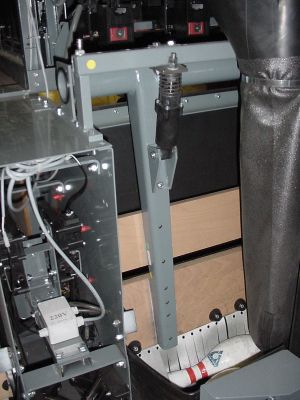
new cushion shock bracket is bolted to the cushion frame. Refer to Figure 1.
NEW STYLE
CUSHION
SHOCK
99-020402-002
NEW STYLE
SHOCK
MOUNTING
BRACKET
NEW STYLE
CUSHION
FRAME
ASSEMBLY
47-025639-009
FIGURE 1
(C) 2004 Brunswick Bowling & Billiards Corporation, 525 West Laketon Avenue, P.O. Box 329, Muskegon, Michigan 49443-0329 Page 1 of 2
8 Bowling Center Operating Procedures ManualSample Service Bulletin - Page 2
The new style of heavy duty ball cushion frame went into production pinsetters starting with series 512 machines.
The part number for the new heavy duty ball cushion frame, which includes the shock mounting bracket, is 47-
025639-009.
Note: When ordering this new ball cushion frame assembly, you must make sure that the cushion shock you
are using is the new style shock, refer to Figure 1, without the shock fluid reservoir. The older type shock
will not fit into the new cushion frame shock bracket. Part number of the new shock is 99-020402-002.
This new ball cushion frame assembly is usable in all models of GS-Series pinsetters.
If you have any questions about this Service Bulletin, call the Customer Support Line at 1-800-323-8141 (USA).
For assistance in international bowling centers, contact your local Brunswick area office.
Glenn Josey David E. Rice
Worldwide Installation Training/Audit Manager Director of Worldwide Service
Page 2 of 2
Bowling Center Operating Procedures Manual 9Pinsetters
GS SERIES PREVENTIVE MAINTENANCE PROGRAM
All chief mechanics and their mechanical staff should be responsible for the inspection and completion of
the Pinsetter Preventive Maintenance Program. Each Pinsetter should be inspected every 6 months, this
inspection program does not take the place of normal inspection, adjustments and troubleshooting of the
Pinsetter, but is an added, intensive program.
1. The chief mechanic and his mechanical staff, on a regular schedule, will inspect each Pinsetter
following the instructions set forth in this procedure.
2. Each center is required to have a 2 or 3-ring notebook binder. The binder will consist of one
GS Pinsetter Preventive Maintenance Work Schedule, one GS Parts Pending Items, and one
GS Parts Usage Log) for each Pinsetter. The outside of the 2 or 3-ring binder will be marked as
GS Pinsetter Maintenance program for identification purposes.
3. The GS Pinsetter Maintenance program binder will also include one copy of the preventive
maintenance work schedule instruction.
4. Check off the appropriate box with an “X” when that portion of the Pinsetter has been in-
spected, adjusted or corrected per the preventive maintenance work schedule.
5. If pending or part replacement is needed, and an inspection has been completed, then mark the
box with a half of an “X”, after replacement and adjustment of the pending item(s) are com-
pleted, finish marking the box.
6. All parts that are used to complete the GS Pinsetter Maintenance program inspection must be
written on the parts usage form for future ordering.
7. All parts that are needed to complete the GS Pinsetter inspection must be written on the parts
pending form.
10 Bowling Center Operating Procedures ManualInstructions for GS Pinsetters Preventive Maintenance Work Schedule
Elevator Assembly
1. Inspect condition of the frames welds. Check for loose or missing hardware inspect all metal
for stress cracks.
2. Inspect all shafts, bearings, sprockets, chains and pulleys for condition and adjustment. Check
all pin shovels and shovel hardware. Inspect all shovel pivot levers, inspect centering guide
condition and tighten all hardware.
3. Inspect condition and mounting of guards and verify guard identification labels are in place.
4. (Series 42 and below) Inspect condition, location and adjustment of rubber knockout cords
and pin ejecting flap.
5. (Series 42 and below) Inspect condition, adjustment and hardware on the pin turn wires.
6. (Series 12 and below) Inspect welds, hardware and adjustments of single feed pin chute
assembly. (Series 13 through 42) Check the adjustment, mounting hardware and welds and
condition of the dual feed pin chute. Inspect the “Y” switch, flipper stoppers, deflector shoes
and rubber cords for proper adjustment and condition.
7. Inspect the mounting and adjustment of the elevator control switch. Check the mounting and
function of the mechanic’s rear control box and trouble light. Verify that all elevator cables are
intact, routed correctly and secured.
8. (Series 43 and above) Inspect the mounting hardware, condition and adjustments of the shark
assembly and pin guide wedges. Check the shovel cam for adjustment and condition. Check the
alignment and mesh of the drive and drive spur gears. Inspect the condition and operation of the
fin switch. Inspect the tensioning and condition of the transfer belts. Inspect the mounting
hardware and condition of the deflector shoe. Inspect the spring for the fin switch.
9. (Smart shark) Inspect the condition, alignment, adjustment and operation of the pin count
switch. Check that all switch and switch mounting bracket hardware is tight. Check for correct
cable routing.
10. (Smart Shark) Check the smart shark solenoid and solenoid linkage. Check for proper opera-
tion of the smart shark. Check all mounting hardware and fasteners.
Transport Assembly
11. Inspect the condition of the welds and feet on the long pit transport frame. Inspect the condition
of the welds and mounting hardware on the short pit side frames.
12. Inspect the mounting hardware and condition of the transport band boards. Check the condi-
tion and tracking of the transport band carpet. Inspect the front and rear rollers for bearing and
shaft condition, correct tensioning and alignment in mounting slots. Inspect the condition and
operation of the centering guide rollers. Tighten end caps on the front roller and oil bearing.
Inspect the bearing blocks on the rear roller and oil bearings.
Bowling Center Operating Procedures Manual 1113. Inspect the condition and tensioning of the transport band drive belts. Inspect the mounting
hardware on the idler and tensioner assemblies. Check the condition of the idler pulleys.
14. Inspect the condition and mounting hardware on the pin feed deflectors and mounting brackets.
Check the adjustment on the pin feed deflectors and tighten the hardware.
Ball Cushion and Pit Curtain
15. Inspect the condition and mounting hardware on the ball cushion board and the impact strips.
Check the attachment of the rubber cushion to the board and the facing to the rubber cushion.
Inspect the cushion frame welds, and check the mounting hardware. Inspect the nylon cushion
bearings for wear and check the location and hardware on the stop collars. Inspect the cushion
assembly for proper adjustment and stress cracks.
16. Inspect the mounting, adjustment and fluid level in the ball cushion shock absorber. Inspect the
mounting and location of the shock absorber.
17. Inspect the mounting and rubber overflow pad on the single feed overflow chute. Inspect the
condition and mounting of the dual feed overflow chute. Inspect the condition of the chute felt
and check the bond to the metal on units so equipped. Check the condition of the pin wipers.
Inspect the condition and adjustment of the overflow socks. Check chutes for metal or plastic
stress cracks. Check all plastic overflow chute mounting bumpers and mounting brackets.
18. Inspect the condition of the pit curtain and check the mounting hardware.
Ball Accelerator Assembly
19. Inspect the condition of the frame welds. Check that foot guards are in place. Inspect the
condition and location of the ladder.
20. Inspect the condition and mounting hardware on the ball door protector plates. Inspect condi-
tion and mounting hardware on the ball door wedges. Inspect the condition and mounting
hardware on the kickback phenolic plates.
21. Inspect the accelerator motor and motor bearings for smooth operation. Check the motor
power cord. Inspect the alignment of the motor. Check for excessive noise or vibration.
22. Inspect the condition of the flat belt. Inspect the flat belt guard for proper adjustment. Inspect
the driving drum condition and check for smooth operation. Verify that all driving drum hard-
ware is in place. Driving drums should be pulled out and bearings oiled. Inspect accelerator
tracks for worn covers.
23. Inspect the ball door locking mechanism for proper adjustment. Check the condition of the ball
door, all door button and door locking bolt. Inspect the ball door solenoid for correct operation
and check the routing of the solenoid cable. Verify that ball door shafts and collars rotate freely.
12 Bowling Center Operating Procedures ManualSweep Wagon Assembly
24. Inspect the condition of the sweep wagon frame and frame welds. Check the roller mounting
and adjustment. Inspect the condition of the leaf springs if so equipped. Check the condition of
the pusher rods and pusher rod bushings. Inspect the conditions of the protector blocks and
block mounting hardware. Check all sweep wagon hardware.
25. Inspect the condition of the sweep board and adapters. Check the adjustment of the sweep
board and adapters.
26. Inspect the condition of all sweep release mechanism components. Check all sweep release
mounting hardware. Inspect for missing springs or worn linkage and pivot bushings. Check the
condition of the chain and clevis. Check the operation of the solenoid. Inspect the solenoid
cable routing. The cable should be secured on both sides of the solenoid plug.
27. Inspect the sweep attenuator and sweep shock absorber for loose or missing hardware. Check
the sweep shock absorber fluid level. Check the attenuator and G-Switch cable for proper
adjustment. Inspect all pivot points for wear. Inspect the G-Switch cable routing.
Setting Table Assembly
28. Inspect the setting table frame for wear or broken welds. Check for loose or missing hardware.
Check the vertical swing shaft stop bolts for proper adjustment. Inspect the condition of the
vertical helper springs (for units so equipped). Check the metal around swing shaft supports for
stress cracks.
29. Check for loose or missing spotting tong and geared rack hardware. Inspect the S.T. Switch
mounting and check the adjustment. Inspect the condition of the tongs, gears, and toothed
racks. Check the operation of the tongs. Inspect the tong dampers for wear and tighten spotting
tong hardware.
30. Inspect all cable channels and conduits for wear. Check that all Channels and conduits are
secured to the frame. Inspect the condition of the table harness plug and its mounting bracket
and hardware.
31. Inspect all welds on the swing shafts and connection rods. Check for loose or missing connect-
ing rod hardware. Check the adjustment of the stop collars. Inspect the swing shaft bearings for
wear. Inspect the condition of the table spring. Inspect the condition and mounting of the table
jam roller. Check the adjustment of the horizontal stop bolt. Verify that all pin holders are
secured to the square shafts. For older round shaft pinholder mounting, check the ground
screws.
32. Inspect the TS-1 Jam Switch mounting and adjustment. Check the actuator arm and cam for
free operation. Check for loose or missing hardware and springs. Inspect the TS-2 jam switch
mounting and adjustment.
Bowling Center Operating Procedures Manual 1333. Inspect all pin holders and pin holder solenoids for correct mounting. Check the switch fingers
for correct pivoting. Inspect all pin holder switches for tight mounting. Check all pin holder
connectors and wiring for routing and connection. Inspect the adjustment on the pin detector
plates. Check the adjustment on the switch actuator springs in units so equipped.
34. Inspect the mounting of the table racks to the table. Check the adjustment and condition of the
small and large roller support assemblies on tower up pinsetters. Inspect the condition of the
toothed racks and or chain drives. Check the condition of the T-Stop. Check the mounting of
the O.O.R. Actuator cam. Inspect the condition of the chain, clevis, pivot bearing, and master
chain link.
Drive Frame Assembly
35. Inspect the welds and condition of the sweep shaft. Check the sweep shaft supports for secure
mounting. Inspect the sweep shaft bearings for signs of wear. Inspect the connecting rods and
verify all hardware is in place and secure.
36. Inspect the condition and welds on the L.H. and R.H. drive assemblies. Check for loose or
missing hardware. Inspect all cable channels and cables for condition and routing. Check for
any worn shaft bearings. Check the chain tensioners for condition and adjustment. Inspect the
frame counter for correct operation.
37. Inspect the spotting tong drive for loose or missing hardware. Check for loose or worn gears.
Check the spotting tong solenoids for proper operation. Check the spotting tong clutch for
correct operation and check the condition of the clutch shaft. Inspect the mesh between the
square shaft drive and the spur gear. Check the condition of the square shaft drive gear.
38. Inspect the motors for correct mounting and alignment. Check the condition of all V-Belts.
Inspect the motor cables for correct routing. Check the condition of the motor tensioning
springs. Check all motor mounting plate bushings. Check for excessive Vibration in the motor
and belt operation. Wipe all motor belts down by removing the belts. Wrap a rag around the
belts and clean thoroughly. Blow dust out of the motor fan covers as needed.
39. Inspect the stroke limiter for a bent or cracked plate and loose or missing hardware. Check the
mounting and fluid level in the stroke limiter shock absorber. Check the condition of the rubber
bumper. Check the solenoid for proper operation. Inspect the square shaft, the linkage and the
square shaft latch for correct adjustment. Be sure the stroke limiter plate is not rubbing on the
tower rack.
40. Inspect the condition of the double V-Belts. Check for loose or missing tensioner mounting
hardware. Check the tensioner shaft and bearings for loose or noisy operation and clean belts.
Remove the tensioner assembly from the machine. Clean and oil the bearings.
41. Inspect the condition of the setting table and sweep motor drive assemblies. Check for worn or
damaged chains. Inspect the pinion shafts and gears for adjustment and condition. Check for
loose or missing bearing plate hardware. Inspect the condition of bearing plate bearings and
drive sprocket shafts. Inspect the master links on the chains.
14 Bowling Center Operating Procedures Manual42. Inspect the condition of the guide tower assembly. Check the mounting and adjustment on the
TS- 2 and O.O.R. Switch. Check for correct switch and cable mounting. Check for loose or
missing guide tower hardware. Inspect the condition of the lift chain sprocket. Check the
condition of the table jam lever and spring.
43. Inspect the sweep and table drive shaft assemblies. Check for shaft wear. Check for chain
wear and proper tensioning. Inspect the crank arms and verify they are secure on the shafts.
Check the sprockets for wear. Inspect the pinion shaft assembly on pinsetters so equipped.
Check the shaft and bearings for wear. Inspect pinion gears for wear on pinsetters so equipped.
Check the adjustment of the pinion gears to the tower racks on pinsetters so equipped. Inspect
pinion gears for cracks.
44. Inspect the switch cluster. Check the switch cluster housing to make sure it is secure. Check the
adjustment on the A, B, C, and D Switch. Check the adjustment on the switch cam. Check all
scorer switches on pinsetters so equipped.
Main Frame Assembly
45. Inspect the main frame. Check for wear points or broken welds. Check for loose or missing
hardware. Check the main support braces and verify they are secure.
46. Inspect the pinlight fixture. Check and verify that the fixture is securely mounted. Check the
lamps and lamp sockets. Check the power cord routing.
47. Inspect the guards. Check for wear points or broken welds. Check for loose or missing
hardware. Check for any missing guards. Check the work platform and the work platform
braces and hardware.
48. Inspect the electrical box mounting. Check and verify that the mounting plate and rubber
bumpers are secure. Check and verify that all electrical box mounting receptacles and hardware
are in place and secure. Make sure the grounding straps are connected.
Distributor Assembly
49. Inspect the distributor frame assembly. Check for worn or damaged frame components and
welds. Check for loose or missing hardware. Check and verify that the dust pan is secure.
Check the distributor rails and extensions for wear or cracks. Check the distributor stations for
wear or cracks. Inspect the lower pin guides for bent or missing parts. Check the corner turn
rails and corner pin turn devices for loose or missing hardware and for correct adjustment.
50. Inspect the distributor shafts, pulleys and belting. Check for worn or damaged shafts or bear-
ings. Check for worn or cracked pulleys. Inspect the condition of the distributor belting. Check
the condition of distributor gears and verify proper gear mesh. Check the alignment of all shafts,
pulleys and belting. Check for any missing shaft, bearing or pulley hardware.
51. On series 12 and below, inspect the pin separators and pin centering devices. Check the
condition, mounting and adjustment on the pin separators. Check the condition, mounting and
adjustment on the pin centering devices.
Bowling Center Operating Procedures Manual 1552. Inspect the distributor pin stations. Verify all pin stops are in place. Check the pin sliders for
free operation. Check the pin slider for cracks or breaks. Check for loose or missing pin station
hardware. Check the ejector flaps for wear or cracking. Check the retaining bows for wear or
cracking. Check for worn, cracked or misadjusted pin release levers. Verify that all pin station
springs are in place. Inspect the top and bottom housing for cracks or wear.
Electrical
53. Inspect the electrical boxes and box mounting hardware. Check the ground straps and verify
that they are in place and secure. Verify that all cables are routed correctly. Inspect all box
covers to verify they are in place and secure. Check the pin light bypass switch for operation on
units so equipped. Are all box switch guards in place? Check all cables and box connectors for
correct seating. Check the 5-VOLT power supply adjustment on silver box, universal silver
box, and consolidated electronics.
54. Inspect the ball detector and reflector. Check and verify all mounting hardware is secure.
Check the ball detector assembly for proper adjustment.
55. On stand-alone units, inspect the player control station. Verify that the player control station is
mounted securely, the cable is routed correctly and that the unit is operating properly.
56. Inspect the ball rack reset button. Check for correct operation and check the cable routing and
connection.
57. On units so equipped, inspect the manager’s control box. Check on/off switches for proper
operation. Are both indicator lamps working? Verify that both frame counters work.
Power Ball Lift - Even Lane
58. Check the condition and mounting of the ball lift tires. Check the condition of the lift tire shafts
and bearings. Check the condition and operation of the ball lift clutch.
59. Check the ball lift motor for correct operation and mounting. Check the motor pulley for proper
alignment. Check the drive belt condition and alignment. Check the top idler pulley.
60. Check the ball lift tracks for correct mounting. Check the condition of the lift rubber track and
leather tracks and verify that they are secure. Check for loose or worn rubber and leather
tracks.
Administration And Organization
61. Is a spare parts and inventory control system in place? Are adequate parts on hand and are
these parts on inventory and accessible? Are all spare motors labeled for status? Are all spare
electronics boards labeled for status?
62. Verify that the correct hand tools are in place. Are the hand tools organized for ready access?
63. Verify that the correct cleaning and lubrication products and supplier are on hand. Check and
verify the supplies are adequate and that the correct approved materials are in use.
16 Bowling Center Operating Procedures Manual64. Verify that you have current product operation manuals and product service part manuals. Are
Service Bulletins in the center?
65. Verify that the center is using Preventive Maintenance forms and these forms have been appro-
priately checked and that the parts pending and parts usage reports are up to date.
Cleaning And Lubrication
66. Verify that the Preventive Maintenance Pinsetter Cleaning schedule is being used and that all
technicians and mechanics responsible are properly cleaning the pinsetters and recording this
work on the schedule.
67. Check the GS Pinsetter Operation and Service Manual for proper lubrication and maintenance
schedules. Please refer to Section 7, starting at Page 7-3 in the GS Series Pinsetter Operations
and Service Manual. Do not over lubricate any areas of the automatic pinsetter.
68. Verify that safety training has taken place with all technical personnel working on the pinsetters
and other bowling equipment.
Bowling Center Operating Procedures Manual 17GS SERIES PINSETTERS PREVENTIVE MAINTENANCE WORK SCHEDULE
INSPECT – CORRECT – CLEAN – LUBRICATE
ELEVATOR ASSEMBLY ADJUST 1 2 3 4 5 6 7 8
1 FRAME AND WELDED ASSEMBLIES
2 DRIVE TRAIN AND SHOVELS
3 PINSETTER GUARDS
4 RUBBER CORDS AND EJECTING FLAPS
5 PIN TURN WIRES
6 PIN CHUTE ASSEMBLY FOR SINGLE AND DUAL FEED
7 ELEVATOR ELECTRICAL COMPONENTS
8 SHARK SWITCH AND PIN TURN ASSEMBLIES
9 PIN COUNT SWITCH (SMART SHARK)
10 SMART SHARK SOLENOID AND LINKAGE
TRANSPORT BAND ASSEMBLY
11 MAIN FRAME, FEET AND SIDE FRAMES
12 TRANSPORT BAND BOARD, CARPET AND ROLLERS
13 TRANSPORT BAND DRIVE BELTS AND PULLEYS
14 PIN FEED DEFLECTORS
BALL CUSHION AND PIT CURTAIN
15 CUSHION BOARD, FRAME, FACING AND BEARINGS
16 SHOCK ABSORBERS AND PULLEYS
17 SINGLE AND DUAL FEED OVERFLOW CHUTES
18 PIT CURTAIN
BALL ACCELERATOR ASSEMBLY
19 FRAME AND WELDED ASSEMBLIES
20 BALL DOOR PROTECTOR, FIBER PLATES, RINGS
21 MOTORS AND DRIVE BELT
22 FLAT BELT AND DRIVING DRUM
23 BALL DOOR AND LOCKING ASSEMBLIES
SWEEP WAGON ASSEMBLY
24 SWEEP WAGON FRAME
25 SWEEP BOARD AND ADAPTERS
26 SWEEP RELEASE MECHANISM
27 SWEEP ATTENUATOR AND HYDRAULIC
SETTING TABLE ASSEMBLY
28 FRAME AND WELDED ASSEMBLIES
29 SPOTTING TONGS AND GEARED RACKS
30 TABLE HARNESS AND CABLE CHANNELS
31 SWING SHAFTS AND CONNECTING RODS
32 TABLE JAM SWITCH
33 PIN HOLDERS AND PIN SWITCHES
34 SETTING TABLE ROLLERS AND ROLLER SUPPORTS
DRIVE FRAME ASSEMBLY
35 SWEEP SHAFT AND DRIVE
36 RIGHT AND LEFT DRIVE FRAME ASSEMBLY
37 SPOTTING TONG DRIVE ASSEMBLY
38 MOTORS, BELTS AND MOTOR MOUNTINGS
39 STROKE LIMITER ASSEMBLY
40 FRONT PULLEY AND V BELT TENSIONER
41 SETTING TABLE AND SWEEP MOTOR DRIVES
42 GUIDE TOWER ASSEMBLY
43 SWEEP, TABLE AND DRIVE SHAFT ASSEMBLIES
44 SWITCH CLUSTER AND SCORER SWITCHS
18 Bowling Center Operating Procedures ManualADJUST 1 2 3 4 5 6 7 8
MAIN FRAME ASSEMBLY
45 SWITCH CLUSTER / SWITCHES
46 PINLIGHT FIXTURE
47 GUARDS AND WORK PLATFORM
48 ELECTRICAL BOXES AND MOUNTING HARDWARE
DISTRIBUTOR ASSEMBLY
49 FRAME AND WELDED ASSEMBLIES
50 SHAFTS, PULLEYS AND BELTING
51 PIN TURN, PIN CENTERING DEVICES
52 PIN STATIONS AND SLIDERS
ELECTRICAL COMPONENTS
53 BOXES AND MOUNTING HARDWARE
54 BALL DETECTOR AND REFLECTORS
55 PLAYER CONTROL STATION IF SO EQUIPPED
56 BALL RACK RESET BUTTON
57 MANGERS CONTROL BOX
POWER BALL LIFT (EVEN LANES)
58 BALL LIFT TIRES
59 MOTOR AND DRIVE BELTS
60 BALL LIFT TRACKS / RUBBERS / LEATHERS
ADMINISTRATION AND ORGANIZATION
61 INVENTORY CONTROL
62 HAND AND POWER TOOLS
63 CLEANING AND LUBRICATION SUPPLIES
64 OPERATING MANUALS
65 PARTS PENDING AND PARTS USAGE
CLEANING AND LUBRICATION
66 PINSETTER CLEANING SCHEDULE
67 PINSETTER LUBRICATION SCHEDULE
68 PINSETTER SAFETY TRAINING
DATE PERFORMED
Bowling Center Operating Procedures Manual 19Pinsetter Pending Items - GS Series Pinsetters
Repair - Adjust - Lubricate
Pinsetter Pending Work Item Date Inspected Date Completed Mechanics Name
Center name: _____________________________ Pinsetter number: _________
20 Bowling Center Operating Procedures ManualGS Series Pinsetters
Pinsetter Parts Useage Log
Pinsetter Part Number Part Name Mechanic's Name
Center name: _______________________________________ Pinsetter number: _________
Bowling Center Operating Procedures Manual 21GS PINSETTERS DAILY STOP RECORDS
All chief mechanics and their mechanical staff will be responsible for the timely recording of all pinsetter
malfunctions on the GS Series pinsetter daily stop records.
1. Each facility should have one daily stop record sheet for each pinsetter. This sheet will be kept
on a clipboard located on the back of each pinsetter and every month a new stop sheet will be
posted with a new date.
2. The chief mechanic and mechanical staff upon the correction of any pinsetter malfunction, will
record the lane number, the frame count (off the frame counter on the pinsetter), the error code
of the problem, the corrective action taken to prevent this stop again and the initials of the
mechanic who cleared and repaired the stop. A list of GS Series error codes must be used to
correctly identify the problem.
3. At the beginning of each day, the chief mechanic will be responsible for transferring the previous
daily stops onto the weekly frames per stop records.
4. The GS Series pinsetter daily stop records should be used as a tool for preventive maintenance
programs. It becomes apparent when reoccurring problems exist on particular pinsetters.
5. We suggest that all daily completed stop records should be kept on file for a period of one
year.
22 Bowling Center Operating Procedures ManualGS-Series Stop Sheet Machine No. ________________ Date Frame Count Error Code Corrective Action Mech. Initials Bowling Center Operating Procedures Manual 23
GS Series Pinsetter Error Codes

Std. Code Extend Code*                                         Std. Code Extend Code*
  l—l           **       Power Up in Progress                     60       A Found      Switch A is Not Expected But Found
     -ll-       **       No Errors                                61       B Found      Switch B is Not Expected But Found
 None                    The Lane Initialized                     62       C Found      Switch C is Not Expected But Found
     A0         **       PCS Not Communicating                    63       D Found      Switch D is Not Expected But Found
     A1         **       PCS Not Sending Correct Response         64      SM Found      Switch SM is Not Expected But Found
     F0         **       External RAM Testing Failure             65       G Found      Switch G is Not Expected But Found
     F1         **       Prom Check Sum Failure                   66       ST Found     Switch ST is Not Expected But Found
     80         **       Battery Back-up RAM Failure              67      OOR Found Switch OOR is Not Expected But Found
     P0      Pin OOR     Out-of-Range                             70       A Ntfnd      Switch A Expected But Not Found
     01      Pin 1 Ld    Pin Loading Time Out Pin 1               71       B Ntfnd      Switch B Expected But Not Found
     02      Pin 2 Ld    Pin Loading Time Out Pin 2               72       C Ntfnd      Switch C Expected But Not Found
     03      Pin 3 Ld    Pin Loading Time Out Pin 3               73       D Ntfnd      Switch D Expected But Not Found
     04      Pin 4 Ld    Pin Loading Time Out Pin 4               74       SM Ntfnd     Switch SM Expected But Not Found
     05      Pin 5 Ld    Pin Loading Time Out Pin 5               75       G Ntfnd      Switch G Expected But Not Found
     06      Pin 6 Ld    Pin Loading Time Out Pin 6               76       ST Ntfnd     Switch ST Expected But Not Found
     07      Pin 7 Ld    Pin Loading Time Out Pin 7               90        Invld 0     Invalid Machine State 0
     08      Pin 8 Ld    Pin Loading Time Out Pin 8               91        Invld 1     Invalid Machine State 1
     09      Pin 9 Ld    Pin Loading Time Out Pin 9               92        Invld 2     Invalid Machine State 2
     10      Pin 10 Ld   Pin Loading Time Out Pin 10              93        Invld 3     Invalid Machine State 3
     50      Detect 10   #10 Pin Not Detected in Diagnostics      94        Invld 4     Invalid Machine State 4
     51      Detect 1    #1 Pin Not Detected in Diagnostics       95        Invld 5     Invalid Machine State 5
     52      Detect 2    #2 Pin Not Detected in Diagnostics       EJ       Elev Jam     Elevator Jam
     53      Detect 3    #3 Pin Not Detected in Diagnostics      EL         Pin Cnt     Pin Count Switch Shorted for 5 seconds
     54      Detect 4    #4 Pin Not Detected in Diagnostics       J1       TS1 Jam      Jam Switch TS1
     55      Detect 5    #5 Pin Not Detected in Diagnostics       J2       TS2 Jam      Jam Switch TS2 (Tower)
     56      Detect 6    #6 Pin Not Detected in Diagnostics       *          BA         Accelerator Motor (overload)
     57      Detect 7    #7 Pin Not Detected in Diagnostics    CPU Lost    CPU Lost     Nexgen CPU Malfuncton
     58      Detect 8    #8 Pin Not Detected in Diagnostics
     59      Detect 9    #9 Pin Not Detected in Diagnostics

            NOTE: NextGen Electronics displays either Standard Code or Extended Code
            where as Consolidated displays Standard Code.

            * = Nexgen Electronics only

            ** = Consolidated Electronics only

24                                                                    Bowling Center Operating Procedures Manual
GS SERIES PINSETTER WEEKLY FRAMES PER STOP RECORDS
All chief mechanics will be responsible for the timely recording of all games or frames and the recap of all
daily stops, from the GS Series daily stop records.
1. At the beginning of each month, a new Weekly Frames per Stop record sheet will be used.
Include the day, and date for reference.
2. Each facility will have one Weekly Frames per Stop sheet for all pinsetters. The form that is in
use will be kept posted on a clipboard located in the mechanics’ shop.
3. At the beginning of each day, the chief mechanic will be responsible for transferring the previous
daily stops onto the weekly frames per stop sheet and obtaining the number of games bowled or
total frames. The frames or games number will be obtained from the manager’s console, or
command network system, or pinsetter meter readings. Pinsetter meter readings require a daily
meter reading, and if done, should only be done on a weekly basis.
4. Each style of stops should be recorded, out of range (oor), respots (rs), ball returns (br) and
others.
5. Total each day the number of stops.
6. If you are using total number of games for record keeping from management, you will need to
convert these games to frames. Multiply the number of games times 11. This is your total
frames.
7. Divide the number of frames by the number of stops. This is your frames per stop (fps).
8. At the end of each week and month, recap and cross check all frames per stop and pinsetter
stops.
9. The GS Series Weekly Frames per Stop records should be used as a tool for preventive
maintenance programs. The goal is to have the highest pinsetter frames per stops.
10. We suggest that you keep all weekly frames per stop records on file for a period of 2 years.
Bowling Center Operating Procedures Manual 25GS-Series Pinsetter Weekly Stop Report
Center Name ____________________________________________________ Week Ending __________________
Daily Frame Totals
Daily Stop Totals
Error Code Description Monday Tuesday Wednesday Thursday Friday Saturday Sunday Total
1 Pin 1 – Time Out of Jam
2 Pin 2 – Time Out of Jam
3 Pin 3 – Time Out of Jam
4 Pin 4 – Time Out of Jam
5 Pin 5 – Time Out of Jam
6 Pin 6 – Time Out of Jam
7 Pin 7 – Time Out of Jam
8 Pin 8 – Time Out of Jam
9 Pin 9 – Time Out of Jam
10 Pin 10 – Time Out of Jam
*11 Pin Jam – Left-Hand Corner
*12 Pin Jam – Right-Hand Corner
*13 Pin Jam – Left Distributor Lane 1
*14 Pin Jam – Left Center Distrib. Lane 2
*15 Pin Jam – Right Center Distrib. Lane 3
*16 Pin Jam – Right Distributor Lane 4
*17 Pin Jam – Shark Switch
*18 Pin Jam – Pin Guide Wedges
*19 Pin Jam – Pin Head First
*20 Pin Stuck In Elevator
*21 Pin Under Pin Feed Deflector
*22 Pin in Ball Accelerator
*23 Ball Stuck in Pit
*24 Ball Stuck In Ball Lift
*25 Pin Blocking Ball Door
*26 Pin Jammed in Setting Table
*27 Spotting Tongs Jammed
*28 Sweep Roller Not in Slot
*29 Belt Broken
*30 Belt Loose
*31 Overflow Chute/Sock Jam #7 Pin Side
*32 Overflow Chute/Sock Jam #10 Pin
*50 Pin Holder Switch Malfunction
60 Switch A Not Expected but Found
61 Switch B Not Expected but Found
62 Switch C Not Expected but Found
63 Switch D Not Expected but Found
64 Switch SM Not Expected but Found
65 Switch G Not Expected but Found
66 Switch ST Not Expected but Found
67 Switch OOR Not Expected but Found
70 Switch A Expected but Not Found
71 Switch B Expected but Not Found
72 Switch C Expected but Not Found
73 Switch D Expected but Not Found
74 Switch SM Expected but Not Found
75 Switch G Expected but Not Found
76 Switch ST Expected but Not Found
90 Invalid Machine State 0
91 Invalid Machine State 1
92 Invalid Machine State 2
93 Invalid Machine State 3
94 Invalid Machine State 4
95 Invalid Machine State 5
98 Electronic Box Failure
99 Part Broken/Other (Explain on Back)
EJ Elevator Jam
EL Pin Count Switch Failure
J1 Jam Switch TS1
J2 Jam Switch TS2 (Tower)
PO Out-of-Range
* These code numbers are not displayed by the Pinsetter CPU LED display. Explain problems or irregularities on the back of this report
26 Bowling Center Operating Procedures ManualGS SERIES PINSETTER MONTHLY FRAMES PER STOP RECORDS
All chief mechanics will be responsible for the timely recording of the FPS from the Pinsetter Weekly
Frames Per Stop Records. This form will be used for GS Series Pinsetters.
1. At the beginning of each month, the chief mechanic should total the fps from the pinsetter
weekly frames per stop records.
2. Record the total fps from the universal pinsetter monthly frames per stop records sheet.
3. Compare previous months of fps to determine if the pinsetters are operating better or worse.
4. Try to determine the best approach for obtaining consistent monthly frames per stop on the
pinsetters.
5. All universal pinsetter monthly frames per stop records will be kept until the form expires. The
expired form should be filed in the mechanics’ shop for record keeping.
6. The current form should be kept on a clipboard in the mechanics’ shop.
Bowling Center Operating Procedures Manual 27UNIVERSAL MONTHLY FRAMES PER STOP RECORD
2004 2005 2006 2007 2008 2009
JANUARY
FEBRUARY
MARCH
APRIL
MAY
JUNE
JULY
AUGUST
SEPTEMBER
OCTOBER
NOVEMBER
DECEMBER
2010 2011 2012 2013 2014 2015
JANUARY
FEBRUARY
MARCH
APRIL
MAY
JUNE
JULY
AUGUST
SEPTEMBER
OCTOBER
NOVEMBER
DECEMBER
28 Bowling Center Operating Procedures ManualCONTROL COUNTER MALFUNCTION REPORT
All counter control and management personnel, while on duty at the control counter, are responsible for
recording Pinsetter and equipment malfunctions on the Control Counter Malfunction Report sheet.
1. At the start of each day, the control counter malfunction report should be dated and signed in
the appropriate areas on the form. During any shift change, the new counter control personnel
should also sign the form.
2. As Pinsetter and equipment malfunctions occur, either reported or observed by the counter
control personnel, the malfunction should immediately be recorded on the Control Counter
Malfunction Report sheet.
3. The control counter malfunction report is not limited to the recording of just the problems listed
on the form. Any problems concerning safety, lighting, heating, air conditioning, bowling equip-
ment or anything our customers or employees report as a problem, should be noted in the
comments section.
4. It is the responsibility of the chief mechanic, on a daily basis, to check this report. This will
allow the mechanics to have the input of customers and employees. Cross checking of mainte-
nance information is a vital source of preventive maintenance.
5. The counter control malfunction report should be kept on a clipboard at the control counter and
old reports kept on file in the manager’s office for a period of 1 year.
Bowling Center Operating Procedures Manual 29Control Counter Malfunction Report
Lane Number 1 2 3 4 5 6 7 8 9 10 11 12 13 14 15 16 17 18 19 20
Ball Return
Blackout
Pin Respot
Failed to Cycle
Out of Range
Foul Light
Multiple Cycles
Ball Hit Sweep
P.C.S. Lights
Scorer Console
Scorer Overhead
Score Correction
Scorer Lockup
______________________________________________________________________
______________________________________________________________________
______________________________________________________________________
Comments ______________________________________________________________________
Lane Number 21 22 23 24 25 26 27 28 29 30 31 32 33 34 35 36 37 38 39 40
Ball Return
Blackout
Pin Respot
Failed to Cycle
Out of Range
Foul Light
Multiple Cycles
Ball Hit Sweep
P.C.S. Lights
Scorer Console
Scorer Overhead
Score Correction
Scorer Lockup
______________________________________________________________________
______________________________________________________________________
______________________________________________________________________
Comments ______________________________________________________________________
DATE: ____________ SIGNATURE: _____________________________
30 Bowling Center Operating Procedures ManualAutomatic Scorers
AUTOMATIC SCORER PREVENTIVE MAINTENANCE SCHEDULE
All chief mechanics will be responsible for completion and documentation of the items listed on the
Automatic Scorer Preventive Maintenance Work Schedule.
1. The chief mechanic and mechanical staff on a daily, weekly and monthly routine will complete
all the work assignments listed on the Automatic Scorer Preventive Maintenance Schedule.
2. For daily service, check off the appropriate box with an “X” n the schedule when the work is
completed in each area. The Automatic Scorer Preventive Maintenance Schedule contains
maintenance instructions that cover all current versions of Brunswick scorers.
3. For monthly services, place the mechanics’ initial n the shaded box that pertains to the work
needed. Again, the Automatic Scorer Preventive Maintenance Schedule contains maintenance
for all scorers.
4. If pending work or parts replacement exists, do not check off that area of the work schedule
until all work has been completed.
5. The work schedules that are in use should be posted on a clipboard in the mechanics’ shop
area. All completed forms should be kept on file in the mechanics’ shop for a period of 2 years.
Bowling Center Operating Procedures Manual 3132
AUTOMATIC SCORER PREVENTIVE MAINTENANCE SCHEDULE
DAY OF THE MONTH MONTH: ____________ 1 2 3 4 5 6 7 8 9 10 11 12 13 14 15 16 17 18 19 20 21 22 23 24 25 26 27 28 29 30 31
Check Error Log
Check Console Keypad
Check Managers Keypad
Check Activity Report
Check Foul Unit Operation
Check Ball Detects
MONTH FOR SERVICE Jan. Feb. Mar. Apr. May June July Aug. Sept. Oct. Nov. Dec.
Clean Lower Console Monitors
Clean Upper Overhead Monitors
Clean Lower Console, L.G.P. or Scoring Computer
Circuit Board Connectors
Clean Scorer Keypads and Consoles
Clean Ball Detects and Reflectors
Check Service Light Operation
Check Intercom Operation
Check Auto Foul Signal Function
Check Console/ Keypad Condition / Mounting
Inspect Cables and Connectors
Adjust Overhead Monitors
Adjust Lower Console Monitors
Verify Scoring is Correct
Check Console Power Supply
Check Incoming L.G.P. / Scoring Computer /
Power Voltage
Check L.G.P. / Console / Keypad / Scoring
Computer Mounting
Check 1st and 2nd Ball Light Operation
Check Table Switches on GS Series Pinsetters
Run GS Pinsetters in Machine Diagnostics
Check all Diagnostic Indicator LED's
Check Pinsetter to Scorer Cable Routing
Bowling Center Operating Procedures ManualLanes
LANE PREVENTIVE MAINTENANCE SCHEDULE
All chief mechanics will be responsible for the verification and compliance to this maintenance schedule by
the Lane Maintenance Staff.
1. Enter the month the Lane Preventive Maintenance Schedule starts.
2. A designated person(s) will be assigned to complete the items listed on the Lane Maintenance
Schedule. This person is typically called the Lane Person.
3. Upon completion of each task, the Lane Person will place an “X” in the appropriate shaded
block.
4. The form that is in use will be kept posted on a clipboard in the mechanics’ shop. All completed
forms should be kept on file in the mechanics’ shop for a period of 1 year.
Bowling Center Operating Procedures Manual 33General Lane Maintenance Schedule
There are many items related to lanes that require routing scheduled maintenance. To serve as a reminder of the
maintenance that must be performed, a list of the routine maintenance items and a schedule of lane responsibilities
follow.
Daily Maintenance
1. Dust caps and gutters
2. Dust lanes
3. Dust approaches
4. Dust ball hood and rack
5. Clean lane and pin deck
6. Condition lanes
7. Clean lane machine
8. Spot clean approaches
9. Inspect approaches
10. Wash soiled laundry
11. Clean and polish house balls, as required
12. Clean hoods and racks
Weekly Maintenance
1. Clean bowler seating
2. Buff synthetic approaches
3. Change carpet covers
4. Change pin dusters
5. Change ball wipes
6. Clean bowler seating
(A) 25% of all the equipment to schedule
Monthly Maintenance
1. Dust masking units
2. Clean upper overheads
3. Clean lower consoles
4. Vacuum hand dryers
5. Clean flat gutters
6. Clean kickbacks
7. Vacuum ball lifts
8. Inspect lanes
9. Inspect pit ends, screws plugs, and joints
10. Clean caps and gutter
(A) 25% of all the equipment per week
34 Bowling Center Operating Procedures ManualLANE PREVENTIVE MAINTENANCE SCHEDULE
DAILY, WEEKLY, AND MONTHLY Month ___________________
Day of the Month Code 1 2 3 4 5 6 7 8 9 10 11 12 13 14 15 16 17 18 19 20 21 22 23 24 25 26 27 28 29 30 31
Dust Masking Units AS
Dust Caps and Gutters
Clean Caps and Gutters AS
Dust Lanes
Dust Approaches
Dust Ball Hoods/Racks
Clean Upper Overheads A
Clean Lower Consoles A
Clean lane/Pindecks
Condition lanes
Clean Lane Machine
Spot Clean Approaches
Vacuum Hand Dryers A
Clean Hoods and Racks
Clean Bowler Seating A
Buff Synthetic Approach
Clean Flat Gutters A
Clean Kickbacks A
Change Carpet Covers A
Change Pin Dusters A
Change Ball Wipes A
Vacuum Ball Lifts A
Inspect Approaches
Inspect Lanes
Inspect Pit Ends A
Wash Soiled Laundry
Clean/Polish House Balls AS
KEY CODES: (A) 25% Of All Equipment
(AS) As Needed
Bowling Center Operating Procedures Manual 35Bowling Equipment
Product Trouble Report and Warranty Policy
BRUNSWICK PRODUCT TROUBLE REPORT
All center personnel have the responsibility to reduce cost and product liability. All Brunswick parts carry a
limited warranty period and can be replaced or credited to the center.
1. Enter date of preparation.
2. Enter the original order number from the original invoice or contact your local sales office.
3. Enter the original order date.
4. Enter the contract number, which is obtained from the original invoice or contact your local
sales office.
5. Enter the installation date or the date the product was received. All new products should be
placed into service as soon as possible and dated.
6. Check the box “Replace Discrepant Parts with New”. The only item you should check the box
“issue credit” is when you have already filled the warranty part with another vendor’s part.
7. Enter the region or territory number located on the original invoice.
8. Enter your Brunswick customer number located on your original invoice.
9. Enter your center name and address.
10. Check “hold bags and shoes for Muskegon disposition” for bowling bags and shoes or check
“return parts to Muskegon/Antigo” for all other parts. Do not ship defective parts unless Brun-
swick warranty department advises.
11. Enter the number of failed parts for each item.
12. Enter the complete Brunswick part number for each part.
13. Enter the complete Brunswick part name for each part.
14. Enter the defect code found on the back of the first page of the PTR.
15. Enter the date code of the defective part if it has one.
36 Bowling Center Operating Procedures Manual16. Enter any comments that might help the warranty department in processing the claim or de-
scribe the failure(s).
17. Take pictures of failed warranty items.
18. Sign the product trouble report in the originator box.
19. Forward the product trouble report originals to your local service manager or distributor sales
office for processing and keep the customer copy, packing slip, originator and shipping labels.
20. The local sales office should sign in the other approvals box and follow up with a status report
for each bowling facility.
21. All new PTR’s written must have a different PTR number.
Bowling Center Operating Procedures Manual 37PRODUCT TROUBLE REPORT
PTR NO.
DATE:
Original Order Number ( Check One)
Order Date Issue Credit Memo Against This
Contract Number Replacement Order #
Installation Date Replace Discrepant Parts With New
Region Customer No. (Check One)
Center Hold Bags and Shoes For Muskegon Disp.
Address
Return Parts To Muskegon/ Antigo
City Within 30 Days Or Claim Will Be Denied
Country
State ZIP Int'l Do Not Return Parts Unless Requested
Contact Name/ Phone #
DISCREPANT PARTS
QTY PART NUMBER PART NAME PROBLEM DATE CODE MUSKEGON USE ONLY
535
535
535
535
535
535
535
535
535
535
535
535
535
535
535
535
535
535
535
535
Invoice Amount/Repair charge Exchange Rate US$ 0.00
Freight Charge/ Packing US$ 0.00
Handling Charges US$ 0.00
DM TOTAL 0.00 TOTAL US$ 0.00
COMMENTS
WARRANTY DISPOSITION
APPROVED
DENIED
DATE
ORIGINATOR APPROVALS (OTHER) SIGNED
38 Bowling Center Operating Procedures ManualYou can also read