Brands you trust - SAUNDERS I-VUE Intelligent Sensing Technology www.saundersI-VUE.com www.cranechempharma.com
←
→
Page content transcription
If your browser does not render page correctly, please read the page content below
brands you trust.

              SAUNDERS® I-VUE
Intelligent Sensing Technology

         www.saundersI-VUE.com
      www.cranechempharma.com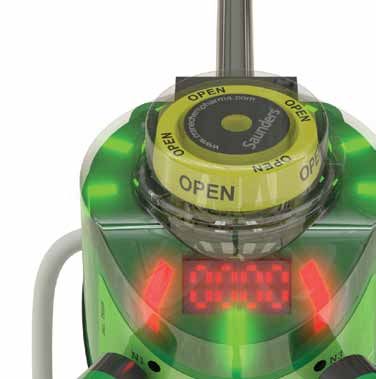
Saunders® I-VUE Sensor Key Features and Benefits
The Saunders® I-VUE is an intelligent valve sensor designed specifically for
aseptic diaphragm valve applications in the Life Science industry. Compatible
with Point-to-Point (P2P), AS-i, and DeviceNet control systems, the Saunders®
I-VUE offers substantial benefits over standard switch controls.
Saunders® I-VUE Key Features
Enhance Reliability and Accuracy with Saunders® I-VUE solid
state continuous sensing technology that provides precise position
readings for the entire valve range from 0.25” to 4.00” (DN8 to DN100).
Simplify Installation by utilizing automated valve calibration
without opening the IP67 rated polycarbonate sensor enclosure,
reducing set up times to 3 minutes or less.
Lower Maintenance Costs by applying factory or user defined
device settings to monitor valve cycle count and end point tolerance
limits, preventing false alarms and unnecessary diaphragm
replacement.
Saunders® I-VUE Sensor Key Benefits
With fully potted solid state electronics to protect against moisture and vibration, and no contacting parts to fail, the Saunders®
I-VUE is built to provide many years of accurate valve position sensing. The Saunders® I-VUE advanced electro-magnetic sensing
technology provides accuracy of less than 0.2mm (0.008”) and is designed to be used on valves from 0.25” – 4.00” (DN8-DN100)
with reliable, repeatable results. Unlike conventional end point switches, thanks to the Saunders® I-VUE continuous sensing, valve
position is always known throughout the range of travel, allowing more accurate control even with variable process conditions.
The Saunders® I-VUE sealed IP67 and NEMA 4X rated polymer casing is compact, rugged, and does not require any dismantling
when commissioning the valve. When fitted with the high performance integral solenoid valve, open and closed positions can
be set via the network control system or at the unit in either manual or self-calibration modes in under 3 minutes, dramatically
reducing complexity and cost even in hard to reach installations.
The Saunders® I-VUE has a unique LED smart window display to assist in setting and programming the sensor and communicating
alarms. Diaphragm management and general maintenance is vastly improved as the Saunders® I-VUE can be programmed
either by date or by operation cycle count, preempting unnecessary diaphragm replacement. Programmable alarms are in
place for easy monitoring of valve and process status.
Please visit our Web-Based Drawing Library at: www.saundersdrawings.com for current database of drawings in PDF, 2D DWG, and 3D IGES formats.
2
www.saundersI-VUE.com
www.cranechempharma.com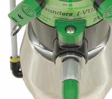
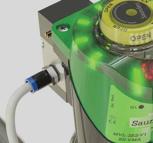
Saunders® I-VUE Sensor Features Overview
Ring of bright red and green
LEDs display valve position.
Visual Position Indicator
shows valve position even in
the event of power loss.
Illuminated Smart Window
display assists in programming
the sensor.
Robust all-polymer
enclosure is rated
NEMA 4X, IP67. Magnetic Buttons allow
calibration and programming
of Saunders® I-VUE without
opening enclosure.
Saunders® I-VUE direct
mounts on Saunders® S360
actuator. Compact adapters
available for Saunders® EC
Optional 24VDC integral and ECX actuators.
solenoid valve.
Please register your Saunders® I-VUE at: www.saundersI-VUE.com to access important
installation information, download Electronic Data Sheets (EDS), and receive notifications
of required firmware upgrades.
Please visit our Web-Based Drawing Library at: www.saundersdrawings.com for current database of drawings in PDF, 2D DWG, and 3D IGES formats.
3
www.saundersI-VUE.com
www.cranechempharma.com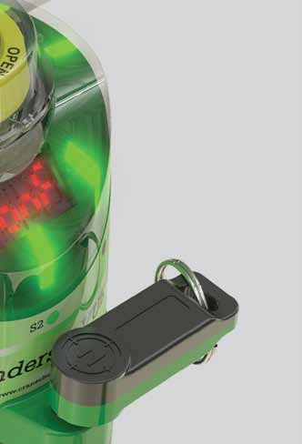
Saunders® I-VUE Sensor Operating Instructions

Saunders® I-VUE EZ-SET Feature

The Saunders® I-VUE is ready to install and operate as delivered. The EZ-SET
feature allows quick setting of the sensor without the need to open the
enclosure. The EZ-SET feature works with P2P and networking options fitted
with integral solenoid. Simply hold the black N side of the magnetic key against
the N3 magnetic button for three seconds, confirm the action by touching the
green S side of the magnetic key against the S2 button, and the valve will stroke
three times and set open and closed positions.

When Saunders® I-VUE is a part of a network using AS-i or DeviceNet, the sensor
can also be set from the control station. The Saunders® I-VUE can also be easily
set when a remote solenoid is employed.

Standard settings and alarms can be custom programmed at the sensor using
the magnetic key and buttons. These parameters can be programed at the
control station on units that are DeviceNet or AS-i enabled.

The Saunders® I-VUE will Default to Factory Settings Unless
Custom Programmed. These Factory Settings Include
Tolerances                           Factory Setting
 Open Position H                            20%
 Close Position L                           20%
Alarms                               Factory Setting
 Cycle Time                                 OFF
 Partial Counter                            OFF
 Worked Days                                OFF                                Please register your Saunders® I-VUE at:
 Date                                       OFF
 PNP                                        OFF                                          www.saundersI-VUE.com
 Solenoid                                   ON                                       to access important installation
Others                               Factory Setting
 Display                           PCot (Partial Counter)                      information, download Electronic Data
 Sleep Mode                                 OFF                               Sheets (EDS), and receive notifications of
 Self-Calibration                         3 Cycles
 Password                                NOT SET
                                                                                       required firmware upgrades.
 Total Counter                 Not Affected by Factory Reset
 DN Address                                  63
 DN Baude Rate                              125

Please visit our Web-Based Drawing Library at: www.saundersdrawings.com for current database of drawings in PDF, 2D DWG, and 3D IGES formats.

4
                                                                                                              www.saundersI-VUE.com
                                                                                                           www.cranechempharma.com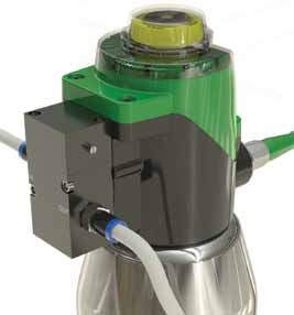
ode
ode
ode
Main
Main
Saunders® I-VUE Sensor
Main Menu
Menu
Operating
Menu Instructions
Revision
Revision 5.8
5.8 Revision 5.8
Main Menu
Revision 5.8
Saunders® I-VUE Fast Key Access
No
Fast Keys allow easy,No single-step operation of common functions. This includes Forced Solenoid, Self-Calibration, (EZ-SET), Demo
No
Mode, and also Reset
Password
Password
OK? of Password.
OK?
Password OK?
No
N1 - digit selector Yes Fast KeyFast
Fast
Key Access
Access
Fast Key
Key Access
N1
N3 -- digit
digit selector
Yes
N1 -- digit
N3
changes
digit changes
selector Yes Access
Password OK? S2 - confirms
N3 -- confirms
digit
digit changes
Function Button Button
Time ModeHold Time FunctionMode Display Message
Display Message
S2 digit
Button Display Message
Button Time Mode Function Display Message
S2 - confirms digit
Time Mode Function
Yes N3
N3
Fast Key Access
Force Solenoid
ForcedN3SolenoidN1
N3 3s
N1 Run Mode3 Force
seconds Solenoid Run
N1 3s Run Mode Force
(to Solenoid
energize the solenoid coil)
N3
N3
N3
Button
N3 Time N3 Mode N1 Function
3s Run Mode Display
(to energize the solenoid coil)
(to energize the solenoid coil) Message
N3 N3 N3
N3 S2
N3 Force Solenoid S2
N3
N3 N1
N3
N3
3s Run
N3 Mode (to energize the solenoid coil) 3 seconds
Self Calibration Setting 12 S2
N3 N3
N3 Self-Calibration N3
N3
N3 3s Run Mode Self Calibration Setting
12
1 2
N3
N3
N3
N3
3s
3s Run Mode seconds
(6
Run Mode Self
(run auto if
Calibration
setup)
(run auto setup) Run
Setting 12
N3
S2 (auto setup)
S2 (run auto setup) S2 N3
Back to
N3
S2
S2
S2 S2
S2
password reset) Back to
previous state
Back to
previous state
Self Calibration Setting1 2
Main Menu
previous state
Open Valve Tolerance
N3 3s
Closed Valve Tolerance Run Mode (run auto setup) N3
Demo Mode
Open Valve
Valve Tolerance
Tolerance RUN Mode
Open Closed Valve
Closed Valve Tolerance
Tolerance
N3 - toValve
Open change %
Tolerance S2 - to confirm your choice Demo Mode
Closed Valve Tolerance Run Mode Demo Mode Revision 5.8
N3 - to change %
N3 - to change %
S2
S2-- to
S2
confirm your choice
to confirm your choice N1 and N3 Run Mode (open
Demo
Run Mode3 seconds
(open
andMode
Back close
to
and close
for 3 sec)
state for 3 sec)
Run S2 for more than
(2 keys required)
3 seconds
previous
N1 & N3 3s (open and close for 3 sec)
N1 & N3 3s Reset Password
Closed Valve Tolerance N1 & N3 3s Reset Password
N3 Demo Mode Conf Mode Reset Password
ce N3 Run Mode (open and close for 3Conf Mode (when the display ask the password)
(when the display ask the password)
N3 Conf
sec) Mode
N1 & N3 3s
S2 3 seconds
(when the display ask the password)
Password Reset Run when N3 is actived for more then 3 sec.
Note 1: If I-VUE is set to work without solenoid (remote solenoid),
No
1: N1 and isN3 3 seconds
Enter
N3 Note Reset
If I-VUE set to work without
Password solenoid (remote solenoid), when N3 is actived for more then 3 sec.
Password Yes
Note 1: Ifthe HandisCalibation
set to workwill show solenoid
up, waiting for LLsolenoid),
and HL setup and
N3will return toforthe Runthen
Mode.
Password OK?
N3 Conf Mode I-VUE without (remote when is actived more 3 sec.
(If configured)
N3 thethe
(when Hand Calibation
display will show up, waiting for LL and HL setup Noand will return to the Run Mode.
ask the password) Fast
Note 2: Ifthe
there
Handis any alarm, will
Calibation the show
time to perform
up, waitingthe
forself calibration
LL and HL setupchanges
and willfrom 3 sec.
return to 6
to the sec.
Run Mode. N1 - digit selector Yes
Note 2: If there is any alarm, the time to perform the self calibration changes from 3 sec. to 6 sec.
N3 - digit changes
S2
Note 2: If there is any alarm, the time to perform the self calibration changes from 3 sec. to 6 sec.
S2 - confirms digit
S2 Button Time Mode Function
S2 Note 1: If I-VUE is set to work without solenoid (remote solenoid), when N3 is actived for more then 3 sec. N3
Force Solenoid
N1 3s Run Mode
N3 - to change time the Hand Calibation will show up, waiting for LL and HL setup and will return to the Run Mode. N3 N3 N3
(to energize the solenoid
N3
S2 -- to
to confirm
change your
time choice
Note 2: If there is any alarm,
Show Alarm the time Show
to perform
Actual the self calibration changes from 3 sec. to 6 sec.
N3 -- to
S2 to confirm
change your
time choice
S2 - to confirm your choice
N3
ProgrammingShow
the Saunders®
Configured
Alarm
Configured
I-VUE
Show Alarm
Counting
Show Actual
Counting
Show Actual N3 N3
N3 N3
N3 3s Run Mode
Self Calibration Sett
(run auto setup)
N3 Configured Counting
Program count Shows Actuation count S2
N3 Program
N1 - digit count
selector
S2 S2
Program count Shows Actuation
N3 - reset countercount
Show Alarm Show Actual N1
N3 -- digit
digit selector
changes Shows
N3 Actuation
S2 -- save
reset countercount
The Saunders® I-VUE can be programmed to configure a range of features
Open Valve Tolerance Closed Valve Tolerance
N1 - digit
digit changes
selector and quit Demo Mode
Configured Counting
N3
S2 -- confirms digit N3
S2 -- save
reset and
counter
quit This option counts and generates an alarm signal N3 - to change % S2 - to confirm your choice Run Mode (open and close for 3 se
N3 -- confirms
S2 digit changes
digit S2 - save and quit This option counts and generates an alarm signal
N3 S2 - confirms digit This option counts and generates an alarm signal N1 & N3 3s
Program and alarms
N3count
N3selector
based
Shows Actuation count on specific system or application requirements. This is N1 N3
N3 N3 Conf Mode
Reset Password
(when the display ask th
N1 - digit
N3 - resetYes
counter This option does not count and does not generate
N3 - digit changes This option does not count and does not generate
S2 accomplished
S2 - confirms
S2 - saveYes via the magnetic
and quit S2 key andN3 buttons, whilecounts
This option observing the
and generates an
an alarm
This signal
option
alarm does not count and does not generate
signal N3 N3
Note 1: If I-VUE is set to work without solenoid (remote s
S2 digit Alarm “ON”? Yes S2 N3 an alarm signal the Hand Calibation will show up, waiting for LL
S2 Alarm “ON”? S2 N3 an alarm signal Note 2: If there is any alarm, the time to perform the self
selections on the Smart Window Display.
S2 S2
Alarm “ON”?
N3 - to change condition This option counts but does not generate an alarm
No This option counts but does not generate an alarm
This option does not count and does
N3 -- to
to confirm
change your
condition S2
Thisnot
signal generate N3 - to change time
S2Yes choice No S2 option counts butS2does notchoicegenerate an alarm
- to confirm your Show Alarm Show Actual
N3
S2 -- to
to confirm
change your
condition
choice S2 No N3 S2 an alarm signal signal Configured Counting
S2 - to confirm your choice
N”? signal N3
Program count Shows Actuation count
N1 N3 N1 - digit selector
N3 - reset counter
The S2 Button accesses N1 - digit selector(“drills down”) a selection
N
N31 -- digit
changeselector
digit
in the
This option programming
counts but does not generate an alarm
N3 - digit changes
S2 - confirms digit
S2 - save and quit
S2 N1 - change
N3 digit selector signal
N3 N3
S2 -- confirms digit
digit clear worked days
N3
N3
ladder (nested menu S2 changeof
N3 -- confirms digitfunctions).
digit
S2 - confirms digit
clear workedThe
days N3 Button moves the selection
clear worked days S2 S2
Alarm “ON”?
Yes
S2 N3
N3
“cursor” down the ladder, and the N1 Button moves it up
N1 - digit selector
N3 - to change condition
S2 - to confirm your choice
No S2
N3 - change digit
Yes days
clear worked
S2 the ladder, Yes until the desired function is reached. When the
S2 - confirms digit
N3 -Yes N1 N3
N1 - digit selector
Alarm “ON”? Yes
N3 - change digit
S2 N3 -Yes S2 - confirms digit clear worked days
S2 Alarm “ON”? N3 -Yes N3 N3
N3 - to change condition desired parameter Show(function) is reached, the S2 Button
Alarm “ON”?
No Alarm S2 - No Yes
N3 -- to
S2Yes to confirm
change your
condition
choice No Show
ConfiguredAlarm S2 - No S2 S2 N3 -Yes
N3 - to confirm
change your
condition Show Alarm
S2 choice
S2 - to confirm your choice
N”?
accesses
No that option,
Configured
N3 -Yes
Configured while the
S2 - NoN1 and N3 Buttons will
N3 - to change condition
Alarm “ON”?
No Show Alarm S2 - No
S2 - to confirm your choice Configured
Show Alarm
again scroll through the
Change Date
Change
N1 - day
Change
Date options.
or month
Date
selector Pressing
Change Year
Change
N1 - digitYear the S2 Button
decreases N1 N3
Change Date Change Year
N3 S2 - No N1
N3 - day or month
change digit selector Change
N1
N3 - digitYear
decreases
increases
N1 - day or month selector N1 - digit decreases
Configured N1 -- confirms
day or month selector N1
S2 -- confirms
digit increases
decreases N3 N3 N3 - change digit N3 - digit increases
N3 confirms the selection. N3
S2
N3
S2 -
change
change
confirms
digit
digit
N3
N3
digit
digit increases
S2 - confirms S2 - confirms
N3 S2 - confirms
S2 - confirms S2 - confirms
Change Date Change Year S2 S2
Alarm ON?
Yes S2 S2
N1 - day or month selector N1 - digit decreases
N3 - S2
change digit YesN3 - digit increases S2 S2
N3 - to change condition
No Day Month Year
Programming Yesand alarm features can be deployed at
S2 - to confirm your choice
S2
S2 - confirms Alarm ON? YesS2 - confirms S2 S2
S2 Alarm ON? S2 S2
Alarm ON? N1 N3 N3 Partial Counter
N3 - to change condition
N3
S2 -- to
to confirm
N3 -- to
change your
to confirm
condition
change your
choice
condition
the user’s
No
No option, and Day they
Day Monthvary with the
Month
Year requirements
Year
N3
Total Counter
S2 choice No Day Month Year N3 N3 Valve Position
Yes your choice
S2 - to confirm S2 S2
N? pertaining to solenoid type, mode of feedback, and S2
Worked Days
N3 Partial Counter
N3 networking protocol.
N3Day Month Partial Counter Year The Saunders® I-VUE IOM Manual N3 - to change option
Partial Counter S2 - to confirm your choice
Total Counter
Total Counter
N3
providesTotal
easy-to-follow
Counter
Valve Position
steps for all functions, and includes N1 N3
N3 N3
artial Counter N3 Valve Position
N3 a flow chart
Worked asDaysa visual aid for programming the sensor.
Valve Position
N3 N3
tal Counter Worked Days S2 S2
Worked Days Typical Programming Logic N3 - to change condition
N3 N3
alve Position S2 - to confirm your choice
N3 - to change option N3 N3
N3
S2 -- to
orked
to confirm
N3 -- to
S2
change your
toDays
option
change your
confirm
choice
option
choice
Please refer to the Installation, Operating and Maintenance Manual for full instructions on mounting, calibrating, programming and N1 N3
N3 N3 N3 N3
S2 - to confirm your choice
operating the Saunders® I-VUE sensor which is available at: www.saundersI-VUE.com. N3
N3
5
Yes
S2 S2
Sleep ON?
N3
N3 N3 - to change condition N3 - to change time
N3 S2 - to confirm your choice No S2 - to confirm your choise
www.saundersI-VUE.com N1 N3
N3
N3 N3
www.cranechempharma.com
S2
S2
S2
N3
N3
N3
N3
Hold N1 for more
than 4 seconds until
“End” be displayed and
open/ closed led
N3 N3
N3 N3 indicator be lighted
S2
N3 - to change condition N3 N3
Saunders® I-VUE Sensor Technical Details
Saunders® I-VUE Technical Details
The Saunders® I-VUE has the ability to set end point tolerance up to 40%
of travel. This feature allows reliable feedback under variable process
conditions and/or fluctuating air supply. End point limit switches cannot
accommodate these variable conditions without false position indications
resulting in unnecessary alarms.
The solid state sensing technology used in the Saunders® I-VUE
provides sensitivity of .2mm (0.008”). This performance ensures accurate
performance on smallest valves. The Saunders® I-VUE Sensor is available as
a point to point sensor or as a sensor integrated into a network using AS-i
or DeviceNet communication.
Saunders® I-VUE Optional Integral Solenoid
Body: Anodized Aluminum or Stainless Steel
Type: Piloted, 3/2
Voltage: 24VDC 0.6W
Cv: 0.9 (0,8 Kv)
Flow Rate: 400 NI/m
Air Connections: 1/8” BSP
Manual Override: Standard
The Saunders® I-VUE Complies with the Following International Codes and Standards
Approvals P2P AS-i DeviceNet
NEMA 4X
IP66
IP67
CE
Please visit our Web-Based Drawing Library at: www.saundersdrawings.com for current database of drawings in PDF, 2D DWG, and 3D IGES formats.
6
www.saundersI-VUE.com
www.cranechempharma.com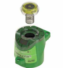
Saunders® I-VUE Sensor Technical Details

                                                       Saunders® I-VUE Sensor Technical Details

                                                       The Saunders® I-VUE has been engineered to compensate for the behavior
                                                       of diaphragm valves under multiple processing conditions including:
                                                       process, CIP and SIP, and varying operating air supply.

                                                       Valve Size Range:             0.25”–4.00” (DN8-DN100)
                                                       Temperature Range:            0°C to + 70°C
                                                       Sensing Technology:           Continuous sensing via five
                                                                                     electro-magnetic coils
                                                       Target:                       Composite ferrous magnet
                                                       Sensitivity:                  Less than 0.2mm (0.008”)
                                                       Position Indication:          Green LEDs - Open
                                                                                     Red LEDs - Closed
                                                                                     Physical position indicator
                                                       Feedback Options:             24VDC P2P
                                                                                     AS-i version 2.0 standard address
                                                                                     AS-i version 2.1 extended address
                                                                                     AS-i version 3.0 extended address (optional)
                                                                                     DeviceNet
                                                       Local Programming:            Via magnetic key
                                                       Remote Programming:           At control panel
                                                                                     (Networking versions only)
                                                       Standard Connection:          P2P with SOV: M12 5 pin
                                                                                     P2P without SOV: M12 4pin
                                                                                     AS-i: M12 4 Pin
                                                                                     DeviceNet: Mini 5 pin
                                                       Optional connections available include: pig tail with cable gland.

                                                       Saunders® I-VUE Construction
                                                       Connection Box:               Polycarbonate
                                                       Module Housing:               Polycarbonate
                                                       Cap:                          Polycarbonate
                                                       Seals:                        Buna N
                                                       Connector:                    Stainless steel
                                                       Fasteners:                    Stainless steel
                                                       Target:                       Composite ferrous magnet
        Saunders® I-VUE Power Consumption
          Type                               P2P - 24 VDC                 AS-i - 31.5 VDC                DeviceNet - 24 VDC
          I-VUE (solenoid OFF)             < 48 mA or 1.2 W               < 54 mA or 1.5 W                 < 48 mA or 1.2 W
          I-VUE (solenoid ON)              < 64mA or 1.5 W                < 64 mA or 2.0W                  < 64mA or 1.5 W

  Please refer to the Installation, Operating and Maintenance Manual for full instructions on mounting, calibrating, programming and
  operating the Saunders® I-VUE sensor which is available at: www.saundersI-VUE.com.
                                                                                                                                    7
www.saundersI-VUE.com
www.cranechempharma.com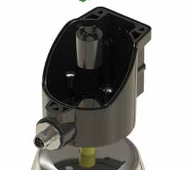
CRANE ChemPharma Flow Solutions®
                      Crane Process Flow Technologies Ltd.          Saunders® Sales Office
                                  Grange Road                         9860 Johnson Road
                          Cwmbran, Gwent NP44 3XX                 Montgomery, Texas 77316
                               UNITED KINGDOM                        Tel: +1 936 588 8360
                             Tel: +44 163 348 6666                   Fax: +1 936 588 8302
                             Fax: +44 163 348 6777
                                                www.saundersI-VUE.com
                                               www.cranechempharma.com

       Please register your Saunders® I-VUE at: www.saundersI-VUE.com to access important installation information,
              download Electronic Data Sheets (EDS), and receive notifications of required firmware upgrades.

CRANE Process Flow Technologies SPRL/BV             CRANE ChemPharma Flow Solutions                   CRANE Process Flow Technologies (India) Ltd
         Avenue Franklin No. 1                              4444 Cooper Road,                           Solitaire, 5th & 6th Floor, S. No. 131/1+2 ,
        Wavre, B-1300 , Belgium                        Cincinnati, Ohio 45242 U.S.A.                     ITI Road, Aundh, Pune - 411007, India
          Tel.: +32 10 8184 44                             Tel.: +1 513 745 6000                                  Tel.: +91 20 3056 7800
         Fax.: +32 10 8184 58                             Fax.: +1 513 745 6086                                   Fax.:+91 20 3056 7812

                                                                                                                                            CP-SAUNDERS-I-VUE-BU-EN-L15-2012-11-16 -AF
                                                                               www.flowoffluids.com

                                                              brands you trust.

                           CRANE ChemPharma Flow Solutions Include: Pipe - Valves - Fitting - Actuators - Pumps

  Crane Co., and its subsidiaries cannot accept responsibility for possible errors in catalogues, brochures, other printed materials, and website
  information. Crane Co. reserves the right to alter its products without notice, including products already on order provided that such
  alteration can be made without changes being necessary in specifications already agreed unless otherwise indicated. All trademarks in this
  material are property of the Crane Co. or its subsidiaries. The Crane and Crane brands logotype (DEPA®, ELRO®, Krombach®, PSI®, Resistoflex®,
  ResistoPure™, Revo®, Saunders®, WTA® and XOMOX®) are registered trademarks of Crane Co. or its subsidiaries. All rights reserved.

                                  © 2012 CRANE ChemPharma Flow Solutions®, www.cranechempharma.com
You can also read