Characteristics of popular photon beam collimators
←
→
Page content transcription
If your browser does not render page correctly, please read the page content below

Journal of Physics: Conference Series

PAPER • OPEN ACCESS

Characteristics of popular photon beam collimators
To cite this article: Shidong Li 2019 J. Phys.: Conf. Ser. 1305 012060

View the article online for updates and enhancements.

 This content was downloaded from IP address 46.4.80.155 on 18/01/2021 at 05:32
10th International Conference on 3D Radiation Dosimetry (IC3DDose) IOP Publishing
IOP Conf. Series: Journal of Physics: Conf. Series 1305 (2019) 012060 doi:10.1088/1742-6596/1305/1/012060

Characteristics of popular photon beam collimators

 Shidong Li
 Department of Radiation Oncology, Temple University, 3401 North Broad Street,
 Philadelphia, PA 19140

 E-mail: Shidong.Li@tuhs.temple.edu

 Abstract. Purpose: To compare the physical and dosimetric aspects of radiation beam
 collimation systems that may affect the stereotactic radiosurgery and radiotherapy of small
 lesions. Methods: Gamma knife (GK) cones, Cyber-knife Iris/InCise collimators, popular
 Varian and Elekta multi-leaf collimators (MLCs) were theoretically analyzed. Leaf-edge effects
 (Inter- and intra- leaf leakages, field penumbras, and dosimetric leaf gap - DLG) and transmission
 through some collimators were measured with ion chambers and films in phantoms and
 electronic portal imagers in an extended distance. GK plans and IMRT/VMAT plans were
 generated for ten patients and conformity index (CI) and dose drop (DD) from target to 5-mm
 ring were compared. Results: New MLCs have improved field shaping conformity, reduced
 transmission but not field penumbra and DLG. The measured DLG changed with time of usage
 and varied across the field. GK plans had better CI and DD for small lesions of < 1 cm while
 MLC-based VMAT/IMRT plans improved CI for large lesions of > 2 cm. Conclusions: New
 thinner and taller MLCs have improved the field shaping conformity and transmission but not
 leaf edge effects. Cone-based irradiation is still the best to small lesions of < 1 cm while
 VMAT/IMRT using new MLCs provide more conformal dose to irregular target usually with
 size of > 2 cm.

1. Introduction
I should like to begin by describing MLC leaf-edge effects on delivered dose on which we have some
theoretical study twenty-two years ago [1]. As you know that MLC has made IMRT [2] and VAMT [3]
possible and new collimation systems have been designed in recent years. To select a machine to treat
intracranial and extracranial lesions, there are extensive options of GK, cyber knife, tomo-type and c-
arm-type linear accelerators equipped with MLCs for 3DCRT, IMRT, VMAT, SRS and SBRT.
Understanding the characteristics of equipped collimators could be the key factor in purchasing the
machine. This pilot study is by no means exhaustive to cover all clinical aspects of MLCs but the
dosimetric impacts or differences of MLCs.

2. Characteristics of Popular Collimation Systems

2.1 Summary of popular Collimation Systems
Table 1 listed the technical specifications of some popular collimation systems with reference [4] for
Gamma Knife, [5] [6] for Cyber Knife, [7] for Varian MLC and [8] for Elekta MLC. There are Siemens
MLC, Tomotherapy MLC, Brainlab micro MLC, and other MLCs. To address the clinical impacts, an
algorithm in round-end leaf control was described in subsection 2.2. Measurements of leaf edge effects

 Content from this work may be used under the terms of the Creative Commons Attribution 3.0 licence. Any further distribution
 of this work must maintain attribution to the author(s) and the title of the work, journal citation and DOI.
Published under licence by IOP Publishing Ltd 1
10th International Conference on 3D Radiation Dosimetry (IC3DDose) IOP Publishing
IOP Conf. Series: Journal of Physics: Conf. Series 1305 (2019) 012060 doi:10.1088/1742-6596/1305/1/012060

 and their influences on treatment plans were explored in other sections.

 Table 1. Specifications of Popular Collimators (all Length in mm, angle in degree,% dose to that of machine specific reference*
 Machines Gamma Knife Cyber Knife Varian Machines Elekta Machines
 Type of Collimation Cones Iris MLC InCise MLC HD 120 Millenium 120 Standard MLC B.M. MLC Agility MLC MLCi/i2
 Max Static Field Size (mm) 18 / 16 60 100x120 400x220 400x400 400x400 160 x 210 400x400 400x400
 Leaf Travel Range (mm) NA (0, 30) (-60,60) (-200, 201) (-200,201) (-200,201) (-105, 105) (-150,200) (-125, 200)
 Maximal Leaf Speed (mm/s) NA 25 25 25 25 30 30 20
Maximal Carriage Speed (mm/s) NA NA NA 12 12 12 NA 35 20
 Source to Leaf Tip Level (SCD) 504 504 505 427.8 349.3 335.5
 ource to Collimeter Base (mm) 165/140-198 400 400 538 538 535 465.3 407.7 373
 Prism- Cnt 32 pairs 2.5 Cnt 40 pairs 5.0
 Leaf width (mm) N/A Shaped 3.85 Out 28 pairs 5.0 Out 20 pairs 10 40 pairs 10 40 pairs 4.0 80 pairs 5.0 40 pairs 10
 Collimator/Leaf height (mm) 60/120 60 90 68 - 69 67 60 75 90 75/82
 Leaf end radius or shape (mm) focus straight 3-flat 160 80 80 122 170 150
 Tongue & groove offset NA NA NA 0 0.4 0.4 0 0 0.6/0
 Leaf material W W 95% Cu 5% W 95% Cu 5% W 95% W 92.5% W 92.5 % W 95% , Ni 3.75%, Fe 1.25%
 Density (g/cm3) 19.3 18 18 18.0 -18.7 17.15 - 17.85 17.15 - 17.85 18
 Average transmission
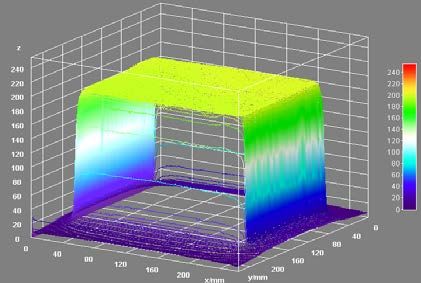
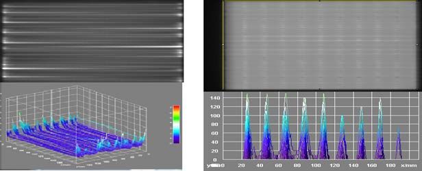
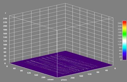
10th International Conference on 3D Radiation Dosimetry (IC3DDose) IOP Publishing
IOP Conf. Series: Journal of Physics: Conf. Series 1305 (2019) 012060 doi:10.1088/1742-6596/1305/1/012060

2.3 Leaf Edge Effects (LEEs) on Dose Delivery
LEEs are sensitive to the submillimeter leaf position uncertainties. Thus, measurements are required to
quantify LEEs particularly for weariness of extensive use or recalibration. Figure 3 and 4 demonstrate
that measured LEEs using an on-board electronic portal imager (EPI) after geometric conversion to SAD
and dosimetric renormalization to the ion chamber doses at d max = 16 mm. The penumbras at 10 cm
depth can be determined with scans in a water tank or films in a solid phantom.

 (a) (b)

 (c) (d)
 Figure 3. EPI uniform response to 6X 21x16 cm open field (a), % transmission in a closing field (b),
 % interleaf leakage distribution (upper) and 3D plot (c), and normalized intensity distribution in
 dynamic Picker Fence irradiation (upper) and 10 time % end leakage by subtracting closing field
 intensity (d).

 3
10th International Conference on 3D Radiation Dosimetry (IC3DDose) IOP Publishing
IOP Conf. Series: Journal of Physics: Conf. Series 1305 (2019) 012060 doi:10.1088/1742-6596/1305/1/012060

Figure 4. Measured cross-plane penumbras 4.8 mm vs in-plane penumbras 4.0 mm for a 1x1 cm field
using a vertically mounted pinpoint ion chamber scanned at SSD = 90 cm and depth = 10 cm.

Notice that high interleaf leakage at some points (Fig. 1b) may affect measurement of DLG. A pin-point
chamber was placed at the points of interest and doses from 2, 5, 10, and 20 mm width sliding window
through a 20-cm square field for Agility (AG) MLC and 21 x 16 cm field for beam modulate (BM) MLC
at 90 cm SSD. For 6-MV X-ray beams, the DLG are 0.26, 0.18, and 0.07 mm for BM MLC and 1.7, 0.5,
and 1.1 mm for AG MLC. Similar measurement was performed on Varian machine with HD 120 MLC
with the DLG of 0.39 and 0.27 mm for 6X and 6X FFF beams, respectively. However, the DLG in
Eclipse TPS system had to be 1.1 mm in order to match the plan dose with delivered dose [6]. Both
DLG variations across the fields and dose calculation differences support the author’s question for the
concept of DLG to be briefly described in the next subsection.

2.4 What is the “DLG”
The concept of DLG was introduced by LoSasso et al [11] for adding intra-leaf leakage in dynamic
IMRT fields. DLG was measured by the distance of the point with a zero dose from linear extension of
the plot of dose vs sliding window widths. The dose for zero width of the sliding window should be the
convolution of the radiation intensity I(x,y) with the additional scattering and transmission kernels at
the leaf ends to the depth of interest. The subtracted profiles for a field defined by those focus jaws from
the profiles for the same field defined by the MLC could provide the kernel and that could be
approximated by two rectangle triangles (referring to Fig 2(d) for two end edges): one transmission
through the leaf tip with a base size of τ and the height of k τ and the other mainly for more scattering
from the leaf tip into the open area with a base size of σ and height of k σ . Integration provided:

 DLG(x,y) = (k τ τ+ k σ σ) I(x,y) / I o

Where k τ and k σ ∈ (0,1) were ratios of the transmission and scattering peaks to the dose at CAX. If k
were a constant, DLG would only change with radiation intensity such as FFF beams. Changes of the
leaf end positions and the sides of the leaf as well as dose rate (MU) at the location (X,Y) could all affect
the amount of scattering and transmission. Thus, a constant DLG does not truly represent LEEs and
measured inter- and intra-leaf leakages should be included in the TPS commissioning.

3. MLC effects on Treatment of Small Lesions

3.1 Field Shape Conformity Using Various Collimators

 4
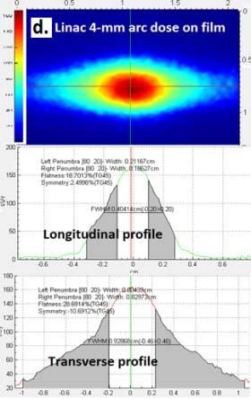
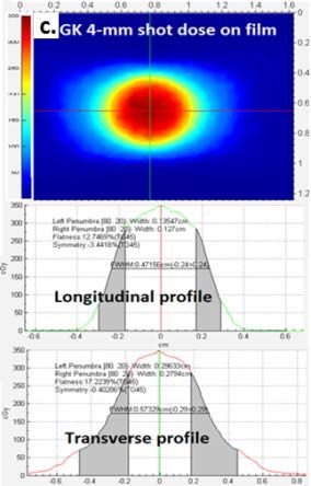
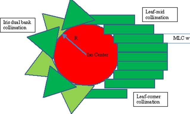
10th International Conference on 3D Radiation Dosimetry (IC3DDose) IOP Publishing
IOP Conf. Series: Journal of Physics: Conf. Series 1305 (2019) 012060 doi:10.1088/1742-6596/1305/1/012060

 Figure 5. Illustration of MLC shaped
 circular fields by an Iris MLC (left half)
 or a regular MLC using mid or corner
 matching to the spherical or circular
 shape target. The field conformity index
 (CI) = open area/target area.

 3 /
 ℎ ≈ = 0.95. = 4 ∑ =1 √ 2 − 2 2 /( 2 ). For R= 20-mm target, CI are

0.90, 0.79 and 0.55 by using a MLC with width w = 2.5, 5.0 and 10 mm, respectively.

3.2 Actual Coverage for small spherical targets using Cones or MLCs
Coverage of small spherical targets by the prescription does using single GK shot, MLC shaped field or
arc were validated with film dosimeters. GK cones sizes are circular shapes while accelerators can
change the field shape and size through adjusting leaves. The dose distributions from available GK shots
and beam-modulate (BM) and agility MLC (AM)-shaped fields and arcs using Gafchromic EBT3 films
placed within a spherical phantom as shown in Fig. 6.

 Figure 6. A spherical phantom
 setup on GK 4C unit (a) and on an
 Linac tabletop with a custom
 precise support (b), the measured
 dose distributions and orthogonal
 profiles from a 4-mm GK shot (c),
 and the dose and profiles for a
 MB-shaped 4x4 square full arc (d)
 are presented here for
 comparison.

 5
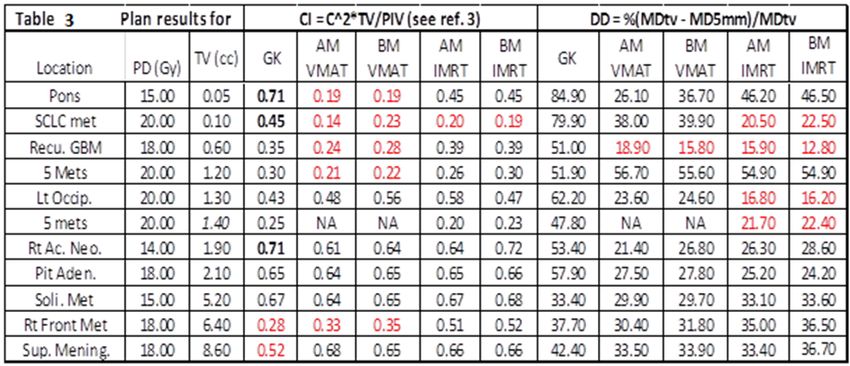
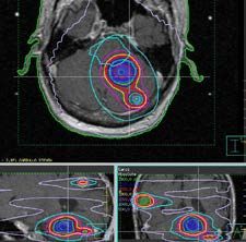
10th International Conference on 3D Radiation Dosimetry (IC3DDose) IOP Publishing
IOP Conf. Series: Journal of Physics: Conf. Series 1305 (2019) 012060 doi:10.1088/1742-6596/1305/1/012060

 Table 2. Results of the measured penumbra, FWHM, symmetry, and peak dose values.
 Size Trasnverse Transverse Transverse Transverse Longitudinal Longitudinal Longitudinal Longitudinal Max Dose
 Mode
 (mm) Penumbrac) FWHMd) Flatness % Symmetry % Pennubra FWHM Flatness % Symmetry % (cGy)e)
 4 2.7 5.6 12.3 0.1 1.2 4.7 9.4 1.1 362
 GK 8 4.2 10.9 9.3 0.7 1.4 9.0 7.7 2.1 389
 a)
 shot 14 6.6 18.5 10.2 8.0 1.8 15.7 5.2 5.3 403
 18 8.2 23.5 7.1 0.1 1.9 20.0 4.3 3.8 413
 4 8.1 8.8 21.8 8.2 2.1 4.1 16.2 8.8 177
 BM
 b) 8 12.5 13.2 20.0 6.2 2.4 7.5 12.1 3.3 363
 arc
 16 15.5 24.8 14.0 0.1 2.5 15.5 8.6 3.7 424
 5 8.3 9.2 19.2 2.5 2.6 4.6 17.8 2.6 250
 AM
 b) 10 12.8 15.8 16.0 4.4 2.9 9.5 10.2 0.2 383
 arc 420
 20 14.4 30.8 14.5 0.6 2.9 19.8 6.0 1.8
 4 2.5 4.7 16.4 3.4 1.7 3.8 15.4 0.9 192
 BM
 8 3.4 8.5 14.3 6.2 2.4 7.4 12.3 4.1 362
 Fieldb)
 16 3.6 16.5 9.1 0.3 2.5 15.5 8.4 2.2 421
 5 3.0 5.4 19.4 0.8 2.4 4.8 18.2 0.5 279
 AM
 10 3.2 10.5 10.4 3.0 2.6 9.6 8.7 1.7 372
 fieldb)
 20 3.4 20.9 7.0 0.8 2.8 19.7 6.2 1.9 420
a) All GK shots used the same treatment time of 1.25 min for dose of ~410 cGy from 18-mm helemt.
b) All beam-modulate (BM) and agility MLC (AM) arcs/fields were irradiated with 600 MU of 6X.
c) Transverse Penumbras for shots and arcs were larger than corresponding longitudinal penumbras.
d) Full-Width-Half-Maximum (FWHM) were larger than longitudinal values by beam overlapping.
e) The maximal doses on the films were the maximal dose value without using smooth filtering.

3.3 Comparison of patient SRS plans
We expanded our study to treatment planning for complete coverage of various targets while sparing
nearby function structures. Deformable image registration software (Velocity, Varian Inc.) was used to
transfer patients’ GK plans with cranial volume MRI, structures, and dose matrix. Patient CT scans were
then used for dose calculation for non-coplanar beams or arcs in Pinnacle P3RTP system. If there was
no head CT scans, we had overwritten MRI with uniform density of 1 g/cc as Fig. 7.

Figure 7. A single iso IMRT/VMAT plans and DVHs (left penal) for 6 lesions with sizes from 0.2 to
3.2 cm3 and prescription dose (PD) of 20 Gy and two iso IMRT/VMAT plans and DVHs (right penal)
for another patient with a right acoustic neuroma for PD of 15 Gy and a small recurrent GBM in the
right parietal lobe for PD of 20 Gy. Dash/Solid DVH lines are for IMRT/VMAT plans, respectively. All
plans had coverage of > 95% and optimized conformity index defined as C.I. = coverage2 x Target
Volume / Prescription Isodose Volume [12] and the peripheral dose drop-off: DD = % (mean dose of
TV – mean dose of 5-mm margin ring) / mean dose of TV.

The results for tested 11 cases (some cases had multiple lesions as a single target) were listed in Table
3 (AM for agility MLC and BM for beam modulator MLC) with red numbers indicating poor values in
a standard SRS treatment. For small lesions (TV < 1 cc or size of
10th International Conference on 3D Radiation Dosimetry (IC3DDose) IOP Publishing
IOP Conf. Series: Journal of Physics: Conf. Series 1305 (2019) 012060 doi:10.1088/1742-6596/1305/1/012060

cm). As we already know if Varian HDMLC or Elekta dynamic MLC with 2.5 mm leaf width are used,
CI would be further improved.

4. Conclusion
New MLCs had improved field CI but leaf edge effects (LEEs) varied significantly with a long-time
usage and/or recalibrations as well as changing across the fields particularly for the new FFF beams.
Theoretical comparisons and experimental verification are both useful in quantification of LEEs and
the LEEs made GK still the best choice for small brain lesions ( 2 cm. DLG concept was created to compensate differences in planning
commissioning using the profiles of beams shaped with the focus jaws while real delivered
IMRT/VMAT beams with the edges shaped by rounded leaf ends. Thus, conceptually, DLG should not
be used if the measured LEEs can be included in the next generation planning systems.

5. Acknowledgement
This research was partially supported by a pilot grant from Elekta Inc.

6. References
[1] Li S et al 1996 Int. J. Rad. Oncol. Biol. Phys. 36 398
[2] Bortfeld T R et al 1994 Int. J. Rad. Oncol. Biol. Phys. 28 723-30
[3] Yu C X 1995 Phys. Med. Biol. 40 1435-49
[4] Novotny J et al 2008 J. Neurosurg. 1009 8-14
[5] Echner G G et al 2009 Phys. Med. Biol. 54 5359-80
[6] Varian Inc. 2014 A comparison of EDGE Radiosurgery and CyberKnife M6
 https://www.varian.com/sites/default/files/resource_attachments/EDGEvsCK_RAD10325_Apr20
 14_secured.pdf
[7] Kim J et al 2018 Phys. and Imaging in Rad. Onc. 5 31-6
[8] Elekta Inc. 2017 Specification of Beam Modulator and Agility MLCs
[9] Boyer A L and Li S 1997 Med. Phys. 24 757-62
[10] Boyer A et al 2001 AAPM Report No. 72 Medical Physics Publishing, Madison, WI, USA
[11] LoSasso T et al 1998 Med. Phys. 25 1919-27
[12] Paddick I 2000 J. Neurosurg. 93 219-22

 7
You can also read