Colias IV: the Affordable Micro Robot Platform with Bio-inspired Vision - Core
←
→
Page content transcription
If your browser does not render page correctly, please read the page content below
TAROS2018, 020, v2 (final): ’Colias IV: the Affordable Micro Robot Platform with Bio- . . .   1

 Colias IV: the Affordable Micro Robot Platform
             with Bio-inspired Vision

     Cheng Hu1[0000−0002−1177−2167] , Qinbing Fu1[0000−0002−5726−6956] , and
                      Shigang Yue1[0000−0002−1899−6307]

    Lincoln Centre for Autonomous Systems Research, University of Lincoln, UK,
                        {chu, qifu, syue}@lincoln.ac.uk

       Abstract. Vision is one of the most important sensing modalities for
       robots and has been realized on mostly large platforms. However for
       micro robots which are commonly utilized in swarm robotic studies, the
       visual ability is seldom applied or with reduced functions/resolution,
       due to the high demanding on the computation power. This research has
       proposed the low-cost micro ground robot Colias IV, which is particularly
       designed to meet the requirements to allow embedded vision based
       tasks on-board, such as bio-inspired collision detection neural networks.
       Numerous of successful approaches have demonstrated that the proposed
       micro robot Colias IV to be a feasible platform for introducing visual
       based algorithms into swarm robotics.

       Keywords: micro robot, bio-inspired, vision, collision detection, low-
       cost

1    Introduction

Vision is one of the most important sensing modalities for autonomous robots
since it provides the abundant and reliable information about the surrounding
environment. Thanks to the development in computer vision technology, many
large-scale robots are taking advantage from vision sensors and also the most
advanced vision algorithms [1].
    On the other hand, small-scale robots, especially micro robots that are
usually employed in the swarm robotic research, can hardly benefit from visual
sensing. Even though the growth of interest in swarm robotics has brought
us a wide range to choose from [2–6], there is still no optimal design for
all desires. One of the greatest challenges is the trade-off between limited
computational resources on-board and the requirements for image processing
in real-time. The lack of vision inputs for swarm robotics has become a major
concern for researchers recently. For example, the E-puck [2], Swarm-bot [3] or
mROBerTO [4] are short of RAM size or sufficient CPU frequency. On the
other hand, for those robots whose CPU are strong enough, they are usually
oversized for swarm scenarios, such as Kobot [5], Wolfbot [6] and Khepera III.
The comparison of related robot platform are illustrated in table 1.
2   TAROS2018, 020, v2 (final): ’Colias IV: the Affordable Micro Robot Platform with Bio- . . .

                 2

                      Table 1: The Compare of Cutting-edge Robot Platforms with Image Sensors
                                    Kobot     KheperaIII E-puck Swarm-Bot mROBerTO Colias IV
                      CPU(MHz)       200          600       64      40         16        180
                         RAM         32M          32M       8K    648K        32K       256K
                        cost(↔)      800         2000       580    500         50*       80*
                     diameter(cm)     12           7        7.5   12.7         2.2        4
                     sensor types      4           7         4      4           7         6
                     autonomy(h)      10           1         1      3         1.5-6      1.5
                        remarks   Undeveloped discontinue                    *parts     *parts

                     For micro robots, suitable vision based algorithms should be selected and
                 applied [2, 7]. For example, the bio-inspired collision detection model Lobular
                 Giant Movement Detector (LGMD) inspired from locust visual neurons [8, 9].
                 Recently, the LGMD neuron has been modelled into computational algorithms
                 for autonomous vehicles [10–12]. However, due to the requirements on hardware
                 resources for image processing, the available robotic platforms or workaround
                 approaches are unsatisfactory: either too large [10], too expensive [11], or can’t
                 get rid of the connecting with a host device (wire or wirelessly) to process the
                 vision model [12]. These inconveniences prevent this promising visual model to
                 be applied in swarm robotic researches for further study. An affordable micro
                 robot platform that is small enough and can work independently is necessary.
                     In this paper, we propose a novel design of micro robot Colias IV to satisfy
                 mentioned requirements, which is an affordable hardware platform mainly deals
                 with visual tasks. As an upgrade version of previously develop micro robot
                 Colias [13] that is a differential driven ground robot with modular design,
                 the circular footprint occupies only 40mm in diameter. The new Colias IV is
                 additionally featured with an strong ARM Cortex M4 processor, a tiny VGA
                 camera, two digital microphones, one 9-axis motion sensors and various of
                 other sensing modules. To develop algorithms on the platform easily, software
                 packages are provided, including the motion planning and controlling strategies,
                 a friendly embedded programming environment and remote user accessibility
                 through extension modules. The bio-inspired collision detection algorithm called
                 Embedded-LGMD(ELGMD) and other related visual neural networks have been
                 successfully realized on this micro robot, which shows its practicability on
                 conducting vision based tasks autonomously.

                 2     The Assembly of Colias IV

                 The designed micro robot platform is based on three primary objectives: 1) to
                 realize middle-strength computation tasks including low-level image processing
                 autonomously, 2) to achieve better modularity so that each part has certain
                 features and functions that can work independently, and 3) to maximize the use
                 of space to save as much space occupation as possible.
                     As a result of the objectives, the robot is composed of three modularized
                 layers that provide different functions, namely the Colias Basic Unit (CBU),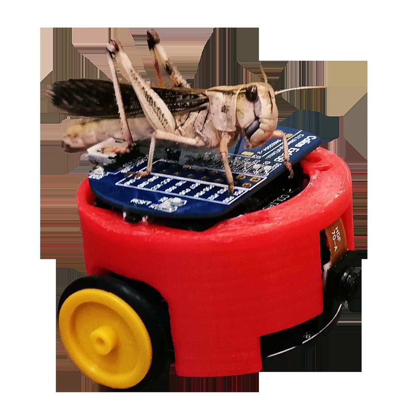
TAROS2018, 020, v2 (final): ’Colias IV: the Affordable Micro Robot Platform with Bio- . . .   3

                                                                                 3

        Colias Extension Unit
             (Bluetooth)

         Colias Sense Unit

          Colias Basic Unit

                                          1cm

                                (a)                            (b)
Fig. 1: (a)The Colias IV robot with CEU (Bluetooth) board attached, showing the
modules’ connections. The battery is located between the CSU and CBU; (b) A Colias
IV coated with a 3D-printed shell and CEU (USB-serial). An adult locust is standing
on the robot to compare the size.

the Colias Sensing Unit (CSU) and the Colias Extension Units (CEU). The
CBU serves preliminary robot features such as motion, power management
and some basic sensing. The CSU provides the high-level sensors such as
motion sensors and camera towards better programming environment with
image processing. Robot formed by CBU and CSU is sufficient for most
of the experiments. Furthermore, CEU provides specialized features such as
connectivity and illumination. The overall weight of Colias IV is 40 - 60 g,
varied according to different extensions. The hardware architecture of Colias IV
is illustrated in figure 2.

2.1   The Colias basic unit (CBU)
The Colias basic unit (CBU) is a upgraded version of previous Colias robot
started in 2013 [13], which is a light weight robot designed for swarm
applications. It is one of the smallest and cheapest micro-robots in this field.
CBU employs a circular platform with a diameter of 40 mm. It serves basic
sensing, motion generation and power management. The schematic design of the
CBU is illustrated in figure 2, and a photograph of CBU is shown in figure 3.

Micro Processor The purpose of CBU is basic motion control and sensing,
thus the primary consideration for choosing the processor is more of stability and
power-efficiency but not computation speed. The AVR series micro-controller
ATMega168P from Atmel is selected to meet these requirements. It is an 8-bit
micro-controller running at 8 MHz, equipped with 16 KBytes Flash, 1 KByte
RAM. It has 24 IO pins supporting analog-digital converter and serial ports.
   The application program inside the CBU’s is arranged with an infinite
loop. In the determined duty cycle of approximately 2 ms, the micro controller
manages to update a specific area of RAM as a register map. The register map
maintains the CBU’s system status including sensor data, LED configuration,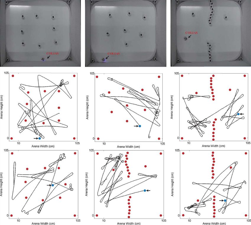
4   TAROS2018, 020, v2 (final): ’Colias IV: the Affordable Micro Robot Platform with Bio- . . .

                 4

                                                    Connect To Colias Extension Units

                                Power                          SPI &                        External
                                 3.3V   GPIOs                 SD Card              Debug     CPtP*                     I2C

                                                                                                                                 Motion
                                            Flash Memory                SPI Host           UART          I2C Host                Sensor
                                                                         JTAG                          DMA                   SCCB
                                           Microphone Right                                            REQ
                                                                         /SWD            DMA                    D      Data [7:0]
                                                                                       Controller       Data    C
                                           Microphone Left              I2S Host                                        PIXCLK           C
                                                                                                                M                        A
                                                                                                                        HSYNC
                                                                                                                I       VSYNC            M
                                                RGB LED                  Timer
                                                                                                                                         E
                                                                                           SRAM                          Clock           R
                                                                                                            MCO
                                                                                                                                         A
                                                                        GPIOs
                                             GPIO Devices                             STM32F427             UART
                                           (LEDs & Buttons)

                                                                  Colias Sense Unit

                                                Power
                                                                                                    Interrupt       Event IO        CPtP**
                                                3.3V & 3.7V

                                                              3x LEDs

                                                                                                          Event &
                                                                                                A                              UART
                                                          2x Ligt Sensors                                 Interrupt
                                                                                                                             Interface
                                                                                                D        Generator
                                                          3x IR Bumpers
                                                                                                C
                                                          1x IR Receiver
                                                                                                                         User
                                                   Motor Left                                   Motion               Registers Map
                                                                     H-Bridges                 Controller
                                                  Motor Right
                                                                                                            Atmega 168

                                 USB                Power
                              Charger                                                      Lithum Battery 3.7V 320mAh
                                                  Management
                                 5.0V
                                                                            Colias Basic Unit

                 Fig. 2: The Colias IV block diagram, showing the CBU and CSU architecture.
                 *CPtP is a reliable data transmission protocol that utilizing the UART as the physical
                 layer.

                 motion configuration and also system information. There is a separate interrupt
                 handle to decode and response to incoming control messages from CSU or other
                 higher level modules.

                 Environment Sensors The CBU is equipped with three kinds of sensors,
                 which are short range infra-red (IR) proximity sensors facing front, ambient
                 light sensors facing ground, and one long range IR receiver towards back.
                     The short range IR sensors (bumpers) are commonly used to indicate real
                 collisions. Each bumper has a IR emitter and a receiver towards the same
                 direction. Confirmation of collision is relied on the strength of received signal.
                 There are three bumper sensors facing front separated by 30➦. Their average
                 detection distance is 20 mm, which is also influenced by the light absorbing
                 character of the obstacle (figure 4a). The ambient light sensors are responsible
                 to measure light intensity within the spectrum of visible light with a photo-
                 transistor. They are mounted towards the ground on both sides of the robot,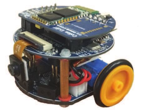
TAROS2018, 020, v2 (final): ’Colias IV: the Affordable Micro Robot Platform with Bio- . . .   5

                                                                                  5

Fig. 3: The photo of CBU from both sides with wheels and battery removed, indicating
several major components. In the bottom view, notice that the bottom LED that also
acts as the front pin stand.

which enable the robot to follow patterns on the ground, or react to the
surrounding illumination status. There is a long range IR receiver mounted
to the back, which is applied to receive signals from IR remote controller and
trigger actions accordingly. This feature improves the efficiency when conducting
experiments on multiple robot agents.

Locomotion The Colias IV employs differential driving method with two mini
geared DC motors. Each motor is driven through a H-bridge using pulse width
modulation (PWM) for power tuning. To support the robot with only two wheels,
the front LED is used as auxiliary fixed point stand, as indicated in figure 3.
The tested performance of speed tuning is shown in figure 4b with battery
conditions of full charged and normal levels. Due to the compact design that
prohibits encoders to be mounted on-board, the rotation speed of wheels can
not be measured directly. However the attitude of the robot can be estimated
through motion sensors described in section 2.2.
    Contributed by the high gear ratio (136:1) and lightweight of the robot
load (50g), the acceleration process could be achieved in several milliseconds.
The dynamics of the motor is normally not taken into consideration when
modelling the motion. The kinematics of the robot motion is described as a
simple differential driven model. Let vl and vr donate to the left and right wheel
velocities, we got the equation to represent the desired motion at any moment:
                                      l
                               ω(R + ) = vl                               (1)
                                      2
                                      l
                               ω(R − ) = vr                               (2)
                                      2
where ω is the angular velocity of the robot body, l is the distance between
the wheels and R donates the distance between the midpoint of the wheels and
Instant Centre of Rotation (ICR).
6 TAROS2018, 020, v2 (final): ’Colias IV: the Affordable Micro Robot Platform with Bio- . . .
6
bumper read value vs object distance and color robot's linear speed vs power levels
1000 35
30
800
25
speed (cm/s)
ADC value
600 20
400 black 15
dark grey
light grey 10
Ubat=4.1v
200 white
wood 5 Ubat=3.6V
0 0
0 5 10 15 20 25 30 35 0 20 40 60 80 100
distance (mm) power level (percentage)
(a) (b)
Fig. 4: Tests on some of the CBU features. (a) The short range bumper read-out value
against object distance with different colour. The white object: normal white paper;
the light grey to black: printing with 25%,75% and 100% densities; wood: pine wood
surface; (b) The robot’s linear moving speed (forward motion) vs PWM controlled
power level in battery conditions: full battery (4.1V) and nominal battery level(3.6V).
The robot can be operated with open-loop movement control when precise
motion is not required. It can also achieve close-loop motion control by build-
in PID controllers when the motion sensor (gyroscope) is used to estimate the
attitude of the robot itself. The PID controllers are available for either turning
speed or the heading angle servo, as well as their combination that forms a
cascade controller to increase the overall dynamic response.
Power Management The robot is powered by a Li-Ion battery with
the capacity of 320 mAh (milliamp Hours) which provides an autonomy of
approximately 1.5 hours for the robot. The nominal voltage is 3.7 V. The battery
charging process, which is managed by a charging monitor chip TP4054, can be
supplied through either an USB-micro port or a pair of charging shoes at the
bottom of the board at 5 V. The whole robot is powered by this battery through
a linear regulator at 3.3 V except the motors, which are directly powered by the
battery. The power consumption of typical components are listed in table 2. The
power consumption of the robot under normal conditions (in a basic arena with
only walls) and short-range communication (low-power IR emitters) is about
150 mW. However, it can be reduced to approximately 30 mW when IR emitters
are turned off occasionally.
2.2 The Colias sense unit (CSU)
The Colias Sense Unit (CSU) is the most important layer in the platform. It
processes the main sensing task and most of the computation tasks. The earlier
version of CSU was described as the extension vision module attaching to the
formal Colias robot in previous research [14, 15], which has only the camera
sensor installed. The redesigned CSU now provides variety of sensors includingTAROS2018, 020, v2 (final): ’Colias IV: the Affordable Micro Robot Platform with Bio- . . . 7
7
Table 2: The Power Consumptions of Major Components
Module Name & Description typical max unit
Processor I active * 2.5 8
Processor II standby ** 2.5
Processor II active 95 130
Camera active 12 18 mA
IR Sensors x3 9 45
Motion Sensor 2 4.7
DC Motor x2 80 (10cm/s) 300 (30cm/s)
*
This is the AVR chip in Colias Basic Unit.
**
This is the STM32F427 chip in Colias Sensing Unit.
the CMOS camera, two Microelectromechanical systems (MEMS) microphones
with digital outputs and a 9-DOF (domain of freedom) motion sensor. All the
sensors are connected to the powerful ARM processor. The CSU is also equipped
with an external Flash chip with up to 256 Mbits for permanent data storage.
With external sockets for multiple interfaces, extension modules can be mounted
to the CSU, providing features such as inter-robot long range communication,
illumination or even physical grippers. The photograph of CSU is shown in
figure 5, and the schematic of CSU is shown in figure 2. The CSU is connected to
the CBU with three group of pin headers for power supply and communication.
A reliable communication protocol is designed and applied here for exchanging
message between the two units.
Main Processor An ARM Cortex-M4F core micro controller is deployed as
the main processor in the CSU that can handle intensive image processing and
monitoring all other modules including the camera, CBU and other sensors.
The 32-bit Micro Control Unit (MCU) STM32F427 is an upgraded version of
which previously deployed in [14, 15] (STM32F407). Several features make the
STM32F427 chip an ideal platform for the designed objectives. For example,
the high-performance processor with Reduced Instruction Set Computer(RISC)
technology and the floating processing units (FPU) running at a high speed of
180MHz donate for effectiveness and low power consumption; the 256 KByte
SRAM and 2 MByte Flash provide the necessary storage space for image
buffering; the on-board peripheral digital camera interface (DCMI), which is
a high speed data interface for receiving camera data, frees the CPU from the
hard burdens of managing large amount of data transferring. Moreover, the
package size of STM32F427 is only 14 mm x 14 mm with quad-flat-package
(QFP) footprint. Comparing to stronger chips that is often packed as Ball Grid
Array (BGA), QFP is more favourable in two-layer PCB layout design, which is
cost-efficient for manufacturing and testing.
The major part of implemented algorithms are realized in embedded C/C++.
Since there are lots of tasks to be managed asynchronously and periodically,8 TAROS2018, 020, v2 (final): ’Colias IV: the Affordable Micro Robot Platform with Bio- . . .
8
the recommended software architecture is the “interrupt-controlled loop” to
ensure minimum latency and memory occupation on tasks dispatching. To
provide a friendly programming environment for developers so that background
tasks are isolated from the user codes, a supporting package is designed to
manipulate peripheral devices and communication interfaces as a brunch of
handles, including the camera driver, the motion sensory data calculation, I/O
devices and the CBU commands. The organization of this package is compatible
and inheritable with the hardware abstract layer (HAL) drivers package provided
by STMicroelectronics.
Camera A low voltage CMOS image sensor OV7670 module is utilised in
CSU, as it is a low-cost camera with a compact package size of 8Ö4 mm➩ with
flexible flat fable (FFC) connector. The power supply is 3.3 V with active power
consumption of up to 60 mW. The camera is capable of operating up to 30
frames per seconds (fps) in VGA mode with output support for various colour
formats. The horizontal viewing angle is approximately 70➦. As a trade-off for
image quality and memory space, the resolution is configured at 72Ö99 pixel
on 30 fps, with output format of 8-bit YUV422. This image format separates
each pixel’s colour channels from the brightness channel, thus no additional
colour transforming operations are required when only brightness information is
required in further processing. The camera is connected to the MCU with two
groups of interfaces, which are a serial camera control bus (SCCB) for camera
configuration, and a group of image data/synchronization signals through DCMI
interface, as shown in figure 2.
Other Sensor One 9-DoF (degrees of freedom) motion sensor MPU9250 which
contains a gyroscope, an accelerometer and a magnetometer is installed in
the CSU which enables Colias to detect its attitude. The motion sensor is
connected to the MCU via I2 C interface with the refresh rate of 20Hz. The
robot’s orientation is periodically estimated by a differential equation:
−1 EbX
γ̇t+1 cos θt sin γt sin θt cos γt sin θt ωt
θ̇t+1 = 1 0 cos θt cos γt − sin γt cos θt · ωtEbY (3)
cos θt
ψ̇t+1 0 sin γt cos γt cos θt ωtEbZ
where the left part is refreshed robot’s orientation, represented by Euler angles
(roll, pitch and yaw) and the right part is the estimated orientation last time.
ωtEbX , ωtEbY and ωtEbZ are acquired rotation speed around three axes from the
IMU sensor. In this attitude estimation approach, there is a zero point shifting
problem caused by the nature of gyroscope, leading to an increasing accumulated
error. According to our tests, this error is less than 2◦ per minute, yet acceptable
enough for simple behaviour generation in our experiments.
Two MEMS microphones are also applied in the CSU. Each microphone
has the frequency response of 60-15 kHz with sensitivity up tp -26 dBFS. The
omnidirectional microphones are placed with a distance of 33 mm, connectedTAROS2018, 020, v2 (final): ’Colias IV: the Affordable Micro Robot Platform with Bio- . . . 9
9
Fig. 5: The photo of CSU from both sides. Showing some major components.
with the main processor through I2 S interface. The power consumption is 1.4 mA
each. The microphones are reserved for future applications. For example, by
analysing the phase delay between the pair of microphones from a single sound
source, the source localization and tracking tasks could be achieved.
2.3 The Colias Extension Units (CEU)
We have inserted as many peripherals into the tiny boards of CBU and CSU,
enabling Colias IV to perform most of the experiments independently. Yet
some further features which consume large space but not required by all
experiments, or only required for debugging sessions such as USB interface,
Bluetooth data transmitter, wireless first person view transmitter [16] or other
local communication oriented sensors, are achieved by removable extension units
connected to CSU through the extension sockets.
Currently we have realized four different types of CEUs. The USB module
and Bluetooth module are used in the research mostly. The USB extension
module serves the main purpose of debugging, downloading binary program
into the CSU, and transmit massive data like a frame of image through an USB
cable. The maximum bandwidth is 3 MBit/s. The Bluetooth extension module
enables the Colias IV to communicate with a remote host device such as a
laptop or a smart-phone, receiving motion commands or sending sensor data. The
maximum bandwidth is 512 KBit/s. Both USB and Bluetooth extension modules
are equipped with an SD card slot and eight LEDs, which are extremely useful
in experiments with multiple robots that temporary data storage is needed.
3 Bio-inspired visual motion sensing: case studies
Benefiting from the friendly developing environment, several successful bio-
inspired visual motion sensing model such as the LGMD1 [16, 17], LGMD2 [15]
and DSN [18] could be realized inside the Colias IV robot, enabling them to
work independently to recognize fast approaching objects and trigger maneuver
commands such as collision avoidance.10 TAROS2018, 020, v2 (final): ’Colias IV: the Affordable Micro Robot Platform with Bio- . . .
10
(a) (b) (c)
Fig. 6: The sample of LGMD1 layers during a single process. (a) shows the original
input image, that a can of beer is waving in front of the robot; (b) shows the result
of summing layer (the sum of the excitation layer and the inhibition layer) that filters
out stationary background; (c) shows the grouping layer, which enhancing the filtered
moving foregrounds. (figure adapted from [17])
Fig. 7: The experiment of a Colias IV robot with embedded LGMD2 model to detect
imminent collisions. The robot is allowed to wander inside the arena with distributed
obstacles. The red dots indicate the obstacles. (figure adapted from [15])
The embedded LGMD1 model (also called the ELGMD) is a layered neural
model formed by five layers with lateral inhibition mechanism and two single
cells [17]. The computational model contains only low-level image processing such
as excitation transferring and neighbouring operations. With latest optimizations
for the embedded processor, it can achieve CPU time occupation of 7-10 ms,
and the RAM occupation of around 38 KBytes. In previous experiments with
embedded LGMD1, the robot is able to run autonomously inside an square arena
full of obstacles for more than 10 min without collisions. Details of the structure
of ELGMD, its realization on Colias IV and the experiments are available in [17].
In locust, the LGMD2 is a neighbouring neural model identified next to
the LGMD1. They share lots of similarities on structure and neural responsesTAROS2018, 020, v2 (final): ’Colias IV: the Affordable Micro Robot Platform with Bio- . . . 11
11
towards approaching objects. The difference is that the LGMD2 does little or
no response to bright approaching objects in front of dark background [19].
This special mechanism which enhance the model’s foreground selectivity is also
realized in the embedded LGMD2 model with the Colias IV robot [15]. Their
different responses towards visual looms are also demonstrated and analysed
in arena experiments with several robots equipped with both the LGMD1 and
LGMD2 model, but their input visions are two overlapping parts from a single
frame [16]. The example of these experiments are represented in figure 7.
All these embedded visual models are developed on the Colias IV robot
platform, which demonstrates its feasibility and further potential for researching
bio-inspired visual models, or other computational demanding models on-board
when multi sensory data is required.
4 Summary
A miniature ground mobile robot Colias IV occupying footprint of 4 cm
in diameter is developed to study computational intensive embedded models.
Featured by a strong ARM processor, variety of sensors including a tiny camera
and two digital microphones, and enormous capabilities of connectivity, this
micro robot can realize bio-inspired visual detecting model such as LGMD1 and
other related neural models on-board in real time, which have been tested and
studied by a series of experiments.
Even though with compact size and low cost, the developed robot Colias
IV has shown potential for further research based on multi-agent experiments
such as the aggregation behaviours in robot swarms. But challenges still exist,
for example, to coordinate a group of robots spontaneously, the required
communication among each other is difficult to be accomplished without global
synchronization. This could be solved by utilizing an extension board with
additional communication modules, relying on either RF or optical approaches.
Acknowledgement This work was supported by the EU FP7 project
HAZCEPT(318907) and Horizon 2020 project STEP2DYNA (691154).
References
1. I. Kostavelis and A. Gasteratos, “Semantic mapping for mobile robotics tasks: A
survey,” Robotics and Autonomous Systems, vol. 66, pp. 86–103, 2015.
2. J. Chen, M. Gauci, W. Li, A. Kolling, and R. Groß, “Occlusion-based cooperative
transport with a swarm of miniature mobile robots,” IEEE Transactions on
Robotics, vol. 31, no. 2, pp. 307–321, 2015.
3. M. Dorigo, “Swarm-bot: An experiment in swarm robotics,” in Swarm Intelligence
Symposium, 2005. SIS 2005. Proceedings 2005 IEEE. IEEE, 2005, pp. 192–200.
4. J. Y. Kim, T. Colaco, Z. Kashino, G. Nejat, and B. Benhabib, “mroberto: A
modular millirobot for swarm-behavior studies,” in Intelligent Robots and Systems
(IROS), 2016 IEEE/RSJ International Conference on. IEEE, 2016, pp. 2109–
2114.12 TAROS2018, 020, v2 (final): ’Colias IV: the Affordable Micro Robot Platform with Bio- . . .
12
5. A. E. Turgut, F. Gokce, H. Celikkanat, L. Bayindir, and E. Sahin, “Kobot: A mobile
robot designed specifically for swarm robotics research,” Middle East Technical
University, Ankara, Turkey, METUCENG-TR Tech. Rep, vol. 5, p. 2007, 2007.
6. J. Betthauser, D. Benavides, J. Schornick, N. O’Hara, J. Patel, J. Cole, and
E. Lobaton, “Wolfbot: A distributed mobile sensing platform for research and
education,” in American Society for Engineering Education (ASEE Zone 1), 2014
Zone 1 Conference of the. IEEE, 2014, pp. 1–8.
7. Q. Fu, S. Yue, and C. Hu, “Bio-inspired collision detector with enhanced selectivity
for ground robotic vision system,” Trans. Neural Netw, vol. 17, no. 3, pp. 705–716,
2016.
8. F. C. Rind and P. J. Simmons, “Orthopteran dcmd neuron: a reevaluation of
responses to moving objects. i. selective responses to approaching objects,” Journal
of Neurophysiology, vol. 68, no. 5, pp. 1654–66, 1992.
9. N. Hatsopoulos, F. Gabbiani, and G. Laurent, “Elementary computation of object
approach by a wide-field visual neuron,” Science, vol. 270, no. 5238, p. 1000, 1995.
10. H. Y. Meng, K. Appiah, S. G. Yue, A. Hunter, M. Hobden, N. Priestley, P. Hobden,
and C. Pettit, “A modified model for the lobula giant movement detector and
its fpga implementation,” Computer Vision and Image Understanding, vol. 114,
no. 11, pp. 1238–1247, 2010.
11. S. Yue and F. C. Rind, “Collision detection in complex dynamic scenes using an
lgmd-based visual neural network with feature enhancement,” IEEE Transactions
on Neural Networks, vol. 17, no. 3, pp. 705–716, 2006.
12. S. B. i Badia, U. Bernardet, and P. F. Verschure, “Non-linear neuronal responses
as an emergent property of afferent networks: a case study of the locust lobula
giant movement detector,” PLoS computational biology, vol. 6, no. 3, p. e1000701,
2010.
13. F. Arvin, J. Murray, C. Zhang, and S. Yue, “Colias: An autonomous micro robot for
swarm robotic applications,” International Journal of Advanced Robotic Systems,
vol. 11, p. 1, 2014.
14. C. Hu, F. Arvin, and S. Yue, “Development of a bio-inspired vision system
for mobile micro-robots,” in Development and Learning and Epigenetic Robotics
(ICDL-Epirob), 2014 Joint IEEE International Conferences on. IEEE, 2014, pp.
81–86.
15. Q. Fu and S. Yue, “Modelling lgmd2 visual neuron system,” in Machine Learning
for Signal Processing (MLSP), 2015 IEEE 25th International Workshop on. IEEE,
2015, pp. 1–6.
16. Q. Fu, C. Hu, T. Liu, and S. Yue, “Collision selective lgmds neuron models
research benefits from a vision-based autonomous micro robot,” in 2017 IEEE/RSJ
International Conference on Intelligent Robots and Systems (IROS), Sept 2017, pp.
3996–4002.
17. C. Hu, F. Arvin, C. Xiong, and S. Yue, “Bio-inspired embedded vision system for
autonomous micro-robots: The lgmd case,” IEEE Transactions on Cognitive and
Developmental Systems, vol. 9, no. 3, pp. 241–254, Sept 2017.
18. S. Yue and Q. Fu, “Modeling direction selective visual neural network with on
and off pathways for extracting motion cues from cluttered background,” in 2017
International Joint Conference on Neural Networks (IJCNN), May 2017, pp. 831–
838.
19. F. C. Rind, S. Wernitznig, P. Pölt, A. Zankel, D. Gütl, J. Sztarker, and G. Leitinger,
“Two identified looming detectors in the locust: ubiquitous lateral connections
among their inputs contribute to selective responses to looming objects,” Scientific
reports, vol. 6, 2016.You can also read