Computer Hardware: Hardware Components and Internal PC Connections - Arrow@DIT
←
→
Page content transcription
If your browser does not render page correctly, please read the page content below
Dublin Institute of Technology
                                                                                                       ARROW@DIT
Instructional Guides                                                                   School of Multidisciplinary Technologies

2015

Computer Hardware: Hardware Components and
Internal PC Connections
Jerome Casey
Dublin Institute of Technology, jerome.casey@dit.ie

Follow this and additional works at: http://arrow.dit.ie/schmuldissoft
     Part of the Engineering Education Commons

Recommended Citation
Casey, J. (2015). Computer Hardware: Hardware Components and Internal PC Connections. Guide for undergraduate students. Dublin
Institute of Technology

This Other is brought to you for free and open access by the School of
Multidisciplinary Technologies at ARROW@DIT. It has been accepted for
inclusion in Instructional Guides by an authorized administrator of
ARROW@DIT. For more information, please contact yvonne.desmond@dit.ie,
arrow.admin@dit.ie, brian.widdis@dit.ie.

This work is licensed under a Creative Commons Attribution-Noncommercial-
Share Alike 3.0 License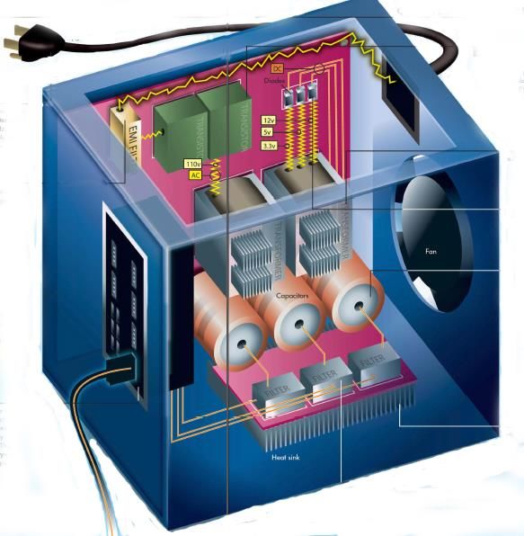
Higher Cert/Bachelor of Technology – DT036A
                                                       Computer Systems
     Computer Hardware – Hardware Components & Internal PC Connections:

You might see a specification for a PC 1 such as "containing an Intel i7 Hexa core
processor - 3.46GHz, 3200MHz Bus, 384 KB L1 cache, 1.5MB L2 cache, 12 MB L3
cache, 32nm process technology; 4 gigabytes of RAM, ATX motherboard, Windows 7
Home Premium 64-bit operating system, an Intel® GMA HD graphics card, a 500
gigabytes SATA hard drive (5400rpm), and WiFi 802.11 bgn". This section aims to
discuss a selection of hardware parts, outline common metrics and specifications used
to describe them, what they measure as well as their operation.

POWER SUPPLY: ................................................................................................................................. 2
HEAT SINKS/FANS: ............................................................................................................................. 3
CASE: ................................................................................................................................................. 5
MANUFACTURERS: ASUS, FOXCONN MOTHERBOARD: .................................................................... 5
MOTHERBOARD: ................................................................................................................................ 6
EXPANSION CARDS: ........................................................................................................................... 9
RAM MEMORY: ................................................................................................................................ 11
CACHE MEMORY: ............................................................................................................................. 13
REGISTERS:....................................................................................................................................... 15
BIOS: ................................................................................................................................................ 15
BOOT-UP PROCESS: .......................................................................................................................... 16
CHIPSET: .......................................................................................................................................... 17
PCI BUS: ........................................................................................................................................... 19
AGP BUS: ......................................................................................................................................... 20
PCI EXPRESS 1.0 BUS: ....................................................................................................................... 20
(IDE) ATA INTERFACE: ...................................................................................................................... 22
SERIAL ATA (SATA): .......................................................................................................................... 23

1
    http://www.tomshardware.com

jerome.casey@dit.ie                                                                                                                                   1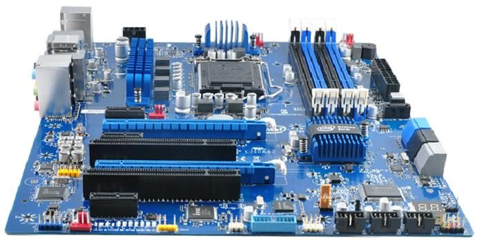
Power Supply:
The power supply converts the alternating current (AC) from your mains (110V
input or 220V input) to the direct current (DC) needed by the computer 2. In a PC,
the power supply is the metal box usually found in a corner of the case. The power
supply is visible from the back of many systems because it contains the power-cord
receptacle and the cooling fan. Power supplies - often referred to as switching power
supplies, use switcher technology to convert the AC input to lower DC voltages. The
typical voltages produced are:    •3.3 volts, •5 volts, •12 volts

Figures: left: A Typical ATX 1.3 power supply. From left to right, the connectors are 20-pin motherboard 3, 4-pin
"P4 connector", fan RPM monitor (note the lack of a power wire), SATA power connector (black), "Molex
connector", and floppy connector; middle and right: shows the power supply with three small transformers
(yellow) in the center. To the left are two cylindrical capacitors. The large finned pieces of aluminum are heat
sinks. The left heat sink has transistors attached to it. These are the transistors in charge of doing the switching --
they provide high-frequency power to the transformers. Attached to the right heat sink are diodes that rectify AC
signals and turn them into DC signals.

Figure: A power supply schematic showing the AC input, fan, EMI filter (yellow), transformers, cylindrical
capacitors, filters, aluminum heat sink, rectifying diodes, and 3 outgoing DC voltage lines. (White, 2008)

The 3.3-volts and 5-volts are typically used by digital circuits, while the 12-volt is
used to power fans and motors in disk drives. The main specification of a power
supply is in watts. A watt is the product of the voltage in volts and the current in
amperes or amps.

2
    In a laptop the conversion is done by the AC adapter in the power cable.
3
    In current ATX this has changed from 20 pin to 24 pin (2 x12) to support PCI-Express* requirements

jerome.casey@dit.ie                                                                                                  2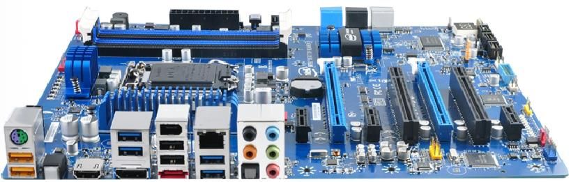
The form factor of the power supply refers to its general shape and dimensions. The
form factor of the power supply must match that of the case that it is supposed to go
into, and the motherboard it is to power.

Power Supply Wattage:
A 400-watt switching power supply will not necessarily use more power than a 250-
watt supply. A larger supply may be needed if you use every available slot on the
motherboard or every available drive bay in the personal computer case. It is not a
good idea to have a 250-watt supply if you have 250 watts total in devices, since the
supply should not be loaded to 100 percent of its capacity.

According to PC Power & Cooling, Inc., some power consumption values (in watts)
for common items in a personal computer are:

Component                      Requirement
AGP Video Card                 30W - 50W
PCI Express Video              100W - 250W
                                                       If you use a PSU that does not supply
Average PCI Card               5W - 10W
                                                       enough power for the system, any of
DVD/CD                         20W - 30W               the following symptoms might occur:
Hard Drive                     15W - 30W
                                                       (i) System does not boot,
                                                       (ii) System randomly shuts down,
Case/CPU Fans                  3W (ea.)                (iii) Add-in devices do not work
Motherboard (w/o CPU or RAM)   50W - 150W              properly. Intel (2014a)
RAM                            15W per 1GB
Processor                      80W - 140W

For overall power supply wattage, add the requirement for each device in your
system, then multiply by 1.5. The multiplier takes into account that today’s systems
draw disproportionally on the +12V output. Furthermore, power supplies are more
efficient and reliable when loaded to 30% - 70% of maximum capacity.
Source: http://www.pcpower.com/technology/power_usage

Heat Sinks/Fans:
As processors, graphics cards, RAM and other components in computers have
increased in speed and power consumption, the amount of heat produced by these
components as a side-effect of normal operation has also increased. These
components need to be kept within a specified temperature range to prevent
overheating, instability, malfunction and damage leading to a shortened component
lifespan. Other devices which need to be cooled include the power supply unit,
optoelectronic devices such as higher-power lasers and light emitting diodes (LEDs)
and hard disks.
        A heat sink is a heat exchanger component attached to a device used for
passive cooling. It is designed to increase the surface area in contact with the cooling
fluid surrounding it, such as the air thus allowing it to remove more heat per unit time.
Other factors which improve the thermal performance of a heat sink are the approach
air velocity, choice of material – usually an aluminum alloy due to its high thermal
conductivity values (229 W/mºK), fin (or other protrusion) design and surface
treatment.

jerome.casey@dit.ie                                                                            3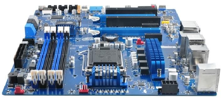
Figures: Above A fan-cooled heat sink on the processor of a PC. To the right of it is a smaller heat sink cooling
another integrated circuit of the motherboard. Below 3 types of Heat-sink design: Pin, Straight (running the entire
length of the heat sink), Flared.

        The approach air velocity depends on the attached or nearby fan. When there
is no air flow around the heat sink, energy cannot be transferred. A computer fan is
any fan inside, or attached to, a computer case used for active cooling, and may refer
to fans that draw cooler air into the case from the outside, expel warm air from inside,
or move air across a heat sink to cool a particular component.

jerome.casey@dit.ie                                                                                              4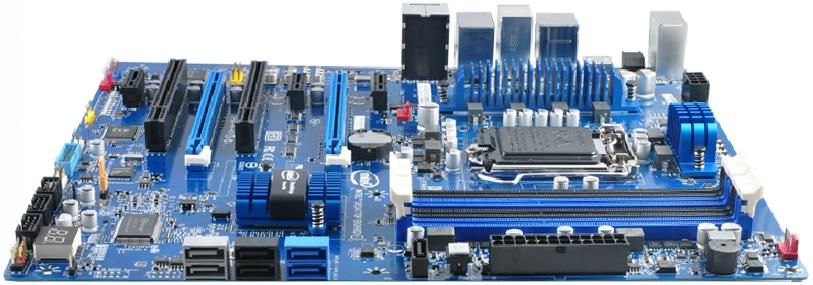
Case:
A computer case (also known as a computer chassis, cabinet, box, tower, enclosure,
housing, system unit or simply case) is the enclosure that contains most of the
components of a computer (usually excluding the display, keyboard and mouse). If
you are building your own computer selecting the case will be one of your first
choices to make: the type of case, its size, orientation, the number of bays you will
need etc.

Figure: shows a stripped ATX desktop case. The motherboard will lie flat on the bottom, against the right panel,
with peripheral connectors protruding through the rear panel, drive bays at the top and front, and the power supply
at the top and rear.

Sizes
Cases can come in many different sizes (known as form factors). The size and shape
of a computer case is usually determined by the form factor of the motherboard, since
it is the largest component of most computers. Consequently, personal computer form
factors typically specify only the internal dimensions and layout of the case.
         For example, a case designed for an ATX motherboard and power supply may
take on several external forms, such as a vertical tower (designed to sit on the floor,
height > width) or a flat desktop (height < width) or pizza box (height ≤ 2 inches,
designed to sit on the desk under the computer's monitor). Full-size tower cases are
typically larger in volume than desktop cases, with more room for drive bays and
expansion slots. Desktop cases—and mini-tower cases designed for the reduced
microATX form factor—are popular in business environments where space is at a
premium.

Major Component Locations:
1. The motherboard is usually screwed to the case along its largest face, which could
   be the bottom or the side of the case depending on the form factor and orientation.
2. Form factors such as ATX provide a back panel with cut-out holes to expose I/O
   ports provided by integrated peripherals, as well as expansion slots which may
   optionally expose additional ports provided by expansion cards.
3. The power supply unit is often housed at the top rear of the case; it is usually
   attached with four screws to support its weight.
4. Most cases include drive bays on the front of the case; a typical ATX case includes
   a 5.25" bay (used mainly for optical drives) and 3.5" bays used for hard drives,
   floppy drives, and card readers.
5. Buttons and LEDs are typically located on the front of the case; some cases include
   additional I/O ports, temperature and/or processor speed monitors in the same area.
6. Vents are often found on the front, back, and sometimes on the side of the case to
   allow cooling fans to be mounted via surrounding threaded screw holes.

Manufacturers: Asus, Foxconn

jerome.casey@dit.ie                                                                                              5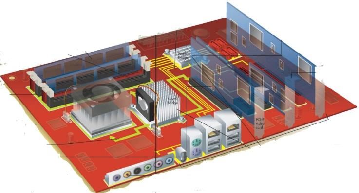
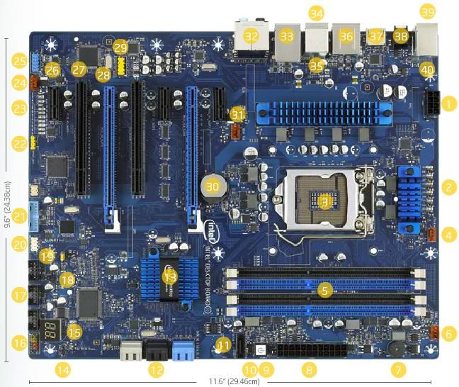
Motherboard:
The motherboard is the key circuit board holding the essential processing parts of a
computer. It allows all the parts of your computer to receive power and
communicate with one another. It is usually screwed to the case along its largest
face, which could be the bottom or the side of the case depending on the form factor
and orientation. The form factor describes the shape and layout of the motherboard.
It affects where individual components go and the shape of the computer's case.
Attached directly to the motherboard are the CPU, RAM, expansion cards,
networking, video, and audio components.

Figures: Above: An older motherboard, Below: the Intel Z77 motherboard.

ATX (Advanced Technology eXtended) is a motherboard form factor specification
developed by Intel in 1995. A full-size ATX board is 12 × 9.6 in (305 × 244 mm). It
was the first big change in computer case, motherboard, and power supply design in
many years, improving standardization and interchangeability of parts. The
specification defines the key mechanical dimensions, mounting point, I/O panel,
power and connector interfaces between a computer case, a motherboard, and a power
supply. The specification has been revised numerous times since 1995, the most
recent being version 2.3, released in 2007.

Standards: ATX, standards for smaller boards: microATX, FlexATX and mini-ITX.

jerome.casey@dit.ie                                                               6
27     26    28     26

                                                                     41

                                                                                               41

                      Figure: the Intel Z77 motherboard (Plan View). (Intel, 2014b)

 1. 12V Processor Core Voltage             15. POST Code LED Display                  29. High Definition (HD)
 Connector (8 pin)                                                                    Audio AC97 Front Panel
                                                                                      Header
2. Voltage Regulator status LEDs           16. Front Panel Header                     30. CMOS RAM Battery
3. Processor Socket (LGA1155)              17. USB 2.0 Dual-Port Header               31. Rear Chassis Fan Header
                                           (black)                                    (4 pin)
4. Processor Fan Header (4 pin)            18. Chassis Intrusion Header               32. 5 port audio with S/PDIF
5. Memory Slots                            19. BIOS Configuration Jumper              33. Intel Gigabit (10/100/1000
                                                                                      Mb/s) Ethernet LAN
6. Front Chassis Fan Header (4 pin)        20. Consumer IR (CIR) headers              34. IEEE 1394a port
7. Onboard Speaker                         21. USB 3.0 Front Panel Connector          35. External Serial ATA
                                           (blue)                                     (eSATA) port (3 Gb/s)
8. Main Power Connector                    22. S/PDIF out Header (4 pin)              36. USB ports:
(2x12 pin)                                                                            4 USB 3.0 ports (blue)
                                                                                      2 USB 2.0 ports (black)
9. Onboard Power Button                    23. Diagnostic Status LEDs                 37. Graphics ports
10. +5V Standby Power Indicator LED        24. Auxiliary chassis fan header           38. Back to BIOS button
                                            (4 pin)
11. SATA 3.0 Connector (black)             25. IEEE 1394a front panel header          39. PS/2 port
12. SATA Ports:                            26. PCI Express 2.0 x1 connector           40. USB 2.0 ports (yellow)
(4 SATA 6.0 ports (blue & grey)                                                       2 high current/ fast charging
(2 SATA 3.0 ports (black)                                                             ports
13. Intel z77 Express Chipset              27.   Conventional     PCI    bus          41. Voltage Regulator modules
                                           connector                                  with heat sinks
14. Alternate Front Panel Power LED        28. PCI Express 3.0 x16 connector
Header

jerome.casey@dit.ie                                                                                       7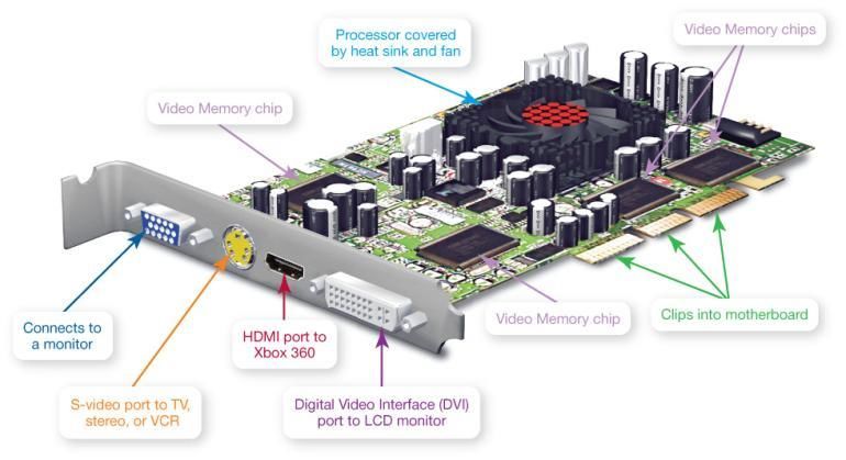
Figure: the Intel Z77 Motherboard (North View).

                      Figure: the Intel Z77 Motherboard (South View).

                      Figure: the Intel Z77 Motherboard (West View).

                      Figure: the Intel Z77 Motherboard (East View).

jerome.casey@dit.ie                                                     8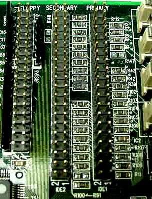
Expansion Cards:
Special expansion cards are one way to add new types of ports to an older computer
or to expand the number of ports on your computer. Like other expansion cards, these
cards clip into an open expansion slot on the motherboard.

                       Figure: An expansion card with 3 USB ports and 2 Firewire ports.

Video (Graphics) Card:
A dedicated video card (or video adapter) is an expansion card installed inside your
system unit to translate binary data received from the CPU or GPU into the images you
view on your monitor. It is an alternative to the integrated graphics chip.
Modern video cards include ports allowing you to connect to different video equipment;
also they contain their own RAM, called video memory.
Video cards also come with their own processors or GPUs. Calls to the CPU for graphics
processing are redirected to the processor on the video card, significantly speeding up
graphics processing. Updating to a dedicated graphics card offloads work from the CPU
and system RAM, so not only will graphics processing be faster, but the system’s overall
performance will improve.
The video card also controls the number of colors your monitor can display. The number
of bits the video card uses to represent each pixel on the monitor (referred to as the bit
depth) determines the color quality of the image displayed. The more bits available, the
better the color detail of the image.

Figure: A Graphics card with output ports for both digital and analog video. The GPU sits under the fan (red) and
heatsink.

jerome.casey@dit.ie                                                                                            9
Figure: A mid-range video card optimized for dual-GPU gaming (NVIDIA SLI)
Manufacturers: Nvidia (GeForce 4), AMD (Radeon).
Sound Card
Figure: Left An older sound card expansion card. Right Sound card module as an integrated circuit on the Z77
motherboard. Indicator is showing the RealTek audio chip. In the bottom right you see the front panel audio
connector which would be plugged into the microphone jack and headphone jack on the front of the case.
Sound cards attached to the motherboard and enabled your computer to record
and reproduce sounds.
Most computers ship with a basic sound card, most often a 3D sound card. 3D
sound is better than stereo sound at convincing the human ear that sound is
omnidirectional, meaning that you can’t tell what direction the sound is
coming from. This tends to produce a fuller, richer sound than stereo sound.
To set up surround sound on your computer, you need two things: a set of
surround-sound speakers and a sound card that is Dolby Digital compatible.
There are many formats to choose from such as Dolby Digital EX, Dolby
Digital Plus, and Dolby TrueHD.
The ports on the sound card allow you to connect additional audio devices such as
amplified speakers, headphones, microphones etc.
4
The technology demos from Nvidia used to showcase the rendering power of the chip. See YouTube
and http://www.nvidia.com/coolstuff/demos
jerome.casey@dit.ie 10Network Card:
Figure: Left An older Network card expansion card. Right The Gigabit Ethernet Card as a integrated circuit on
the Z77 motherboard. The indicator is pointing to the Gigabit Ethernet chip, while just below it is a crystal.
An Ethernet network requires that you install or attach network adapters to each
computer or peripheral you want to connect to the network. Most computers come
with Ethernet adapters preinstalled as network interface cards (NICs).
If your computer doesn’t have a NIC, your options are: (i) buy one and install it, or
(ii) use a USB adapter, which you plug into any open USB port on the system unit.
RAM Memory:
Random access memory (RAM) is a series of small cards or modules plugged into
slots on the motherboard. The CPU can request any data in RAM. It is then located,
opened, and delivered to the CPU for processing in a few billionths of a second. Since
all the contents of RAM are erased when you turn off the computer, RAM is the
temporary or volatile storage location for the computer.
Figure: A RAM Memory Module.
Operation:
Similar to a microprocessor, a memory chip is an integrated circuit (IC) made of
millions of transistors and capacitors. In the most common form of computer
memory, dynamic random access memory (DRAM), a transistor and a capacitor are
paired to create a memory cell, which represents a single bit of data. The capacitor
holds the bit of information - a 0 or a 1. The transistor acts as a switch that lets the
control circuitry on the memory chip read the capacitor or change its state.
A capacitor is like a small bucket that is able to store electrons. To store a 1 in the
memory cell, the bucket is filled with electrons. To store a 0, it is emptied. The
problem with the capacitor's bucket is that it has a leak. In a matter of a few
milliseconds a full bucket becomes empty. Therefore, for dynamic memory to work,
either the CPU or the memory controller has to come along and recharge all of the
capacitors holding a 1 before they discharge. The capacitors must to be energized
every 15ms or so (hundreds of times per second) to maintain their charge. To do this,
the memory controller reads the memory and then writes it right back. This is
refresh operation happens automatically and is how dynamic RAM got its name.
Dynamic RAM has to be dynamically refreshed all of the time or it forgets what it is
holding. The downside of all of this refreshing compared to SRAM is that it takes
time and slows down the memory.
jerome.casey@dit.ie 11Figure: (a) Empty Memory Cells (a 0), (b) voltage applied to Column and Row lines (c) 4 cells charged
Memory cells are etched onto a silicon wafer in an array of columns (bitlines) and
rows (wordlines). The intersection of a bitline and a wordline constitutes the address
of the memory cell.
DRAM works by sending a charge (an electrical signal called a strobe) through the
appropriate column (CAS) to activate the transistor at each bit in the column. When
writing, the row lines contain the state the capacitor should take on. When reading,
the sense-amplifier determines the level of charge in the capacitor. If it is more than
50 percent, it reads it as a 1; otherwise it reads it as a 0. The counter tracks the refresh
sequence based on which rows have been accessed in what order. The length of time
necessary to do all this is so short that it is expressed in nanoseconds (billionths of a
second). A memory chip rating of 70ns means that it takes 70 nanoseconds to
completely read and recharge each cell.
Memory cells alone would be worthless without some way to get information in and
out of them. So the memory cells have a whole support infrastructure of other
specialized circuits. These circuits perform functions such as:
•Identifying each row and column (row address select and column address select)
•Keeping track of the refresh sequence (counter)
•Reading and restoring the signal from a cell (sense amplifier)
•Telling a cell whether it should take a charge or not (write enable)
Other functions of the memory controller include a series of tasks that include
identifying the type, speed and amount of memory and checking for errors.
1. When you open an application such as Excel, it is loaded into RAM. To conserve
RAM usage, many applications load only the essential parts of the program
initially and then load other pieces as needed.
2. After an application is loaded, any files that are opened for use in that application
are loaded into RAM.
3. When you save a file and close the application, the file is written to the specified
storage device, and then it and the application are purged from RAM.
jerome.casey@dit.ie 12How Much RAM do you need?
The amount of RAM actually sitting on memory modules in your computer is your
computer’s physical memory. The memory that your operating system uses is
referred to as kernel memory. To determine how much RAM your computer needs,
look at the memory requirements for each program and add them up.
• You need RAM for the operating system, application software, and data. If your
system responds slowly or accesses the hard drive constantly, then you need to
add more RAM
Table: Sample RAM requirements:
Application Minimum RAM Required
Windows 7 1000 MB
Microsoft Office Professional 2007 256 MB
Internet Explorer 8 128 MB
iTunes 256 MB
Adobe Photoshop Elements 512 MB
Total RAM required to run all programs
simultaneously 2,152 MB or 2.15 GB
To save data more permanently, you need to save it to the hard drive or to another
permanent storage device such as a CD or flash drive.
Read-only memory (ROM) holds all the instructions the computer needs when it is
powered on. The data does not get erased when the power is turned off.
Metrics for RAM speed:
System RAM speed is controlled by bus width and bus speed. Bus width refers to the
number of bits that can be sent to the CPU simultaneously, and bus speed refers to
the number of times a group of bits can be sent each second. A bus cycle occurs every
time data travels from memory to the CPU. For example, a 100-MHz 32-bit bus is
theoretically capable of sending 4 bytes of data to the CPU 100 million times per
second, while a 66-MHz 16-bit bus can send 2 bytes of data 66 million times per
second. If you do the sums, you’ll find that simply changing the bus width from 16
bits to 32 bits and the speed from 66 MHz to 100 MHz in our example allows for
three times as much data (400 million bytes versus 132 million bytes) to pass through
to the CPU every second for processing.
Cache Memory:
Even with a wide and fast bus, it still takes longer for data to get from the memory
card to the CPU than it takes for the CPU to actually process the data. Caches are
designed to alleviate this bottleneck by making the data that is used most often by the
CPU instantly available. This is accomplished by building a small amount of memory,
known as primary or level 1 cache, right into the CPU. Level 1 cache is very small,
e.g. 384 KB L1 cache for the Intel i7 Hexa core.
The secondary or level 2 cache typically resided on a memory card located near the
CPU with a direct connection to the CPU. A dedicated integrated circuit on the
motherboard, the L2 controller, regulates the use of the level 2 cache by the CPU.
e.g. 1.5 MB L2 cache for the Intel i7 Hexa core. In most systems, data needed by the
CPU is accessed from the cache approximately 95 percent of the time, greatly
reducing the overhead needed when the CPU has to wait for data from the main
memory.
jerome.casey@dit.ie 13Some inexpensive systems dispense with the level 2 cache altogether. Many high
performance CPUs now have the level 2 cache actually built into the CPU chip itself
as well as a level 3 cache. Therefore, the size of the level 2 cache and whether it is
onboard (on the CPU) is a major determining factor in the performance of a CPU.
e.g. 12 MB L3 cache for the Intel i7 Hexa core.
& Level 3
Figure: CPU Memory Access Hierarchy Chart. Level 3 cache is now common.
How Caching Operates:
A particular type of RAM, static random access memory (SRAM), is used primarily
for cache. SRAM uses multiple transistors, typically four to six, for each memory cell.
It has an external gate array known as a bistable multivibrator that switches, or flip-
flops, between two states. This means that it does not have to be continually refreshed
like DRAM. Each cell will maintain its data as long as it has power. This means
SRAM can operate extremely quickly, significantly faster than dynamic RAM.
However the complexity of each cell means it takes up a lot more space on a chip and
makes it prohibitively expensive for use as standard RAM.
Static RAM is fast and expensive, and dynamic RAM is less expensive and slower.
Thus static RAM is used to create the CPU's speed-sensitive cache, while dynamic
RAM forms the larger system RAM space.
Some principles of cache operation are as follows:
1. Cache technology is the use of a faster but smaller memory type to accelerate a
slower but larger memory type, such as RAM.
2. When using a cache, you must check the cache to see if an item is in there. If it is
there, it’s called a cache hit. If not, it is called a cache miss and the computer must
wait for a round trip from the larger, slower main memory area.
3. A cache has some maximum size that is much smaller than the larger main
memory storage area.
4. It is possible to have multiple cache layers. In a one-level cache, the Level 1
cache is first checked, if there is a miss, the RAM is searched. In a two-level cache
the Level 1 cache is first checked, if there is a miss, the Level 2 cache is checked,
if there is a miss, the RAM is searched.
5. Cache is populated using a concept called locality of reference. It means that in a
fairly large program, only small portions are ever used at any one time. Even if an
executable is 10 MB in size, only a handful of bytes from that program are in use
at any one time, and their rate of repetition is very high.
jerome.casey@dit.ie 14Registers:
The final step in memory hierarchy are the registers. These are memory cells built
right into the CPU that contain specific data needed by the CPU, particularly the
arithmetic and logic unit (ALU). An integral part of the CPU itself, they are
controlled directly by the compiler that sends information for the CPU to process.
BIOS:
The basic input-output system (BIOS) is the first thing you see when you turn on
your computer. The BIOS is special software that interfaces the major hardware
components of your computer with the operating system. It is usually stored on a
Flash memory chip on the motherboard (which has its own battery), but sometimes
the chip is another type of ROM.
Figure: The BIOS chip and the BIOS setup Utility program
The BIOS software has a number of different roles, but its most important role is to
load the operating system. When you turn on your computer and the microprocessor
tries to execute its first instruction, it has to get that instruction from somewhere. It
cannot get it from the operating system because the operating system is located on a
hard disk, and the microprocessor cannot get to it without some instructions that tell it
how. The BIOS provides those instructions. Some of the other common tasks that the
BIOS performs includes:
1. A power-on self-test (POST) for all of the different hardware components in the
system to make sure everything is working properly.
2. Activating other BIOS chips on different cards installed in the computer – e.g.
SCSI and graphics cards often have their own BIOS chips.
3. Providing a set of low-level routines that the operating system uses to interface to
different hardware devices - it is these routines that give the BIOS its name. They
manage things like the keyboard, the screen, and the serial and parallel ports,
especially when the computer is booting.
4. Managing a collection of settings for the hard disks, clock, etc.
Manufacturers: American MegaTrends Inc. (AMI), Phoenix Technologies, Ali,
Winbond.
e.g. say you insert more RAM memory once the module is installed, close the case,
plug the computer back in and power it up. When the computer starts the POST, it
should automatically recognize the memory.
jerome.casey@dit.ie 15Boot-Up Process:
A PC cannot do anything useful unless it is running its operating system - software
that acts as a supervisor for all its software applications. It sets the rules for using
memory, drives, and other hardware devices on the computer. Before a PC can run the
operating system, it needs some way to load it from disk into RAM. The way to do
this is with the bootstrap – a small amount of code that is executed on startup or
system boot. The bootstrap is aptly named because it lets the PC do something
entirely on its own 5, without any outside operating system. The boot-up sequence of
events is as follows:
1. The computer loads the basic input/output system (BIOS) from ROM. The
BIOS provides the most basic information about storage devices, boot sequence,
security, Plug and Play (auto device recognition) capability and a few other items.
2. The BIOS triggers a test called a power-on self-test (POST) to make sure all the
major components are functioning properly. You may hear your drives spin and
see some LEDs flash, but the screen, at first, remains black.
3. The BIOS has the CPU send signals over the system bus to be sure all of the
basic components are functioning. The bus includes the electrical circuits printed
on and into the motherboard, connecting all the components with each other.
4. The POST tests the memory contained on the display adapter and the video
signals that control the display. This is the first point you’ll see something appear
on your PC’s monitor.
5. During a cold boot the memory controller checks all of the memory addresses
with a quick read/write operation to ensure that there are no errors in the memory
chips. Read/write means that data is written to a bit and then read back from that
bit. You should see some output to your screen - on some PCs you may see a
running account of the amount of memory being checked.
6. The computer loads the operating system (OS) from the hard drive into the
system’s RAM. That ends the POST and the BIOS transfers control to the
operating system. Generally, the critical parts of the operating system - the kernel
- are maintained in RAM as long as the computer is on. This allows the CPU to
have immediate access to the operating system, which enhances the performance
and functionality of the overall system.
See more on POST Codes Ranges, the operation that corresponds to the code and the
POST sequence at http://www.intel.com/support/motherboards/desktop/sb/CS-025434.htm
5
The origin of the word “boot up” comes from the concept of lifting yourself up by your bootstraps.
jerome.casey@dit.ie 16Chipset:
The PC has become so complex that even the most recent, powerful processors can’t
do the entire job of managing the flow of data by themselves. The CPU has been
given help in the form of the chip set, located nearby on the motherboard. The chip
set traditionally consisted of two microchips, often referred to as the North Bridge
and the South Bridge, that acted as the administrators to the CPU, or chief executive.
The chip set bridged logical and physical gaps between the CPU and other chips, all
the time watching and controlling the input and output of specific components. The
exact function of the chip set is constantly changing.
In 2003 AMD introduced the AMD Athlon 64 bit chip, where the CPU reclaimed
some of the memory controller functions of the North Bridge. Intel later also adopted
this architecture with their core i-series of processors.
But in all cases, the bridges determine what kinds of memory, processors, and other
components can work with that particular motherboard. There is now a trend to
replace the names North Bridge and South Bridge with less elegant terms such as
Graphics Memory Controller Hub (GMCH) and the I/O Controller Hub (ICH),
even though their basic purpose is the same.
Where a motherboard still has the older architecture
you can distinguish the North Bridge because it
resides as close as possible to three other components
that are connected to this chip: the CPU, the
memory, and the graphics port. Even though
connections are at the speed of light, their proximity
on the motherboard does make a difference. When
you’re counting in nanoseconds (billionths of a
second) ‘small differences’ are significant. When the
CPU needs data from RAM, it sends a request to the
North Bridge memory controller6. The controller, in
turn, sends the request along to memory and tells the
CPU how long the processor must wait to read the
memory over a speedy connection called the front
side bus (FSB). The remaining connection of the
North Bridge is to the South Bridge.
The South Bridge primarily handles the
routing of traffic between the various input/output
(I/O) devices on the system for which speed is not
vital to the total performance, such as the disk drives Figure: A Block Diagram showing the Bus
Systems between components on the
(including RAID drive arrays), optical drives, PCI- Motherboard.
Express devices, the older PCI bus, and the USB, Ethernet, and audio ports. It is also
responsible for less prominent input/output, such as the real-time clock, interrupt
controller, and power management. The remaining slowcoaches of the computer - the
keyboard, the serial ports, and the mouse - are handled by a separate device called the
SIO or super input/ output.
6
The memory controller also constantly renews the memory modules (RAM). Since the charge begins to dissipate as soon as it's created, the
bridge's memory controller endlessly, thousands of times a second, reads each of the millions of cells and writes back the values it read.
jerome.casey@dit.ie 17Figure: the Motherboard with the North Bridge and South Bridge highlighted on an older motherboard
Figure: the Z77 Motherboard – the i-series CPU has made the NorthBridge chip obsolete.
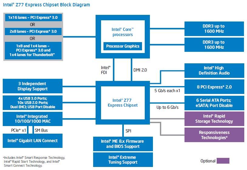
Figure: Intel z77 Express Chipset Block Diagram
jerome.casey@dit.ie 18PCI Bus:
The Peripheral Component Interconnect (PCI) bus produced by Intel in 1992
provided direct access to system memory for any connected hardware devices.
Figure: PCI slots on a motherboard.
This bus allowed multiple packets of information from different sources to travel
down it simultaneously. Previously it was used to connect to the graphics card and
this setup meant that information from the graphics card travelled through the bus
along with any other information coming from a device connected to the PCI. When
all the information arrived at the CPU, it had to wait in line to get time with the CPU.
This system worked well for many years, but eventually the PCI bus could not keep
up. The Internet and most software were more and more graphically oriented, and the
demands of the graphics card needed priority over all other PCI devices.
This is now a legacy technology and is used for functions that do not require great
quantities or speed in data transmissions. PCI slots were mainly used for network,
graphics and sound cards.
Figure: PCI card showing the pins (4+2+24+10+8+2) and PCI bridge chip.
PCI cards use 47 pins to attach to a PCI slot. Pins are thin metal feet that allow
computer chips to be attached to a circuit board. AGP replaced the PCI as the standard
way to connect a graphics card to the motherboard.
jerome.casey@dit.ie 19AGP Bus:
In 1996, Intel introduced AGP as a more efficient way to deliver streaming video and
real-time-rendered 3-D graphics that were becoming more prevalent in all aspects of
computing to and from the CPU. Previously, the standard method of delivery was the
PCI bus.
Figure: an AGB based graphics card.
AGP is based on the design of the PCI bus; but unlike a bus, it provides a dedicated
point-to-point connection from the graphics card to the CPU. With a clear path to
the CPU and system memory, AGP provided a much faster, more efficient way for a
computer to get the information it needed to render complex graphics.
An AGP, or accelerated graphics port, allowed the operating system to designate
RAM for use by the graphics card on the fly.
AGP started with a bandwidth of 266 MB/s; AGP 2x -> 533 MB/s;
AGP 4x -> 1066 MB/s; AGP 8x -> 2133 MB/s. However, AGP then became
overtaken by the newer PCI-Express slots, which come in several denominations to
make them the do-all, fit-all slot for every expansion board, not just graphics.
PCI Express 1.0 Bus:
PCI Express or PCIe began to appear in 2004 and eliminates the need for the AGP by
accepting more data and supplying more power to video cards. By early 2006, most
motherboards featured PCI x16 slots (4,000MB/s) in place of AGP 8x.
The shorter ones (shown below) are xl PCIe slots and are common to all PCI Express
slots. PCI-Express slots will also accept older PCI cards. To handle graphics and
sound data faster, the PCIe slot can be expanded to x2, x4, x8, or, x16 slots, where the
numbers represent multiples of the speed of an xl PCIe slot. Their ability to move data
is indicated by the multiplier factor in their designations.
New computer applications, such as streaming video and photo editing, put new
demands on PCs to move vast amounts of data ever quicker. Even the fastest of them,
AGP 8x, which spewed out 2.133 GB/s, was not good enough for the demands of
real-time-photorealistic animation that needs values for the colors of millions of
pixels pushed through the circuits 60 times or more each second. The solution is a bus
architecture that uses both parallel and serial transfers.
jerome.casey@dit.ie 20Operation:
A PCI-Express bus breaks all data (payload) it handles into pieces and wraps the
pieces in a packet. The packet includes other binary codes that identify where the
information has come from, its destination, its sequence among all the other packets
being sent, and the results of a cyclic redundancy check (CRC). A CRC is a
mathematical operation that detects transmission errors in the data. 7
e.g. 8b/10b means 8 bits of data transferred for every 10 bits sent
Figure: A Packet and its constituents: Frame Number, CRC, Data (Payload), Header, Footer.
After subtracting the overhead for packet packaging, the basic PCI-Express x1 slot
has a top bandwidth of 250 Megabytes a second (MB/s). But PCI-E is scalable.
Devoting two or more lanes to send data to and from a single component - called
channel bonding - increases the bandwidth for each lane added to the channel. PCI-E
transfers data at 250 MB/s in each direction per lane. A lane is composed of two
differential signalling pairs: one pair for receiving data, the other for transmitting.
Thus, each lane is composed of four wires or signal traces.
With a maximum of 32 lanes, PCI-E 1.0 allows for a total combined transfer rate
of 8 GB/s in each direction. That gives a single channel nearly twice the bandwidth
of the older PCI and an eight lane slot a data rate comparable to the fastest version of
AGP. You can identify the expansion slots with the increased bandwidth by
comparing the slots’ lengths. The basic PCIe x1 slot is about 24.5mm long. Each
13.5mm added to other slots represents another 250MB added to their bandwidth.
Figure: PCI express x1, x4, x8 and x16 connector slots. x4 and x8 appear mainly in servers.
7
Checksum (summation check) – a technique for determining whether a package of data is valid. The package, a
string of binary digits, is added up and compared with the expected number.
jerome.casey@dit.ie 211. The chipset sends packets serially over two lines. Another pair of lines is responsible for packets going in the opposite directions. Taken together, the two pairs are called a lane. One of the lines in each pair carries the original signal. The other line carries a negative image of the signal; each 0 becomes a 1 and each 1 becomes a 0 (differential signalling). The lines are laid out so that any electrical noise, or static, that affects one line should also affect the other. 2. When packets reach their destination, the receiver restores the negative packet to its positive version. That same operation reverses the values of any junk signals introduced by electrical interference. The bus combines the two paired packets, and any interference in the original packet is cancelled by its negative image in the matching packet. 3. It also performs the same CRC operation that was performed on the packet before its journey and compares its result to the earlier one bundled into the packet. If CRCs differ, the bus orders the packet be re-sent. Since the sequence of the data in each packet is included in the packet, the bus doesn't have to wait for the corrected packet. It can continue to accept other packets and then put them all back in the correct order when all the packets have been received. PCI Express Bandwidth * Bandwidth ǂ Encoding Year Released Version 1.0 250MB/s (2 GB/s) 8b/10b 2002 2.0 500MB/s (4 GB/s) 8b/10b 2007 3.0 1000MB/s (~ 8 GB/s) 128b/130b 2010 * Per lane, in each direction ǂ Per 8 lanes, in each direction (IDE) ATA Interface: Usually, these devices connect to the computer through an Integrated Drive Electronics (IDE) interface. Essentially, an IDE interface is a standard way for a storage device to connect to a computer. IDE is actually not the true technical name for the interface standard. The original name, AT Attachment (ATA) or parallel ATA, signified that the interface was initially developed for the IBM AT computer. We will learn about the evolution of IDE/ATA, what the pinouts are and exactly what “slave” and “master” mean in IDE. Figure: Left A close-up of the primary and secondary IDE interfaces on a motherboard; Right The connector on an IDE cable, the stripe denotes where to align with Pin 1. IDE quoted upper transfer rates of 133MB/s. Above that, crosstalk, or electrical interference, from their 40-wire parallel cables drowns out meaningful communication. jerome.casey@dit.ie 22
Serial ATA (SATA):
Serial ATA was designed to replace the older parallel ATA (PATA) standard (often
called by the old name IDE), offering several advantages over the older interface:
1. reduced cable size (7 conductors compared to 40 with the wider PATA ribbon
   cable) – which facilitates a more efficient airflow inside a form factor and also
   allows for smaller chassis designs as well as a reduced cost,
2. native hot swapping,
3. faster data transfer through higher signalling rates, and
4. more efficient transfer through an (optional) I/O queuing protocol.

The SATA standard defines a data cable with seven conductors (3 grounds and 4
active data lines in two pairs of conductors) and 8 mm wide wafer connectors on each
end. The three grounding wires dampen any crosstalk. A SATA cable can have a
length up to 1 metre (3.3 ft), and connects one motherboard socket to one hard drive.

    SATA revision     Bandwidth (Coded)     Bandwidth (Actual)       Year
    1.0               1.5 Gbit/s            1.2 Gbit/s (150MB/s) *   2003
    2.0               3 Gbit/s              2.4 Gbit/s (300MB/s) *   2005
    3.0               6 Gbit/s              4.8 Gbit/s (600MB/s) *   2009

* 8b/10b encoding

Figure: Left The 7-Pin SATA data cable (angled end); Middle The SATA data cable (angled and
straight ends); Right The SATA connectors on the motherboard (straight);
Below Left The SATA Data connector Pinout; Below Right The SATA connector on a hard drive (7
pin data connector on the left and 15 pin power connector on the right). Pins are spaced 1.27mm apart.

jerome.casey@dit.ie                                                                                23
References: 1. Asus (2014) Thermal Armor Total Airflow-Boosting Circulation Test http://www.asus.com/Motherboards/SABERTOOTH_Z77 2. Eastaugh, Matthew, (2004) Micro processor Tutorial: http://www.eastaughs.fsnet.co.uk/cpu/structure-reg.htm 3. HowStuffWorks (2014) A useful site for various computer articles, images and video. http://computer.howstuffworks.com 4. Intel (2014a) Desktop Boards Power supply considerations for building a computer, http://www.intel.com/support/motherboards/desktop/sb/CS-008646.htm 5. Intel (2014b) Intel® Desktop Board DZ77BH Interactive Layout http://www.intel.com/content/www/us/en/desktops/desktop-board-dz77bh-55k-interactive-layout-demo-video.html Mouse over the 40 numbered items to see feature descriptions. 6. Intel (2014c) For a 360º view of the z77 motherboard http://www.intel.com/content/www/us/en/desktops/desktop-board-dz77bh-55k-360view-demo-video.html Move your mouse across the board image to rotate it. 7. Intel (2014d) Block Diagram of the Intel Z77 Express Chipset http://www.intel.com/content/dam/www/public/us/en/documents/product-briefs/z75-z77-express-chipset-brief.pdf 8. Intel (2014e) Port 80h POST Codes Ranges, the operation that corresponds to the code and the POST sequence http://www.intel.com/support/motherboards/desktop/sb/CS-025434.htm 9. Mueller, Scott (2013) Upgrading and Repairing PCs, 21th Edition, Que Publishing, Indianapolis. 10. Nvidia (2014) Technology demos from Nvidia used to showcase the rendering power of the chip. See YouTube and http://www.nvidia.com/coolstuff/demos 11. Tweaktown (2014) This link has some good images of the z77 motherboard: http://www.tweaktown.com/reviews/5259/gigabyte-z77-hd4-intel-z77-motherboard-review/index2.html 12. Tennis, Caleb (2009) A Peek At Computer Electronics, The Pragmatic Programmers LLC. 13. White, Ron (2008) How Computers Work, 9th Edition, Que Publishing, Indianapolis. 14. HowStuffWorks (2014) A useful site for various computer articles, images and video. 15. PCI Express SIG site. https://www.pcisig.com/home 16. Serial ATA website. www.serialata.org jerome.casey@dit.ie 24
You can also read