Cooperative Multi-Agent Vehicle-to-Vehicle Wireless Network in a Noisy Environment
←
→
Page content transcription
If your browser does not render page correctly, please read the page content below
INTERNATIONAL JOURNAL OF CIRCUITS, SYSTEMS AND SIGNAL PROCESSING DOI: 10.46300/9106.2021.15.15 Volume 15, 2021 Cooperative Multi-Agent Vehicle-to-Vehicle Wireless Network in a Noisy Environment Ayman M Mansour, Communication, Electronics and Computer Engineering Department, Tafila Technical University ‘Is, Tafila 66110 Jordan Received: December 28, 2020. Revised: February 13, 2021. Accepted: February 19, 2021. Published: February 22, 2021. is the main driver of this technology. Inter-vehicle Abstract— With the rapid development of vehicle communications enable vehicles to transmit their locations, communication and the goal of self-driving vehicle, speeds, directions, and other information between vehicles in research in this area is still ongoing, as car companies aspire the same or different area. For example, this communication for more studies and effective communication methods can allow vehicles to determine whether the driver is pressing between vehicles. In this research, we have developed an the brake pedal too hard, suddenly changing lanes, or turning intelligent, innovative and fully integrated multi agent around an invisible curve in time to prevent an accident. model, which is used for vehicle-to-vehicle communications. Vehicles can send road conditions to the infrastructure, The developed model is supported by an intelligent system which, in turn, will send them directly to other vehicles. Among based on a Nonlinear External Neural Network (NARX) the information that can be exchanged between vehicles is the and signal estimation theory. The system is built using real time when traffic light is green or red to avoid traffic vehicles sensors, Arduino, GSM and RF technologies. The congestion. The vehicle-to-vehicle communication system system is tested by applying different scenarios and operates at wide range of up to 1000 meters in all directions observing vehicle behaviors. The results show that the even with obstacles due to the presence of buildings or any smart system is able to make the appropriate decision based on both the vehicle's current condition and sensor readings. other obstacles. This distinguishes this kind of technology with The developed system is able to operate effectively in a noisy its ability to detect potential accidents before the driver sees the environment in an excellent manner. danger that threatens him. Unlike the sensors and autonomous cameras of vehicles, which determines just what is happening Keywords—Decision System, Multi- Agent System, in time around the vehicle. NARX, Noisy Environment, Vehicle-to-Vehicle Vehicle-to-vehicle communication system messages must be Communication. encrypted for privacy protection purposes; that is, it should not contain any information about the driver, vehicle owner, A I. INTRODUCTION vehicle model, vehicle number, or driver's license. In addition dvances in automotive technology are developing to these services, the vehicle-to-vehicle communication system faster than ever, and new technologies will enter successively guarantees the communication between vehicles enable them to in the near future, regardless of whether or not the consumer broadcast their locations. It can also transmit speed, direction requests these technologies in his new vehicle. In addition to and other information ten times per second. It enables vehicles vehicle companies, there are a lot of companies which are to determine if another vehicle will flash hazard light or apply specialized in technologies participate in the development of the brakes. There is no consensus on the best connection these technologies. It is expected that this kind of industry will standard yet, since 2016 Mercedes had adopted network be more developed during the next five years than it was communication technology, which directs vehicle information developed in the past fifty years [1-14]. Many new technologies to other Mercedes vehicles through a secure cloud service. are still in the development stage at the present time, and they The way that this technology works is as fellow: Vehicle A are related to the driver and passengers’ convenience and their moves forward for several kilometers and sends information to essential protection [15-30]. Vehicle B about an obstacle on the road, allowing the driver of The technology behind vehicle-to-vehicle communication Vehicle B to choose an alternate route or slow down. Sudden relies on radio transmitters and receivers in vehicles [31-38], occurrence of an alternate recommended road, lane or speed which can transmit information to infrastructure and other limit. This information is sent to a receiver on the designated vehicles hundreds of meters away. The safety factor, of course, road, then the device, in turn, passes it on to other vehicles. E-ISSN: 1998-4464 135
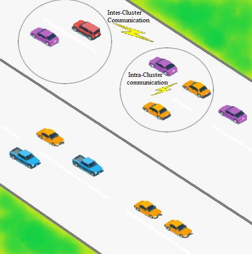
INTERNATIONAL JOURNAL OF CIRCUITS, SYSTEMS AND SIGNAL PROCESSING
 DOI: 10.46300/9106.2021.15.15 Volume 15, 2021

 II. DEVELOPED VEHICLE TO VEHICLE MULTI-AGENT SYSTEM
 One possible platform for communication between the We have further developed the multi-agent system that we
vehicles is through the usage of the GSM network at different conceptually put forward before [39]. The main objective of the
frequencies. Also, there are other technologies such as ad hoc work is to build a multi-agent system with noise immunity that
short range communications. Short range communications are can successively transmit data and decisions between vehicles.
used to alert drivers of potential problems at a distance of 300 The vehicles in the developed system are divided into several
meters. This connection can enhance the functionality of virtual groups called clusters as shown in Figure 1. Each cluster
adaptive cruise control systems. Wireless communication is formed from the head of the group, which is the main vehicle
technology is another popular technology that allows vehicles that sends the signal and group members who are the rest of the
to exchange data (Wi-Fi wireless technology) using high-speed vehicles that fall within the power coverage range of the main
networks. The consensus of many stakeholders that the vehicle.
marketing advantage provided by advanced driver assistance
systems is very important in communication between vehicles.
 A multi-agent system is developed in this paper for vehicle
to vehicle communication in a noisy environment. The multi-
system system has been a hot topic in recent years [39-43]. It
remains a field of research and development due to its great
influence and pioneering applications in matters related to
security, human safety and facilitating life. The developed
system consists of a group of agents who share information and
decisions and proactively help each other to achieve the goal of
driver comfort and safety. The agents in the developed system
will be equipped with intelligent decision maker that arms the
agents with the reasoning capability that can assist in making
instantaneous decisions that protect vehicles and facilitate
traffic. Having a smart communication system makes
communication between vehicles faster and better.
 Wireless communication channels become an integral part of
communication between vehicles. The existence of
communication channels requires signal sampling, quantizing,
and estimation. This adds new dynamic behavior to the
developed multi-agent system.
 Obeidat et al. in [44], [45] and [46] developed a new Fig. 1. An illustrative structure of vehicular networks.
methodology for real-time control-oriented identification and
signal estimation using quantitative sensing information.
PMDC motors were used to develop the system, where PMDC The communication between clusters takes place between
motors are the most important parts used in electric and hybrid the first main vehicle from the first cluster and the first main
transmission and their auxiliary subsystems. This study resulted vehicle from the second cluster. Communication within a
in reducing the system sensing costs and communication cluster (intra cluster communication) or between clusters (inter
resource consumption; also, the system reliability was cluster communication) is primarily intended to successfully
 send data to the destination.
enhanced by simplifying system configuration and packaging.
 Figure 2 shows the structure of the developed Vehicle
 In [47], Authors develop an identification system that
 Monitoring Agents (VMA). The main components of VMA are
collects data on braking system using DC servo motor. This
 decision maker unit, deliberative engine, knowledge bases and
assists drivers to avoid sudden braking accidents. communication module. More details of these components are
 In order to preserve the safety of drivers and vehicles, an found in our previous work [39]. Interaction between Vehicle
intelligent communication system must be developed to reduce Monitoring Agents occurs within a scene. A VMA can
accidents on the roads [47]. One of Salient features in machine communicate with other VMAs in the same or different driving
learning approach related to vehicle communication is to zones through communication module. The developed system
develop agents that deal with large variety of threats [48]. is composed from several scenes based on the readings of the
 In this paper, Vehicle-to-Vehicle communication system is is sensors. The scenes and sensors readings are stored in
designed to transfer and share information between vehicles knowledge databases. A protocol of a scene is considered to be
such that, the system delivers warning signals for drivers and the specification of the possible dialogues that participating
other vehicles. The develop system consists of three parts. The agents have. Possible dialogues are managed by deliberative
first part is the development of multi agent system in noisy engine.
environment. The second part is the decision system to predict
the alarm percentage of a vehicle. The last part is the
implementation of the system.

 E-ISSN: 1998-4464 136
INTERNATIONAL JOURNAL OF CIRCUITS, SYSTEMS AND SIGNAL PROCESSING
DOI: 10.46300/9106.2021.15.15 Volume 15, 2021
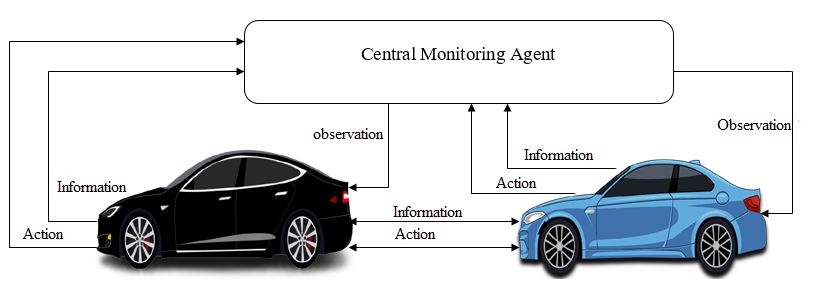
Central Monitoring Agent to get some driving environment
observations. The structure of a communication scheme is
shown in Figure 4. Agents cooperate with each other to enhance
the driving behavior and decrease the number of accidents.
Fig. 4. The structure of multi-agent communication scheme.
Fig. 2. General architecture of a Vehicle Monitoring Agent in a Wireless communication are strongly dependent on the
vehicle to vehicle multi-agent system. distance between the sender agent and receiver agent. This
affects the performance when the sensors are wirelessly
connected to the main unit. Vehicle Monitoring Agents are
A scene is described as a graph that shows the change in an able to perceive the surrounding environment, and respond in a
agent's state from one state to another. The graph contains nodes timely manner to changes that occur in it. Agents are also able
and arrows. The nodes show the different states of conversation to interact intelligently with other Vehicle Monitoring Agents.
between the agents. The arrows represent the transitions One of the main advantages of the developed multi-agent
between states. The graph contains one initial state and a set of system in use: It defines a clear structure of representing an
end states that represent different endings of the expected agent, a group of agents and messages between agents. It is
relatively easy to provide all designed agents with different
conversation in a scene. Figure 3 shows a state diagram of a
tasks [41-43], [49].
scene where Set = {S1, S2, S3, S4} a set of states in a scene:
The developed multi-agent platform encourages the use of
S1 initial state; distributed intelligence to support the vehicle to vehicle
S2 waiting for a response to the request; communication. The autonomous communication between
S3 checking the data; Vehicle Monitoring Agents has many visible and encouraging
S4 lack of communication; results, as consequence of the used decision support of NARX
S5 data processing and decision making, system. The develop decision system that is used by a VMA
is shown in Figure 5.
Fig. 3. The state diagram of a scene in multi agent environment.
In the developed multi- agent system, an agent cannot only
communicate with a single message, but also have a
“conversation.” The multi- agent environment provides Vehicle
Monitoring Agents with the ability to exchange information and Fig. 5. General architecture of Vehicle Monitoring Agent.
actions in a well-defined structure. The VMAs interact with the
E-ISSN: 1998-4464 137
INTERNATIONAL JOURNAL OF CIRCUITS, SYSTEMS AND SIGNAL PROCESSING
 DOI: 10.46300/9106.2021.15.15 Volume 15, 2021

 The monitoring data of a vehicle is gathered using real
sensors. The data is collected from engine speed sensor, oxygen
sensor, fuel temperature sensor, braking system and steering
angle sensor. The data is fed to the NARXs Decision system.
As a result, the decision system activates the braking system
either by turning it On or Off. The rotation speed of of the
engine is affected by the decision system as well. The speed is
controlled to be decreased or increased through Electric Unit
Injector Unit by injecting more or less fuel.
 The NARX decision system makes use of the historical data
gathered from driver’s behaviors in previous trips. At the same
time, the decision is sent to other surrounded vehicles through
communication module. The sent decision controls the speed of
the surrounded vehicles and activates its braking system if the
system is pre-set.

 III. DECISION MODEL USING NONLINEAR AUTOREGRESSIVE
 EXOGENOUS (NARX) NEURAL NETWORK
 Nonlinear Autoregressive Exogenous (NARX) Neural
Network is used to develop a decision model that is capable to
predict that a vehicle has abnormal behavior. The system uses
sensors data. The NARX network is suitable for the nonlinear Fig. 6. Nonlinear autoregressive exogenous neural network.
and auto-regressive nature of the vehicle sensors time series
data [50]. NARX has become popular in the last few years for The general prediction equations for computing the next
its performance in the prediction of time series. It is shown that value of time series Y(n+1) uses the past observation X 1(n),..,
NARX networks can provide optimal predictions without X1(n-k), …, XZ(n),.., Xz(n-k) and the past outputs Y(n), Y(n-1),
computational losses in comparison with the conventional …, Y(n-k) as inputs. During the training stage, the neural
recurrent neural networks (RNNs). The NARX network follows network optimize the network weights and neuron bias in order
the concept of autoregressive model in time series forecasting to get the output Y. After training, the developed model is used
[51]. It is a recurrent dynamic network, with feedback to predict the vehicle behavior.
connections to several layers of the network [52]. A relevant The most common learning rule for the NARX network is
study can be found in [53]. the Levenberg-Marquardt Algorithm. The Levenberg–
 The NARX network is a feed forward neural network with Marquardt (LM) algorithm is a back propagation algorithm. It
three layers; input, hidden, and output layers. NARX network has been widely used for training the NARX network because
is used to solve a time series problem. NARX neural network of the fast convergence speed. The LM algorithm uses an
uses historical data of the variable in order to make decision. approximation of the Hessian matrix without direct calculation,
The topology of a NARX network is shown in Figure 6. The therefore its training speed is increased. The LM equation to
number of delays and the number of neurons in the hidden layer update the weights is shown in (2),
are adjustable. These numbers are optimized through trial-and-
error testing in order to get accurate model responses. wk+1 = wk − [J T J + δI]−1 J T e(wk ) (2)
Future values of time series values y(n) are predicted based on
its delays values as shown in (1), where J is the Jacobian matrix, I is the identity matrix, and e is
 the network errors. The Jacobian matrix is the first derivatives
 ( ) = ∑
 =1 ∗ [ (∑ =1 ( − ) + 0 ) + of the error with respect the weights wk . The Hessian matrix is
 (∑ =1 ( − ) + 0 ) +] + 0 + (1) JTJ and the gradient is JTe. The effectiveness of the model is
 measured by using mean squared error (MSE) and (R2) as
Where k is the number of delays, m is the number of neurons in shown in (3) and (4) respectively.
a hidden layers with activation function f, and wij is the weight
 1
of the connection between the input i and the hidden neuron j. MSE = ∑i(yi − ŷ)2 (3)
 n
wj is the weight between the hidden neuron j and the output 2 ̂)2
 ∑i(yi−y
layer. woj is the initial weights (bias) between input layer and j R = 1− (4)
 ̅)2
 ∑i(yi−y
neuron in the hidden layer, and wo is the initial weight of the
output layer. is the error of the approximation of the series at Where yi is the actual value of the sample i and n is the number
a given time. The most commonly used activation function f in of samples, ̂ is the forecasted value and ̅ is the average value.
neural network is Sigmoid function. When the resulted amount of these equations is small, the
 performance of prediction is better. The developed algorithm is
 summarized in Figure 7.

 E-ISSN: 1998-4464 138
INTERNATIONAL JOURNAL OF CIRCUITS, SYSTEMS AND SIGNAL PROCESSING
 DOI: 10.46300/9106.2021.15.15 Volume 15, 2021

Vehicle Behavior Prediction Algorithm used in signal recovery schemes. It is used to reduce signal
 estimation errors and eliminate noises on the transmitted
1: Read sensors data signals.
2: Prepare data for training and simulation The used signal estimation methodology is introduced in
3: Setup data division for training, testing, and validation [45], and [46]. This estimation algorithm has not been used
4: Create NARX neural network model previously in a multi-agent system. It is shown in [45] that the
5: Choose number of delays and number of neurons in hidden algorithms which extract information on the original signals act
layer as averaging filters. Low-precision quantization, such as
6: Choose a performance function binary-valued quantization, will not transmit sufficient
7: Train, test, and validate the model information on the signals for feedback control. However, more
8: Run performance checking information is recovered by employing the smoothing effects of
9: if passes then random noises.
10: Select model specification
 The output transmitted signal is denoted by Lk. The true
12: else
 transmitted signal υ is bounded L ≤ L ≤ L . L is
13 Repeat step 7
14: end if either affected with a measurement noise or with a random
15: Return specification and model ready for decision noise added to enhance signal estimation.
 The signal with added noise Lk + N is quantized to get a a
 Fig. 7. Vehicle behavior prediction algorithm. quantization function S(Lk + N).The signal Lk + Nk is
 quantized by Q quantization thresholds {h1. . . hQ}, which
 divides the range [Lmin, Lmax] into Lmin < h1 < · · · < hQ < Lmax.
 IV. MULTI-AGENT SYSTEM IN A NOISY ENVIRONMENT The output of the quantizer takes Q + 1 possible values which
 are represented in the set ={1, 2, . . . ,Q+ 1}. The resulted signal
 When a signal is transmitted to the surrounded vehicles, it is
 is represented in (5),
sampled, quantized, and then transmitted through
communication module of a vehicle Monitoring Agent to other
Vehicles Monitoring Agent and Central Monitoring Agent as sk = ∑m+1
 i i ∗ Ihi−1 h
 The data point sk sent at time tk is arrived with a delay and a
 random noise to the the other VMA. The data sequence is not
 altered due to time-varying delays as a result of FIFO (first-in-
 first-out) buffers. The binary valued quantization is used to
 estimate the transmitted signals between vehicles with correct
 order. (7) defines the exponentially weighted empirical
 Fig. 8. Closed loop VMA to VMA communication system. measures if 0 < α < 1,

 = (1 − ) ∑ =−∞ −1 (7)

 where the weight is normalized as in (8),

 ℎ sl = 1, (1 − α) ∑∞ l
 l=0 α = 1 (8)

 Algorithm can also be written recursively as shown in (9),
 Fig. 9. Closed loop VMA to Central Monitoring Agent
 communication system.
 = −1 + (1 − )( − −1 )
 At the receiving Vehicle Monitoring Agent, the signal is
recovered and estimated. Communication channels encounter
 = λΔk−1 + β(sk − λΔk−1 ) (9)
time delays and noise. The used method for estimating the
transmitted signals is averaging method, which is commonly

 E-ISSN: 1998-4464 139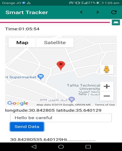
INTERNATIONAL JOURNAL OF CIRCUITS, SYSTEMS AND SIGNAL PROCESSING
DOI: 10.46300/9106.2021.15.15 Volume 15, 2021
The signal estimating algorithm uses constant step size Multiple messages are also be sent to the Central
β = 1 − α. The smaller the α value, the faster the decaying rate. Transportation Agency, Civil defense unit or Police station with
For some small δ satisfying 0 < δ < 1, is defined in (10) GPS location of vehicle.
Δ
λΔk , δ < λk < 1 − δ,
λk = { δ, λΔk < δ, } (10)
1 − δ, λΔk > 1 − δ,
The estimation of Lk is shown in (11)
L̂k = h − G−1 (λk ) (11)
The used signal-averaging filter is in (12)
(1− )
F= (12)
−
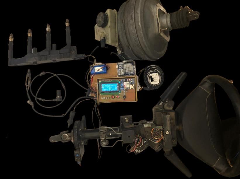
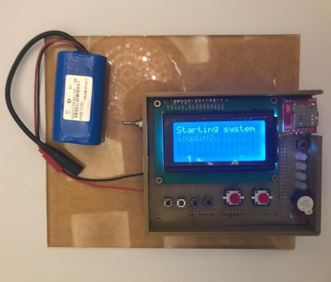
V. IMPLEMENTATION OF THE SYSTEM Fig. 10. Vehicle Assistant Agent.
A prototype design for vehicle- vehicle communication A central processor is provided to the car to control the
system is successfully developed. Arduino is used as a base of engine's working mechanism. This is done through the
the multi agent network because of its simplicity and cost. availability of a good number of sensors. For example, the fuel
Arduino is combined with different wireless technologies in delivery to the engine is controlled, the emissions are
order to build a network. For inter clusters communication monitored, and the anti-slip brakes are activated when needed.
between GSM is used. While Radio Frequency (RF) module is The oxygen sensor (Figure 11) is located in the exhaust pipe.
used in intra cluster communication. Each sensor will transmit The oxygen sensor monitors the content of gases emitted from
its data value to a main unit where the data get processed and the exhaust by measuring the amount of unburden oxygen in the
usedto make a decision in order to be sent to other vehicles. exhaust pipe. This information is used to find out if the engine
With the developed system, neighbors' vehicles can get the is running with rich or lean fuel content. The Electric Unit
up-to-date alarm level of surrounding vehicles by receiving an Injector Unit uses this information to determine fuel metering
SMS. SMS messages offer an interesting solution. Messages strategy and emission controls.
are delivered within seconds. This allows the vehicle to obtain
details of abnormal driving alarms before unforeseen situations.
The Vehicle Assistant Agent shown in Figure 10 consists of
vehicle sensors connected to the sensor unit which interact with
data collection unit, the microcontroller unit, the GSM module,
and the RF module unit. The sensors are connected to a data
gathering unit which is connected to a microcontroller. The
collected data from sensors is used by the microcontroller to
make decisions about driving behavior and verify that it is
within safe levels.
In the event that the driving behavior is abnormal, the
microcontroller unit immediately activates the alarm by
operating the buzzer alarm unit and the LED unit begins Fig. 11 Oxygen sensor.
flashing. At the same time, an alert message will be sent by the
microcontroller unit to other vehicles. The data collected from The engine speed sensor (Figure 12) measures the rotational
the sensors will be displayed in front of the vehicle's driver on speed of the crankshaft itself in RPMs. In order for this sensor
the LCD unit. to work, there must be a serrated disk and a magnetic coil. As
the crank rotates, an electric current is created to generate a
magnetic field around the coil. These movements disrupts the
magnetic fields and these disruptions are counted into RPM.
E-ISSN: 1998-4464 140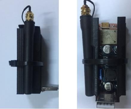
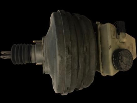
INTERNATIONAL JOURNAL OF CIRCUITS, SYSTEMS AND SIGNAL PROCESSING
 DOI: 10.46300/9106.2021.15.15 Volume 15, 2021

 principle allows measuring the angle range without using a
 rotation counter.
 Based on the signals received from the main brake servo
 cylinder (Figure 15) and the pressure sensor on it, Electronic
 Control Unit (ECU) calculates the speed and amount of brake
 pedal force to determine the driver's intention to perform
 emergency braking.

 Fig. 12. Engine speed sensor.

 The fuel temperature sensor (Figure 13) sends the fuel
Temperature to the vehicle Electronic Control Unit (ECU) to
specify the amount of fuel to be delivered. Warmer fuels will
be less dense and will ignite more quickly than colder fuel
which is more dense. If the fuel is warm, the injectors will save
more fuel to reach a certain level of mass. A non-functioning
fuel temperature sensor leads to a decrease in fuel economy.

 Fig. 15. Layout of an electro hydraulic braking system.

 The work of the cylinder converts the force applied from the
 brake pedal into pressure in the brake fluid, and pushes the fluid
 Fig. 13. Fuel temperature sensor. from it into the brake tubes and into the wheels' cylinders. The
 cylinder is mostly made of aluminum alloy (Figure 16), and the
 cylinder is fixed either to the plate separating the engine
 The steering angle sensor (Figure 14) is based on Giant compartment and the passenger compartment of the vehicle by
Magneto-Resistance technology. The unique feature of the means of fixed bolts.
steering angle sensor is to provide an absolute steering angle
value. The steering angle sensor is installed on the steering
shaft. The hub gear wheel transfers the rotational motion of the
shaft to two measuring gear wheels. On each measuring gear
wheel, a magnet is installed. The direction of its magnetic field
changes according to the rotational motion. Below each magnet
is a GMR sensor element to detect the angle position of the
magnet above.

 Fig. 16. Brake servo unit.

 Spark plug in Ignition spark plug with ignition control unit
 (Figure 17) has two electrodes which are immersed inside the
 combustion chamber of gasoline engine (internal combustion
 engine). To activate the spark plug, it should get the signal
 either from the distributor or through the ECU. Distributor
 rotates and determine when butterfly touches and when to
 disconnect to give the high voltage to the right spark in any
 cylinder. Based on the firing order ECU get signals from
 different sensors inside the combustion chamber or on the crank
 shaft or camshaft that gives a signal to the ignition coil to send
 high or low voltage to the spark. Spark plug gets its high voltage
 from the ignition coil. Before getting the high voltage, the fuel
 Fig. 14. Steering angle sensor on steering shaft. air mixture will be working as an insulator in the front of the
 gap of the spark plug. As the voltage increased the gas get
 The sensed values are converted into digital information ionized and starts conducting current which will heat up the gas
directly to be sent to the microprocessor. This measuring causing an initiation of the ignition process. The flame will

 E-ISSN: 1998-4464 141

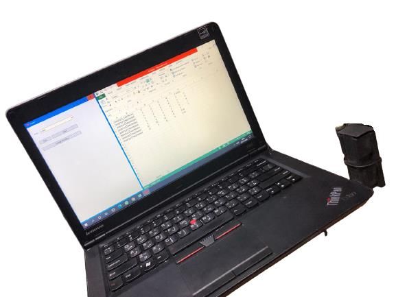
INTERNATIONAL JOURNAL OF CIRCUITS, SYSTEMS AND SIGNAL PROCESSING
 DOI: 10.46300/9106.2021.15.15 Volume 15, 2021

propagate as fast as possible to ignite the whole mixture in the
combustion chamber. As the engine speed increased the new
charge will enter to the combustion chamber faster and faster,
and thus there might be less time for the flame to cover the
whole combustion chamber region

 Fig. 19. Central Transportation Agent architecture.

 The sensors reading is also accessed through OBD port. It
 can be wired or wireless through Bluetooth scanner as shown in
 Figure 20. OBD system is a computer-based system developed
 by automobile manufacturers to monitor the performance of
 Fig. 17. Ignition spark plug with ignition control unit. various components on a vehicle's engine. The main
 components of the OBD system are: ECU, connectors that send
 The Receiving alarm unit (Figure 18) receives the data to the electronic control unit, sensors, malfunction
transmitted data, supported by the initial decision taken by its indicator lights and OBD port to get the sensors readings.
VMA. Accordingly, the microcontroller unit starts
communicating with the other units attached to it, such as the
buzzer alarm unit, the LEDs unit and the LCD screen unit to
show the result of the initial decision taken. If the driving risk
value is high, the buzzer will be activated, the LED will start to
flash and the LCD screen will display the information of the
vehicle causing this warning to take caution.

 Fig. 20. Data link connector using OBD.

 A prototype design for a wireless receiving unit to be used by
 database has been successfully developed and implemented.
 Database represents central vehicles database that is responsible
 for storing vehicles data. Figure 21 shows the wireless receiving
 unit prototype.

 Fig. 18. Receiving alarm unit.

 The decision depends on the output of the NARX. In all
moments, the Central Transportation Agent can access the
network through the graphical user interface as shown in Figure
19. One of the most important components of this agent is the
logging and security unit, which allows only authorized persons Fig. 21. Wireless receiving unit.
to access the system. In addition there are other parts which are
similar to the VMA, such as the data processing unit and the Figure 22 shows the Wireless Receiving Unit prototype
rule based engine which is decision-making unit. The system connected to laptop (i.e. central database).
can be accessed either via a web browser or an application on
the mobile device.

 E-ISSN: 1998-4464 142
INTERNATIONAL JOURNAL OF CIRCUITS, SYSTEMS AND SIGNAL PROCESSING
 DOI: 10.46300/9106.2021.15.15 Volume 15, 2021

 Table 1. General form of confusion matrix
 Actual Transmitted Class
 Predicte Class=Normal Class=Abnormal
 d
 Class=Normal True Positive False Positive
 Received
 (TP) (FP)
 Class
 Class=Abnormal False True
 Negative (FN) Negative(TN)

 The used performance measurements are recall, precision,
 and accuracy. Recall (R) is the ratio of successfully retrieved
 data among the relevant. Precision (P) is the ratio of the relevant
 data among the retrieved data. Accuracy, which indicates the
 fraction of correctly classified samples among all the samples.
 The formulas are given in (13), (14) and (15) as follow,
 Fig. 22. Central database unit with wireless receiving unit.

A mobile application (Figure 23) is developed to locate and Recall(R) = if TP+FN > 0. (13)
 +
alarm a Vehicle with abnormal driving behavior. It has the
ability to send messages to warn the vehicle. TP
 Precision(P) = if TP+FP > 0, (14)
 TP +FP

 TP +TN
 Accuracy = (15)
 TP +TN +FP +FN

 The Kappa coefficient is an estimate of the agreement
 between two raters. Kappa scores range between 1 (complete
 agreement) and 0. [54] suggested that there is excellent
 agreement for values of Kappa greater than 0.75, poor
 agreement for values less than 0.4, and fair to good agreement
 for values between 0.40 and 0.75.
 This experiment uses 24 hours driving trips. Each three
 seconds an alarm level class is transmitted between two Vehicle
 Monitoring Agents. The total number of transmitted classes 480
 values. Its values are either normal and abnormal. The resulted
 confusion matrix is shown in Table 2.

 Table 2. Confusion matrix of the 24 hours driving experiment
 Actual Transmitted Class
 Fig. 23. Screenshot of a text message received from Central
 Class Class Predicted Precision
 Monitoring Agent to a vehicle driver.
 Normal Abnormal Overall
 Predicted Received

 Class 314 5 319 98.43%
 Normal
 Class

 VI. EXPERIMENTS AND RESULTS Class 6 155 161 96.27%
 To firmly examine the proposed agent system and Abnormal
demonstrate its effective capability for communication, we Actual 320 120 480
 Overall
conducted some evaluation experiments. In an experiment, the
 Recall 98.12% 96.87%
first and second Vehicle Monitoring Agents initially registers
 Overall 97.71%
with a Central Monitoring Agent. Then the two Vehicle
 accuracy
Monitoring Agents start communicating with each other to
 Kappa 0.949
exchange decisions between vehicles such as alarm level. The
multi-agent system works successfully as designed.
 We examined agreement between the transmitted signal of a In neural networks, choosing type of input variables is as
Vehicle Monitoring Agent and the received signal of another important as choosing appropriate type of neural network and
Vehicle Monitoring Agent. The confusion matrix for each class the relevant learning algorithm, It is because if the input
(normal or abnormal alarm level). The confusion matrix has variables are not chosen appropriately, neural network may be
the form shown in Table 1. stopped at the same stage of learning [50]. The NARX model
 requires less past information than other neural network models
 to achieve an accurate prediction [50] and [51]. The goal of this
 experiment was to measure how well the developed system
 performed in decision-making.

 E-ISSN: 1998-4464 143
INTERNATIONAL JOURNAL OF CIRCUITS, SYSTEMS AND SIGNAL PROCESSING
 DOI: 10.46300/9106.2021.15.15 Volume 15, 2021

 To assess the effectiveness of the developed decision-making
unit, NARX has been trained using 88 driving trips with 1440 Steering Angle
records (24 hours) for five sensors data engine speed; oxygen
sensor, fuel temperature, steering angle, and brake pedal force. 3

 Steering Angle (degree)
Figure 24 to Figure 28 show one hour of a collected data for the 2
five sensors in a trip.
 1

 1250 0
 0 10 20 30 40 50 60
 Engine Speed (rpm)

 1200 -1
 1150 -2
 Time(min)
 1100
 1050 Fig. 27. Steering angle (degree).
 1000
 950 12

 Brake Pedal Force (N)
 0 10 20 30 40 50 60 10
 Time (min) 8
 6
 Fig. 24. Engine speed (rpm).
 4
 2
 0,7
 0
 Oxygen Sensor Reading (volt)

 0,6 0 10 20 30 40 50 60
 0,5 Time (min)
 0,4
 0,3 Fig. 28. Brake pedal force (N).
 0,2
 0,1 The alarm percentage (%) of a vehicle is noticed and
 0 recorded based on sensor data by two domain experts. If the
 0 10 20 30 40 50 60 alarm percentage (%) is greater than 75%, it will be considered
 Time (min) as abnormal. Otherwise, it will be considered as normal. The
 alarm percentage (%) of a 60 minutes trip is shown in Figure
 Fig. 25. Oxygen sensor reading (volt). 29.

 325 100
 Alarm Percentage (%)
 Fuel Temperature (c)

 320 80

 315 60
 40
 310
 20
 305
 0
 300 0 20 40 60
 295 Time (min)
 0 10 20 30 40 50 60 Alarm Level Alarm (%)
 Time (min)
 Fig. 29. Alarm percentage (%).
 Fig. 26. Fuel temperature (Co).
 The collected data is divided into three parts: 70% for
 training, 15% for testing, and 15% for validation. During the
 training step the true output, or measured value, is used as the
 regressive input in the network. Once the network is trained and
 used for prediction purposes, the calculated output was

 E-ISSN: 1998-4464 144
INTERNATIONAL JOURNAL OF CIRCUITS, SYSTEMS AND SIGNAL PROCESSING
 DOI: 10.46300/9106.2021.15.15 Volume 15, 2021

feedback to the network to obtain the estimation for the next Table 4. Number of neuron in hidden layer and
prediction step. Figure 30 shows real and a predicted alarm Epoch and R
percentage. It is clearly noticed that the predicted alarm Number of Epoch R
percentage is very close to the real alarm percentage signal. neuron in
This shows that NARX is able to predict the alarm percentage hidden layer
using the five inputs. 3 55 0.25
 5 40 0.33
 9 81 0.45
 15 14 0.64
 20 22 0.78
 25 27 0.89
 30 12 1

 Figure 31 shows the prediction of a 3-minute alarm
 percentage. This prediction is done using the developed NARX
 model. It helps protect vehicle drivers from a problem that may
 occur during the trip. In addition, it provides the necessary
 information that assist in avoiding an event that may lead to
 interruption of traffic.

 Fig. 30. Real and predicted alarm percentage (%) by NARX.

 The initial weights in the network are assigned randomly, and
they are adjusted at each iteration (i.e., epoch) to reduce the
error. The procedure continued until the network output met the
stopping criteria. The developed NARX model consists of one
input layer, one hidden layer, and one output layer. The NARXs
are based on LM back-propagation training making decision.
MATLAB® software is used to build the models. The NARX
structure with 30 hidden neurons was found to be the most
effective. It must be noted that increasing the number of
neurons in the hidden layer makes a system more complex.
Decreasing the number of neurons in the hidden layer will
 Fig. 31. Three minutes alarm percentage (%) prediction.
lower the computing power. Decision results of NARX with
n=30 neurons in hidden layer and different numbers of delay VII. CONCLUSION
are shown in Table 3.
 In this paper, a multi agent system is developed to provide a
 Table 3. Number of delays and epoch and R robust vehicle to vehicle communication system in a noisy
 Delay Epoch R environment. The developed system has a decision mechanism
 1 22 0.32 which is based on NARX neural network. Vehicle Monitoring
 Agents and Central Monitoring Agent are implemented. The
 3 15 0.93
 developed system was tested using real driver data collected
 5 12 1 during real trips. The system performs as designed. It succeeded
 8 43 0.8 in providing a predicted alarm percentage to the vehicle driver
 10 91 0.63 and correctly sending it to the surrounding vehicles.
 12 31 0.78
 15 75 0.48 ACKNOWLEDGMENT
 The author wishes to express his thanks for the support of
 NARX performs best when delay is set 5. This means that 5 Tafila Technical University. Also, the author is very grateful for
earlier records are meaningful to future detection. When the the support of Anwar Makka company for providing the
delay is larger than 5, it will cause over fit issue which makes vehicles parts used in the conducted experiments.
the trained network less adaptable. Results of NARX with
delay=5 and different numbers of neuron in hidden layer are
shown in Table 4.

 E-ISSN: 1998-4464 145
INTERNATIONAL JOURNAL OF CIRCUITS, SYSTEMS AND SIGNAL PROCESSING
 DOI: 10.46300/9106.2021.15.15 Volume 15, 2021

 References [14] H. A. Ameen et al., "A Deep Review and Analysis of Data
[1] M. A. Masrur et al., "Military-Based Vehicle-to-Grid and Exchange in Vehicle-to-Vehicle Communications
 Vehicle-to-Vehicle Microgrid—System Architecture and Systems: Coherent Taxonomy, Challenges, Motivations,
 Implementation," in IEEE Transactions on Transportation Recommendations, Substantial Analysis and Future
 Electrification, vol. 4, no. 1, pp. 157-171, March 2018. Directions," in IEEE Access, vol. 7, pp. 158349-158378,
[2] J. Thunberg, N. Lyamin, K. Sjöberg and A. Vinel, 2019.
 "Vehicle-to-Vehicle Communications for Platooning: [15] T. Limbasiya and D. Das, "Lightweight Secure Message
 Safety Analysis," in IEEE Networking Letters, vol. 1, no. Broadcasting Protocol for Vehicle-to-Vehicle
 4, pp. 168-172, Dec. 2019. Communication," in IEEE Systems Journal, vol. 14, no. 1,
[3] W. Shieh, C. J. Hsu, C. Lin and T. Wang, "Investigation of pp. 520-529, March 2020.
 Vehicle Positioning by Infrared Signal-Direction [16] J. He, Z. Tang, Z. Fan and J. Zhang, "Enhanced Collision
 Discrimination for Short-Range Vehicle-to-Vehicle Avoidance for Distributed LTE Vehicle to Vehicle
 Communications," in IEEE Transactions on Vehicular Broadcast Communications," in IEEE Communications
 Technology, vol. 67, no. 12, pp. 11563-11574, Dec. 2018. Letters, vol. 22, no. 3, pp. 630-633, March 2018.
[4] K. Guan et al., "5-GHz Obstructed Vehicle-to-Vehicle [17] Z. Ma, Q. Huo, X. Yang and X. Zhao, "Safety Cruise
 Channel Characterization for Internet of Intelligent Control of Connected Vehicles Using Radar and Vehicle-
 Vehicles," in IEEE Internet of Things Journal, vol. 6, no. to-Vehicle Communication," in IEEE Systems Journal,
 1, pp. 100-110, Feb. 2019. vol. 14, no. 3, pp. 4602-4613, Sept. 2020.
[5] Y. S. Lam, J. J. Q. Yu, Y. Hou and V. O. K. Li, [18] J. Zhou, Z. Chen, H. Jiang and H. Kikuchi, "Channel
 "Coordinated Autonomous Vehicle Parking for Vehicle-to- modelling for vehicle-to-vehicle MIMO communications
 Grid Services: Formulation and Distributed Algorithm," in in geometrical rectangular tunnel scenarios," in IET
 IEEE Transactions on Smart Grid, vol. 9, no. 5, pp. 4356- Communications, vol. 14, no. 19, pp. 3420-3427, 1 12
 4366, Sept. 2018. 2020.
[6] L. Zhang and G. Orosz, "Beyond-Line-of-Sight [19] X. Mou, D. T. Gladwin, R. Zhao, H. Sun and Z. Yang,
 Identification by Using Vehicle-to-Vehicle "Coil Design for Wireless Vehicle-to-Vehicle Charging
 Communication," in IEEE Transactions on Intelligent Systems," in IEEE Access, vol. 8, pp. 172723-172733,
 Transportation Systems, vol. 19, no. 6, pp. 1962-1972, 2020.
 June 2018. [20] S. Hung, X. Zhang, A. Festag, K. Chen and G. Fettweis,
[7] J. Pachat, N. S. Karat, P. P. Deepthi and B. S. Rajan, "Index "Vehicle-Centric Network Association in Heterogeneous
 Coding in Vehicle to Vehicle Communication," in IEEE Vehicle-to-Vehicle Networks," in IEEE Transactions on
 Transactions on Vehicular Technology, vol. 69, no. 10, pp. Vehicular Technology, vol. 68, no. 6, pp. 5981-5996, June
 11926-11936, Oct. 2020. 2019.
[8] W. B. Qin and G. Orosz, "Experimental Validation of [21] H. Mei, J. Ding, J. Zheng, X. Chen and W. Liu, "Overview
 String Stability for Connected Vehicles Subject to of Vehicle Optical Wireless Communications," in IEEE
 Information Delay," in IEEE Transactions on Control Access, vol. 8, pp. 173461-173480, 2020.
 Systems Technology, vol. 28, no. 4, pp. 1203-1217, July [22] B. Fan, H. Tian, S. Zhu, Y. Chen and X. Zhu, "Traffic-
 2020. Aware Relay Vehicle Selection in Millimeter-Wave
[9] C. R. Storck and F. Duarte-Figueiredo, "A Survey of 5G Vehicle-to-Vehicle Communication," in IEEE Wireless
 Technology Evolution, Standards, and Infrastructure Communications Letters, vol. 8, no. 2, pp. 400-403, April
 Associated With Vehicle-to-Everything Communications 2019.
 by Internet of Vehicles," in IEEE Access, vol. 8, pp. [23] L. Zhang, "Cooperative adaptive cruise control in mixed
 117593-117614, 2020. traffic with selective use of vehicle-to-vehicle
[10] H. Jiang, Z. Zhang, L. Wu and J. Dang, "A Non-Stationary communication," in IET Intelligent Transport Systems,
 Geometry-Based Scattering Vehicle-to-Vehicle MIMO vol. 12, no. 10, pp. 1243-1254, 12 2018.
 Channel Model," in IEEE Communications Letters, vol. [24] J. Lan and D. Zhao, "Min-Max Model Predictive Vehicle
 22, no. 7, pp. 1510-1513, July 2018. Platooning With Communication Delay," in IEEE
[11] H. Ko, S. Pack and V. C. M. Leung, "Mobility-Aware Transactions on Vehicular Technology, vol. 69, no. 11, pp.
 Vehicle-to-Grid Control Algorithm in Microgrids," in 12570-12584, Nov. 2020.
 IEEE Transactions on Intelligent Transportation Systems, [25] G. Fiengo, D. G. Lui, A. Petrillo, S. Santini and M. Tufo,
 vol. 19, no. 7, pp. 2165-2174, July 2018. "Distributed Robust PID Control For Leader Tracking in
[12] H. Jiang, Z. Zhang, L. Wu and J. Dang, "Novel 3-D Uncertain Connected Ground Vehicles With V2V
 Irregular-Shaped Geometry-Based Channel Modeling for Communication Delay," in IEEE/ASME Transactions on
 Semi-Ellipsoid Vehicle-to-Vehicle Scattering Mechatronics, vol. 24, no. 3, pp. 1153-1165, June 2019.
 Environments," in IEEE Wireless Communications [26] H. Nguyen et al., "Impact of Big Vehicle Shadowing on
 Letters, vol. 7, no. 5, pp. 836-839, Oct. 2018. Vehicle-to-Vehicle Communications," in IEEE
[13] Z. Liu, Y. Xie, Y. Yuan, K. Ma, K. Y. Chan and X. Guan, Transactions on Vehicular Technology, vol. 69, no. 7, pp.
 "Robust Power Control for Clustering-Based Vehicle-to- 6902-6915, July 2020.
 Vehicle Communication," in IEEE Systems Journal, vol. [27] V. -L. Nguyen, P. -C. Lin and R. -H. Hwang, "Enhancing
 14, no. 2, pp. 2557-2568, June 2020. Misbehavior Detection in 5G Vehicle-to-Vehicle

 E-ISSN: 1998-4464 146
INTERNATIONAL JOURNAL OF CIRCUITS, SYSTEMS AND SIGNAL PROCESSING
 DOI: 10.46300/9106.2021.15.15 Volume 15, 2021

 Communications," in IEEE Transactions on Vehicular [41] Bilal Hawashin, and Ayman Mansour, "An Efficient
 Technology, vol. 69, no. 9, pp. 9417-9430, Sept. 2020. Agent-Based System to Extract Interests of User Groups,"
[28] Z. Liu, X. Han, Y. Liu and Y. Wang, "D2D-Based Lecture Notes in Engineering and Computer Science:
 Vehicular Communication With Delayed CSI Feedback," Proceedings of The World Congress on Engineering and
 in IEEE Access, vol. 6, pp. 52857-52866, 2018. Computer Science, vol. 1, pp. 444-448, October 2016.
[29] H. Jiang, Z. Zhang, L. Wu, J. Dang and G. Gui, "A 3-D [42] Ayman Mansour, Hao Ying, Peter Dews, Yanqing Ji, and
 Non-Stationary Wideband Geometry-Based Channel R. Michael Massanari, "Identifying Adverse Drug
 Model for MIMO Vehicle-to-Vehicle Communications in Reaction Signal Pairs by a Multi-Agent Intelligent System
 Tunnel Environments," in IEEE Transactions on Vehicular with Fuzzy Decision Model," Proceedings of the 31st
 Technology, vol. 68, no. 7, pp. 6257-6271, July 2019. North American Fuzzy Information Processing Society
[30] Rashdan, F. de Ponte Müller, S. Sand, T. Jost and G. Caire, Conference, Berkeley, CA, August 6-8, 2012.
 "Measurement-based geometrical characterisation of the [43] Ayman Mansour, Hao Ying, Peter Dews, Yanqing Ji,
 vehicle-to-vulnerable-road-user communication channel," Margo Farber, John Yen, Richard E. Miller, and R.
 in IET Microwaves, Antennas & Propagation, vol. 14, no. Michael Massanari, "A Multi-Agent System for Detecting
 14, pp. 1700-1710, 25 11 2020. Adverse Drug Reactions," Proceedings of the 29th North
[31] M. Yang et al., "A Cluster-Based Three-Dimensional American Fuzzy Information Processing Society
 Channel Model for Vehicle-to-Vehicle Communications," Conference, Toronto, ON, Canada, July 12-14, 2010.
 in IEEE Transactions on Vehicular Technology, vol. 68, [44] Mohammad A Obeidat, L.Y. Wang, F. Lin, “Real-Time
 no. 6, pp. 5208-5220, June 2019. Parameter Estimation of PMDC Motors using Quantized
[32] S. Gill, B. Aygun, K. N. Heath, R. J. Gegear, E. F. Ryder Sensors,” IEEE Transactions on Vehicular Technology,
 and A. M. Wyglinski, "Memory Matters: Bumblebee Vol. 62, no. 6, pp. 1- 10, July 2013.
 Behavioral Models for Vehicle-to-Vehicle [45] Mohammad A Obeidat, L.Y. Wang, F. Lin, Online
 Communications," in IEEE Access, vol. 6, pp. 25437- Parameter Estimation of PMDC Motors using Quantized
 25447, 2018. Output Observations, ITEC IEEE Transportation
[33] Alturiman and M. Alsabaan, "Impact of Two-Way Electrification Conference, Dearborn, Dearborn,
 Communication of Traffic Light Signal-to-Vehicle on the Michigan, June 18-20, 2012.
 Electric Vehicle State of Charge," in IEEE Access, vol. 7, [46] Mohammad A Obeidat, L.Y. Wang, F. Lin, ”On-Line
 pp. 8570-8581, 2019. Parameter Estimation of PMDC Motors using Binary-
[34] H. Jiang, W. Ying, J. Zhou and G. Shao, "A 3D Wideband Valued Speed Measurements, PECI Power and Energy
 Two-Cluster Channel Model for Massive MIMO Vehicle- Conference at Illinois, University of Illinois at Urbana
 to-Vehicle Communications in Semi-Ellipsoid Champaign, Illinois, February 24-25, 2012.
 Environments," in IEEE Access, vol. 8, pp. 23594-23600, [47] Mohammad A Obeidat, “Real-Time DC Servomotor
 2020. Identification and Control of Mechanical Braking System
[35] V. Hassija, V. Chamola, G. Han, J. J. P. C. Rodrigues and for Vehicle-to-Vehicle Communication,” International
 M. Guizani, "DAGIoV: A Framework for Vehicle to Journal of Computer Applications, Vol. 182, no. 40, PP.
 Vehicle Communication Using Directed Acyclic Graph 20-30, February 2019.
 and Game Theory," in IEEE Transactions on Vehicular [48] Zeinab El-Rewini, Karthikeyan Sadatsharan, Daisy Flora
 Technology, vol. 69, no. 4, pp. 4182-4191, April 2020. Selvaraj, Siby Jose Plathottam, Prakash
[36] B. Zhou et al., "Optimal Coordination of Electric Vehicles Ranganathan,”Cybersecurity challenges in vehicular
 for Virtual Power Plants With Dynamic Communication communications,” Vehicular Communications, Vol. 23,
 Spectrum Allocation," in IEEE Transactions on Industrial 2020,
 Informatics, vol. 17, no. 1, pp. 450-462, Jan. 2021. [49] Jing Xie & Chen-Ching Liu ,”Multi-agent systems and
[37] M. Sepulcre and J. Gozalvez, "Heterogeneous V2V their applications,” Journal of International Council on
 Communications in Multi-Link and Multi-RAT Vehicular Electrical Engineering, Vol. 7, no. 1, pp. 188-197,2017.
 Networks," in IEEE Transactions on Mobile Computing, [50] Ruiz LG'B, Cuéllar MP, Calvo-Flores MD, Jiménez
 vol. 20, no. 1, pp. 162-173, 1 Jan. 2021. MDCP. “An Application of Non-Linear Autoregressive
[38] W. Li, Z. Xie, P. K. Wong, X. Mei and J. Zhao, "Adaptive- Neural Networks to Predict Energy Consumption in Public
 Event-Trigger-Based Fuzzy Nonlinear Lateral Dynamic Buildings,” Energies, Vol. 9, no. 9, 2016.
 Control for Autonomous Electric Vehicles Under Insecure [51] Xie H., Tang H. and Liao Y. H, “Time Series Prediction
 Communication Networks," in IEEE Transactions on Based on NARX Neural Networks: An Advanced
 Industrial Electronics, vol. 68, no. 3, pp. 2447-2459, March Approach,” Paper presented at the 2009 International
 2021. Conference on Machine Learning and Cybernetics,
[39] Ayman M. Mansour, “GSM based Vehicle-to-Vehicle Baoding, China, 12–15 July 2009.
 Communication using Multi-Agent Intelligent System,” [52] Abdulkadir SJ, Yong S-P, “Scaled UKF–NARX hybrid
 WSEAS Transactions on Electronics, Vol. 10, 2019. model for multi-step-ahead forecasting of chaotic time
[40] Ayman M. Mansour, “Intelligent E-Health System for series data,” Soft Comput, Vol. 19, pp. 3479–3496, 2015.
 Patient and Elderly People Monitoring Using Multi Agents
 System,” Jordan Journal of Electrical Engineering, Vol. 4,
 no. 1, 2018.

 E-ISSN: 1998-4464 147
INTERNATIONAL JOURNAL OF CIRCUITS, SYSTEMS AND SIGNAL PROCESSING
 DOI: 10.46300/9106.2021.15.15 Volume 15, 2021

[53] Linda Kanaan, Jamal Haydar, Mounir Samaha, Ali Creative Commons Attribution License 4.0
 Mokdad, Walid Fahs, “Intelligent Bus Application for
 Smart City based on LoRa Technology and RBF Neural
 (Attribution 4.0 International, CC BY 4.0)
 Network,” WSEAS Transactions on Systems and Control,
 pp. 725-732, Vol. 15, 2020. This article is published under the terms of the Creative
[54] J. R. Landis and G. G. Koch, "The measurement of Commons Attribution License 4.0
 observer agreement for categorical data," Biometrics, vol. https://creativecommons.org/licenses/by/4.0/deed.en_US
 33, p. 159, 1977.

 Dr. Ayman M Mansour received his
 Ph.D. degree in Electrical
 Engineering from Wayne State
 University in 2012. Dr. Mansour
 received his M.Sc degree in Electrical
 Engineering from University of
 Jordan, Jordan, in 2006 and his B.Sc
 degree in Electrical and Electronics
 Engineering from University of
Sharjah, UAE, in 2004. He graduated top of his class in both
Bachelor and Master. Currently, Dr. Mansour is an Associate
Professor in the Department of Communication, Electronics
and Computer Engineering, Tafila Technical University,
Jordan. He is also the director of the Quality Assurance Center
at Tafila Technical University. His areas of research include
Communication Systems, Multi-agent Systems, Fuzzy
Systems, Renewable Energy, Data Mining and Intelligent
Systems. He conducted several researches in his area of interest.
Dr. Mansour is a member of IEEE, Michigan Society of
Professional Engineers, IEEE Honor Society (HKN), Society of
Automotive Engineers (SAE), Tau Beta Pi Honor Society,
Sigma Xi and Golden Key Honor Society.

 E-ISSN: 1998-4464 148
You can also read