Tailored Centrifugal Turbomachinery for Electric Fuel Cell Turbocharger - Hindawi.com
←
→
Page content transcription
If your browser does not render page correctly, please read the page content below
Hindawi
International Journal of Rotating Machinery
Volume 2021, Article ID 3972387, 14 pages
https://doi.org/10.1155/2021/3972387

Research Article
Tailored Centrifugal Turbomachinery for Electric Fuel
Cell Turbocharger

          Dietmar Filsinger ,1 Gen Kuwata ,2 and Nobuyuki Ikeya                                      3

          1
            IHI Charging Systems International GmbH, 69168 Heidelberg, Germany
          2
            IHI Corporation, Corporate Strategy Headquarters, Tokyo 135-8710, Japan
          3
            IHI Corporation, Vehicular Turbocharger Business Unit, Yokohama 235-8501, Japan

          Correspondence should be addressed to Dietmar Filsinger; d.filsinger@ihi-csi.de

          Received 23 April 2021; Revised 4 August 2021; Accepted 20 August 2021; Published 27 September 2021

          Academic Editor: Gerard Bois

          Copyright © 2021 Dietmar Filsinger et al. This is an open access article distributed under the Creative Commons Attribution
          License, which permits unrestricted use, distribution, and reproduction in any medium, provided the original work is
          properly cited.

          Hydrogen fuel cell technology is identified as one option for allowing efficient vehicular propulsion with the least environmental
          impact on the path to a carbon-free society. Since more than 20 years, IHI is providing charging systems for stationary fuel cell
          applications and since 2004 for mobile fuel cell applications. The power density of fuel cells substantially increases if the system is
          pressurized. However, contaminants from fuel cell system components like structural materials, lubricants, adhesives, sealants,
          and hoses have been shown to affect the performance and durability of fuel cells. Therefore, the charging system that increases
          the pressure and the power density of the stacks inevitably needs to be oil-free. For this reason, gas bearings are applied to
          support the rotor of a fuel cell turbocharger. It furthermore comprises a turbine, a compressor, and, on the same shaft, an
          electric motor. The turbine utilizes the exhaust energy of the stack to support the compressor and hence lower the required
          electric power of the air supply system. The presented paper provides an overview of the fuel cell turbocharger technology.
          Detailed performance investigations show that a single-stage compressor with turbine is more efficient compared to a two-
          stage compressor system with intercooler. The turbine can provide more than 30% of the required compressor power. Hence,
          it substantially increases the system efficiency. It is also shown that a fixed geometry turbine design is appropriate for most
          applications. The compressor is of a low specific speed type with a vaneless diffuser. It is optimized for operating conditions of
          fuel cell systems, which typically require pressure ratios in the range of 3.0.

1. Introduction                                                           sity based on weight, but also on volume of H2, pressurized
                                                                          to 750 bar, is multiple times higher compared to batteries,
One contribution for achieving the global CO2 reduction                   no matter what battery type is considered [3]. Also, the
emission targets agreed on in the Paris convention needs to               duration for refuelling with H2 compared to charging time
come from low or even zero emission vehicle propulsion                    of batteries is in clear favour of fuel cell systems. Therefore,
technology. Options for zero emission propulsion are dis-                 the more a mobile application needs to serve missions that
cussed and investigated in great detail. One exemplary study              allow only minimal down times and request high payloads
is the study “energy paths for road transport in the future.”             and/or long range, the more H2 fuel cell systems are the
The condensed results are published in [1]; the detailed study            appropriate choice for providing energy for the electric pro-
can be found in [2].                                                      pulsion system. Long haul missions of heavy-duty truck
     Based on tank-to-wheel emissions, only electric propul-              applications are therefore most suitable for applying H2 fuel
sion allows zero (vehicle) emissions. Options to store the                cell systems [4]. But also marine [5] or aviation [6] applica-
energy on board are batteries or hydrogen (H2). Energy den-               tions require large range operation and therefore the highest
2 International Journal of Rotating Machinery
NEDO CLARITY © Honda GLC F-CELL © Daimler AG
New energy and Stationary
industrial tech FC output: 100 kW FC output: 80 kW
development FC output: 155 kW
Type: PEFC Type: PEFC
organization Type: MCFC
2004 2005 2007 2009 2018 2020s
FC output: 80 kW FC output: ~300 kW
Type: PEFC Type: PEFC
Exhibition
„Expo 2005 Aichi, Japan“
Stationary
FC output: 300 kW
Type: MCFC
Two-stage Turbocharging
B Class F-CELL © Daimler AG © AVL
Figure 1: Timeline on IHI history on fuel cell applications.
on-board power storage with the lowest weight and volume. tion sector, these are heavy duty and transit, light and
Therefore, hydrogen fuel cells are attractive solutions for medium duty, auxiliary power for refrigeration trailers and
future carbon-free mobility. trucks, forklifts, and maritime use. Applications for station-
Moreover, for such applications, Total Cost of Owner- ary power, such as backup power for cell tower sites, com-
ship (TCO) is to a large extent dominated by operational bined heat and power, and data centres are considered,
cost and not so much ruled by installation cost, as is the case and also, base load power generation as well as portable
for individual use passenger car vehicles. This is important power supply is possible.
to achieve market acceptance also with a product price level Since more than 20 years, IHI is providing charging sys-
suffering, yet from limited market penetration. Better market tems for stationary fuel cell applications and since 2004 for
penetration which will lead to higher production numbers mobile fuel cell applications. Depending on the fuel cell sys-
will allow to have attractive fuel cell system product pricing. tem requirements, which were of the molten carbonate
As a self-strengthening process, this in turn will develop fur- (MCFC) or the polymer electrolyte fuel cell (PEFC) type,
ther markets for fuel cell systems. Operational cost from H2 and the specific design, a variety of technical solutions was
fuel cost is also still on a level that needs improvement, but developed and realized resulting in a broad experience in
current public and government attention and activity orga- pressurizing fuel cell systems (compare Figure 1). Screw
nized via national [7, 8] and international initiatives (e.g., compressor technology as well as two-stage turbocharging
EU alliances) [4–6] allow to expect investment in related systems with pressure ratio well above 3.5 was provided
infrastructure and attractive fuel pricing. and tested in stationary technology demonstrators as well
Hydrogen fuel cell technology is identified as one option as mobile applications in fuel cell vehicles [10–12]. The
for allowing efficient vehicular propulsion with the least power range of the fuel cells was from 70 kW up to
environmental impact on the path to a carbon-free society 300 kW. Operation duration for the MCFC was more than
[9]. Fuel cell vehicles (FCV) can contribute to reducing 4500 hours, and a net thermal efficiency of 41% was
greenhouse gas emissions. Hydrogen is a clean and flexible achieved [12]. For providing the most suitable operational
energy carrier. When generated by renewable “green” energy pressure for PEFCs, IHI, but also other researchers [13],
sources, greenhouse gas emissions can be reduced to zero. identified centrifugal compressors as the most efficient
Refuelling takes only a few minutes, employing known tech- devices. Turbine generators for achieving the best system
nology. Realized travel distances of FCV for passengers are efficiency were always amongst the technical solutions.
already well above 500 km; efficient long haul operation is IHI uses its long-term experience in compression tech-
feasible. Local emission is water only; therefore, fuel cell nology, thermal turbomachinery, and turbocharging to sup-
vehicles are zero emission vehicles. The tank-to-wheel fuel port the development of efficient fuel cell systems for mobile
cell system efficiency is in the range of 60% and therefore applications. Experience in automotive industry provides the
higher than for an internal combustion engine (ICE) [3]. fundament for efficient system engineering and lean devel-
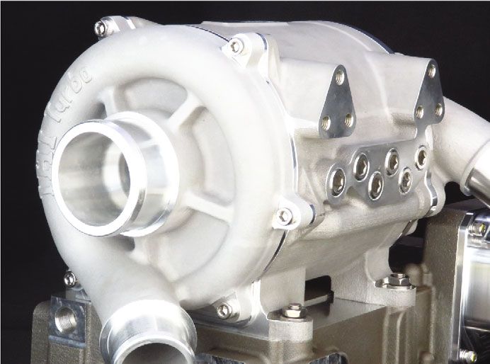
Fuel cells operate quietly as there is no noise from intermit- opment processes considering mass production. Figure 2
tent combustion processes. There are no mechanical gears illustrates the integration of a turbine-assisted electric turbo-
needed, as propulsion is realized by an electric motor. Fuel charger (ETC) in the air supply system and the fuel cell stack
cells have a broad range of applications. In the transporta- system.
International Journal of Rotating Machinery                                                                                                3

                                         Air                Exhaust
                                                                                             Electric power

                                                                        ETC                  Management
                                                 Inverter

                                   Compressor      Motor     Turbine
                                                                                         FC stack

                                                      Inter            Humidifier
                                                      cooler

                             air supply system

        Figure 2: Simplified schematic of fuel cell system indicating the air supply system and the electric turbocharger (ETC).

2. Pressurized Fuel Cells                                                     loads, transient response, and weight and size of the
                                                                              machine. Again, compromising is required to have, depend-
Power density and system efficiency are the most important                      ing on the mission of the fuel cell application, the most
for superior fuel cell systems. The power level is determined                 efficient operation under regular (cycle relevant) long-term
by the product of voltage and current. Both parameters are a                  operation, but also covering short-term requirements as far
function of the internal system pressure. Figure 3 from a                     as possible and meaningful. Thus, compromising in the
principle investigation by Yan et al. [14] shows the effect of                 layout of the thermal turbomachinery can be best weighted
increased pressure on voltage and current for a proton                        if relevant missions, described by transient and steady-state
exchange membrane (PEM) fuel cell, the most common                            power demand, fuel cell stack power, and battery sizing,
for mobile applications. It is to note that, in the present                   are considered. A schematic of the system including fuel cell,
paper, PEM and PEFC (polymer electrolyte fuel cell, com-                      battery, and e-motor is also shown in Figure 2. The FC stack
pare above) are used as synonyms for the same type of fuel                    power needs to cover at least the steady-state (long haul)
cells.                                                                        requirements. In combination with the battery capacity,
    It is obvious that increased pressure increases voltage                   the offered electric power needs to be sufficient to serve
and current output, but pressures above three atmospheres                     requirements also considering short-term demands for
are with limited effect on further power increase. Pressurized                 acceleration and other manoeuvres. The battery can also be
operation will also have a positive effect on the size of the                  charged utilizing energy from regenerative braking. The e-
humidifier and the heat exchanger helping with power vol-                      motor is powerful enough to serve all vehicle manoeuvres.
ume relation of the stack system. Considering the effort for                        It needs to be mentioned that also other technologies can
compression and also for bonding technology to achieve                        be and have been applied to pressurize fuel cells. Super-
stack tightness, the operation pressure of fuel cell stack is                 chargers with their immediate response were used for early
best compromised in the range between 2.5 and 3.0 atmo-                       mobile applications. Their pressure ratio is limited and effi-
spheres [15–18]. Sufficient capability of the compression sys-                  ciency of thermal turbomachinery is superior. Considering
tem for achieving related pressure ratios also considering                    the rather silent e-drive system, the integration of super-
operation under high altitude and/or high temperature con-                    chargers into modern fuel cell propulsion systems will also
ditions is required. In contrast to naturally aspirated sys-                  be challenged by noise issues [10].
tems, actively pressurized fuel cells allow compensation of
low inlet pressure (altitude) and high inlet temperature                      3. Why Apply a Turbine for the Fuel Cell
(hot land) conditions via the compression system. Experi-                        Air Compressor?
ence from turbocharging internal combustion engines with
highly efficient thermal turbomachinery can be utilized.                        For pressurizing the fuel cell stack, a substantial amount of
Modern gasoline Miller engines or state-of-the-art diesel                     energy is needed. The amount of energy is determined by
engines are operated with similar pressure ratios [19]. Com-                  the fluid mass flow, the intended pressure ratio, and the
pare for example Scharf et al. [20]. Experience on sizing and                 compression efficiency. Substantial energy is contained in
optimizing the compression system in terms of map widths,                     the “exhaust gas” of the fuel cell stack, which can be utilized
pressure ratio, and maximum mass flow in the context of                        to assist the compression. In Figure 4(a), the compression
certain power derating under extreme high altitude or tem-                    power for a given mass flow for pressure ratio in a range
perature operating conditions can also be transferred from                    between 1.5 and >3.0 is shown. In the same graph also, the
state-of-the-art turbocharger development. Very high pres-                    available power at the turbine is given. The efficiencies of
sure ratios would lead to the need of more complex two-                       the turbine and the compressor were set constant to the
stage systems. Very high flow rates will lead to rather large                  value of 0.75. Assumptions are taken for the stack outlet or
components with the related effect on rotor dynamics, thrust                   turbine inlet temperature (90°C) as well as the gas
4 International Journal of Rotating Machinery
1000 Fuel cell@80°C, Stoic.: H2/Air = 2/2,
Anode humidity: 100%, cathode humidity: 100%
900
800
700
Voltage (mV)
600
500
400
300
200
100
0 100 200 300 400 500 600 700 800 900 1000 1100 1200
Current density (mA/cm2)
1 atm 3 atm
2 atm 4 atm
Figure 3: Principle effect of air pressure on fuel cell performance under certain assumptions; Yan et al. [14].
18 1,4
mechanical loss, motor eff., inverter eff. : identical
16
1,2
14
Compressor & turbine power (kW)
Compression system efficiency (-)
1
12 Effc = Efft = 0.75 const.
Patm = 101 kPa p3 – p1 0,8
10 Zeta =
Tatm = 25 °C p2 – p1
8 Air flow = 0.1 kg/s
0,6
T3 = 90 °C
6
0,4
4
0,2
2
0 0
1 1,5 2 2,5 3 3,5 1,0 1,5 2 2,5 3 3,5
Compressor pressure ratio (–) Compressor pressure ratio (–)
Compression power With turbine assist, zeta = 0,7
Turbine power (zeta = 0,7) With turbine assist, zeta = 0,5
Turbine power (zeta = 0,5) Without turbine assist
(a) (b)
Figure 4: (a) Power for compression and possible turbine assist and (b) compression system efficiency under different conditions.
composition. The available turbine power also depends on p1 is representing the ambient pressure, p2 represents the
the pressure loss within the stack or the available pressure stack inlet pressure, and p3 represents the turbine inlet pres-
drop across the turbine. Two cases are considered. The sure. The friction, motor, and inverter losses are a function
dashed line shows the turbine power under higher pressure of the rotational speed and therefore the pressure ratio.
drop conditions, whereas the turbine inlet pressure p3 is These losses are considered to be the same for all compres-
calculated from the relation describing ζ: sion systems. Additional assumptions are no condensation
in the turbine and air fuel ratio related to stoichiometric
conditions, lambda, of 1.8.
ðp3 − p1 Þ
ζ= : ð1Þ Obviously, a smaller pressure loss of the stack or higher
ðp2 − p1 Þ available pressure drop at the turbine, represented by higher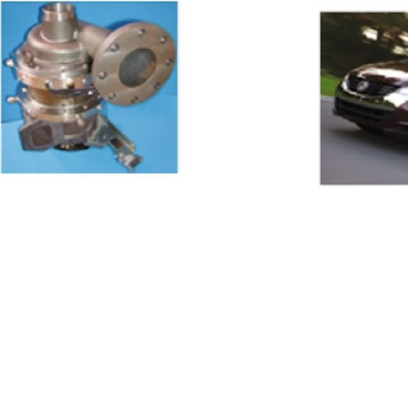
International Journal of Rotating Machinery                                                                                            5

ζ values, supports turbine assist and leads to reduced                   applications. Basic technology development as described in
demand on electrical power for the compression. A com-                   [21] is supporting the product development. Compressor
pressor system efficiency ηsys can be quantified by dividing                and turbine are arranged on one shaft. The rotor is sup-
                                   _ ∗ ΔhÞcompressor by the
the theoretical compression power ðm                                     ported by air bearings to prevent contamination of the fuel
inverter input power Pinverter :                                         cell membrane by hydrocarbons. Any thrust force that is
                                                                         not balanced is compensated by the thrust bearing, which
                                _ ∗ ΔhÞcompressor
                               ðm                                        is of a foil type like the radial bearing. The electric motor
                      ηsys =                      :               ð2Þ    is located between the two radial bearings. Cooling is real-
                                    Pinverter                            ized by water flow to the electric motor, but also by cooling
                                                                         air taken downstream of the heat exchanger that is guided to
    The inverter input power needs to cover the actual                   the air bearings. The attached inverter is supplying the
power for compression ðm     _ ∗ Δh/ηÞcompressor plus the losses         motor with electric power but is also providing the interfaces
from friction Pfriction . Efficiencies η of the e-motor and the            for electrical integration into and communication with the
inverter increase this value, but it is reduced by the power             vehicle infrastructure. It is cooled with water from the low-
that is recuperated by the turbine ðm  _ ∗ Δh ∗ ηÞturbine :              temperature cooling loop. It can be mentioned that the here-
                                                                         with described turbine-assisted electrical turbocharger was
               _ ∗ Δh/ηÞcompressor + Pfriction − ðm
              ðm                                  _ ∗ Δh ∗ ηÞturbine     realized in hardware and was object to substantial validation
Pinverter =                                                          :   and testing. The data utilized for the system comparison is
                              ηe‐motor ∗ ηinverter
                                                                         based on these measurement campaigns. In particular, all
                                                                  ð3Þ    performance data is based on experimental experience.
    Turbine recovery or turbine recuperation R is expressed              4.1. Centrifugal Compressor. Centrifugal compressor tech-
by relating the power that is generated by the turbine to the            nology is utilized for pressurizing the fuel cell. A typical
power that is needed for the air compression:                            compressor map with its characteristics is shown in
                                                                         Figure 6. This is based on experimental results that are
                            ðm_ ∗ Δh ∗ ηÞturbine
                      R=                         :                ð4Þ    obtained with very similar equipment described in [22],
                           ðm_ ∗ Δh/ηÞcompressor                         but with fewer difficulties in considering heat flows. Such
                                                                         kind of technology excels with outstanding efficiency but
    Depending on actual losses in the electronic system and              has operational limits that need to be respected. For lower
the compressor efficiency, this compressor system efficiency                 mass flows, the surge limit needs to be respected. This is a
is by far smaller than unity without turbine assist as is shown          system limit that is also influenced by volumes of neighbour-
in Figure 4(b). If the e-motor is assisted by a turbine, the             ing components [23]. Operation with lower mass flows than
compressor system efficiency increases, since approximately                indicated by the surge line is not possible. The maximum
25% to 30%—in the best matching operation, even higher                   mass flow is limited by choke which is determined by the
assist is possible—of the required compressor power can be               minimum flow area of the compressor stage along the flow
provided by the turbine. Advantageous is that not only the               path. The maximum rotation speed is limited by strength
system efficiency increases but also the available stack output            criteria and rotor dynamics, whereas the loading is domi-
power is increased, since the loss from compression is                   nated by centrifugal stress. The best efficiency and map
reduced by the power from turbine assist. Moreover, the e-               width compromise can be achieved if the best efficiency
motor and inverter size can be reduced. Certainly, a proper              pressure ratio is on a level below 3.0. In the electrical turbo-
integration of the turbine into the system with related piping           charger, the layout of the compressor stage needs to be
needs to be ensured.                                                     adapted to the speed that allows electric operation. There-
    Several technology options can be considered, e.g., two-             fore, the electrically driven compressor comprises a specific
stage compressors with intercooling between the compressor               design differing from standard ICE turbocharger compressor
stages. However, the highest output power and the best effi-               designs. High specific pressure ratios are realized to have the
ciency systems are achieved by applying a turbine to assist              best combination with the electric drive. The number of
the compression. This is even more valid as low-pressure                 blades is increased, and backward curvature at the blade out-
drop stacks are utilized. The discussion if the turbine needs            let is rather low. Mass flow adaptation can be achieved by
to be with variability is a lively one. Results from principal           scaling or trimming of the compressor stage [23]. Scaling is
investigations to assess these technology options will be                meant as a geometrical change with a constant factor in all
given later in this paper. In the following section, a brief             three spatial dimensions, whereas certain tolerance and min-
description of the turbine-assisted electrical turbocharger              imum dimensional limits need to be respected. Trimming is
for fuel cell application is given.                                      understood in a way that the compressor wheel tip contour
                                                                         is modified while the basic compressor stage geometry is
4. Turbine-Assisted Electrical Turbocharger for                          kept unchanged. Figure 6 shows a comparison of maps that
   Fuel Cell Applications                                                are scaled, respectively, trimmed, to 85% of the original mass
                                                                         flow capacity and compared to a base map. Thereby, the fac-
Figure 5 shows the schematic of the components assembling                tor for the map modification determines the change of max-
the turbine-assisted electrical turbocharger for fuel cell               imum flow area and is therefore proportional to the change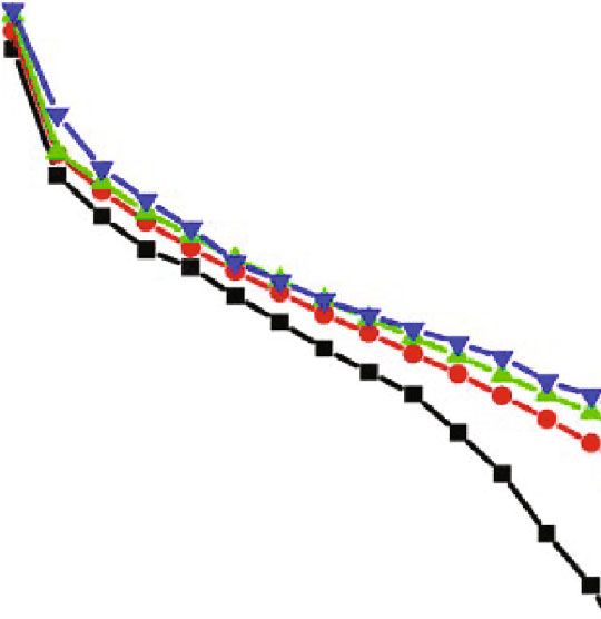
6 International Journal of Rotating Machinery
Heat
Fuel cell stack
Low temperature exchanger
coolant
Wet air
Compressor
Turbine
Fresh
Bearing
Bearing
air Motor
CAN
Inverter
HV-DC
Electric turbocharger
Low temperature coolant
Figure 5: Schematic of components of electrical turbocharger.
3.4 85% scale Base 3.4 85% trim Base
Constant Constant
3.2 Rotation 3.2 Rotation
Speed Speed
3.0 3.0 C
B
2.8 2.8 A
Choke (scale)
Choke (scale)
Choke (base)
Choke (base)
2.6 2.6
Pressure ratio (tt) -
Pressure ratio (tt) -
Exemplary trim
)
Contours [19]
se
2.4 2.4 )
se
ba
ba
e(
e(
2.2 2.2
rg
rg
Su
Speed Speed
Su
le)
Speed Speed =
le)
2.0 2.0
sca
(Scale) > (Base) (Trim) (Base)
sca
e(
e(
rg
1.8 1.8
rg
Su
Su
1.6 1.6
1.4 1.4
Increase of Increase of
1.2 1.2
Rotation speed Rotation speed
1.0 1.0
0 1 2 3 4 5 6 7 8 9 10 11 12 13 14 15 0 1 2 3 4 5 6 7 8 9 10 11 12 13 14 15
Volumetric flow rate Q293 m3/min Volumetric flow rate Q293 m3/min
(a) (b)
Figure 6: Comparison of compressor maps: (a) base map vs. scaled map; (b) base map vs. trimmed map.
in mass flow. At first sight, the scaled or trimmed maps look ciency might decrease due to resulting small blade heights
very similar. Dominant difference is the change of rotational and therefore changed blade loading. Stronger trim might
speed for the scaled version. Scaling down requires higher suffer from larger relative fillets and larger relative tip clear-
rotational speed for achieving the target pressure ratio due ance due to reduced blade height. Trimming up needs also
to a reduced compressor outlet diameter. In the trimmed care to not sacrifice efficiency and stability at low flow rates
version, the target pressure ratio does not change the due to increased curvature at the shroud and larger blade
required rotational speed, which is advantageous in combi- heights in the inducer area. Also, stress limits need to be
nation with an electric drive. Neglecting minor tip clearance carefully considered if the compressor is trimmed up.
effects, scaling in a limited range conserves the efficiency Since stress loading needs to be kept below the material
level of a compressor family. Having an optimized compres- limits, larger components will allow only lower rotational
sor as a base, trimming needs to be done with care since effi- speed. This has an effect on the layout of the motor; the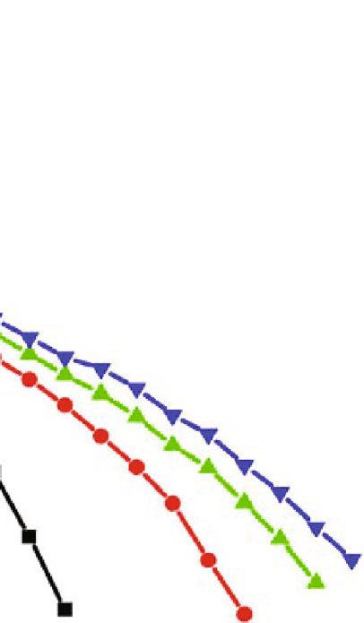
International Journal of Rotating Machinery                                                                                     7

inertia of the components will increase with a negative effect     defines the peak motor torque requested for starting up the
on transient response, whereas in an electrified turbocharger      fuel cell system in a sufficient short period of time, assuming
this can commonly be compensated by the e-motor. Also,            always that the electric turbocharger can be served with suf-
the thrust capability of the bearings needs to sufficiently         ficient electric energy.
account for this. The principle relation is that larger compo-
nent diameters will cause higher thrust forces. The compres-      4.3. Oil-Free Air Bearings. Contaminants from air supply
sor has stronger influence on thrust than the turbine due to       components, like structural materials, lubricants, adhesives,
the higher acting pressures and diameters, respectively, pres-    sealants, and hoses, have been shown to affect the perfor-
surized surface areas. Customizing map characteristics is         mance and durability of fuel cells—in particular the highly
possible by adjustment of specific speed and specific work          sensitive membranes. Therefore, the charging system which
coefficient through modifications of blade profile and blade          increases the pressure and therefore the power density of
height as well as diffuser and volute design [24]. Vaned dif-      the stacks needs to be oil-free. Bump foil air bearings have
fusers offer the possibility of achieving higher pressure ratios   been selected to support the rotor of the investigated fuel cell
with some adverse impact on map width [19, 23]. State-of-         turbocharger in radial and axial direction. The air bearings
the-art optimization methods [25] with multiobjective opti-       allow stop-start operation and therefore a complete shut-
mization targets are utilized to realize the best efficiency base   down of the system in the absence of any energy demand.
compressor designs. Scaling and trimming allow adaptation         The coated and shaped foils provide sufficient robustness
to the application-specific requirements of a fuel cell system.    for multiple events under mixed friction conditions. The
     In a later chapter, the paper at hand addresses the possi-   gas bearings need to offer excellent damping behaviour
bility of two-stage compression systems and gives an assess-      under high-speed operation, which is mandatory especially
ment in comparison to the one-stage system.                       in vehicular applications [26]. :For predicting bearing loads
                                                                  and the displacement characteristic of the rotor, a dedicated
4.2. Electric Motor and Power Electronics. The electric motor     simulation procedure was developed.
is of a surface permanent magnet type. The design of the              Utilizing this procedure, limits of the rotor displace-
mechanical reinforcement of the rotating permanent magnet         ments under vibrations could be defined. For safe and dura-
is challenging, and the choice of suitable material for the       ble long-term operation, the bearings are cooled. The
armour ring is decisive. It is considering the strength limits    minimized pressure losses in the cooling passages were
of turbine, compressor, and rotor shaft. The allowable maxi-      adjusted for the best distribution of the cooling air in the
mum rotational speed of the turbocharger is respecting these.     centre section and the electric motor.
The rare earth magnet is with high magnetic energy density.
The synchronous electric motor has two poles. The windings        4.4. Radial Turbine. Radial flow turbine technology is uti-
are realized to maximize the amount of copper in the avail-       lized for reducing the need of electric motor power to drive
able design space. It comprises the best speed stability and      the compressor to pressurize the fuel cell. A typical fixed
low variation resulting in favourable low noise behaviour.        geometry turbine (FGT) map with its characteristics is
    Features of power electronics and electric motor interac-     shown in Figure 7. This is based on experimental results that
tion are vector modulation and sensor less control. The           are obtained with very similar equipment described in [22],
switching frequency is on a sufficiently high level to allow        but due to the low temperature level compared to conven-
control for rotational speeds well above 100 krpm. The coil       tional ICE turbochargers with electric heating of the turbine
temperature is monitored for ensuring efficient and safe            inlet mass flow. The lines give the relationship between mass
long-term operation. The inverter is attached to the motor        flow and pressure ratio. The scaled map is showing a
housing for avoiding EMC issues which is increasingly diffi-        reduced mass flow of 85% compared to a base map. Thereby,
cult to contain with increasing distance between motor and        the factor for the map modification determines the change of
inverter. Reliable operation also needs to consider environ-      maximum flow area and is therefore proportional to the
mental influences. Avoiding humidity and sealing against           change in mass flow. The speed of the scaled turbine wheel
water are indispensable. Therefore, sealing of the connector      is higher due to the lower turbine inlet diameter.
interface between motor and inverter was introduced. In this          Available assist power is closely linked to the pressure
regard, also the plug and related connector were enhanced.        loss over the fuel cell stack and to the composition of the
Special care was taken on waterproof interfaces integrated        gas at the inlet. The best efficiency operation for pressure
in the plug connector, which is installed at the motor side.      ratio between 2.0 and 3.5 can be expected, but depends on
The electronic inverter is integrated into the turbocharger.      the specific layout of the turbine stage. Under typical pres-
    The power of the electric motor is defined via the power       sure and temperature conditions in fuel cells, fixed geometry
request for compression. Considering the recuperation             turbines can generate up to 40% of the required power for
power from the turbine allows a layout of a reduced electric      compression, which is shown in detail below. Mass flow
motor capability compared to compression systems without          adaptation can be achieved by scaling of the turbine stage
turbine assist. This improves the compactness of the design,      as shown above, respecting rotor dynamics and bearing load
but also reduces the inertia of the rotor. The acceleration       capacity. Customizing of the turbine map characteristics is
behaviour of the machine is improved. This also is one            possible by adjustment of specific speed and specific work
important mode of operation that requires low rotor inertia       coefficient by stator (volute and ring channel) design as well
and high efficiency of the turbomachinery. This mode                as modifications of blade profile and blade height as well as
8                                                                                                                International Journal of Rotating Machinery

                  1.8                                          Increase of                       efficiency is the most relevant. As described earlier, the com-
                              85% scale    Base
                                                               rotation speed                    pression system efficiency is calculated from the compres-
                                                                                      Speed      sion power related to the needed inverter power. It also
                  1.6
                                                                                      (base)
                                                                                                 has to be noted that the inlet temperature of the humidifier
kg/s K0.5 Pa–1

                                                                                       <
                  1.4                                                                 Speed      needs to stay below 100°C. Therefore, an aftercooler needs
                                                                                      (scale)    to be considered for both compression systems. The inter-
                  1.2                                                                            cooling in the two-stage system will have an effect on the
                                                                                                 total cooling power, but also the cooling power of the after-
–5

                  1.0                                                                            cooler. Therefore, this is a parameter that is also considered.
                                                                                                 Based on the cooling power, a rough estimation of sizes of
                  0.8                                                                            the heat exchangers is elaborated.
                                                                                                     The investigations assume a typical pressure loss of the
                  0.6
                                                                                                 intake air filter. For the estimation of the size of the heat
                  0.4
                                                                                                 exchangers, the surface area for heat transfer is used as an indi-
                                                                                                 cator. The temperature of the cooling medium is assumed to be
                  0.2                                                                            318 K. Since the focus is on comparing the two systems, param-
                                                                                                 eters like inverter and motor losses were assumed to be
                  0.0                                                                            unchanged for both systems and for simplicity set to unity. This
                        1.0     1.4       1.8      2.2      2.6        3.0      3.4        3.8   results in rather high efficiencies, but comparison under the
                                                  Pressure ratio (tt) -                          mentioned assumptions is possible without any restrictions.
                                                                                                     Figure 9 shows results of the zero-dimensional study. For
                 Figure 7: Comparison of turbine map: scaled vs. base map.
                                                                                                 the two-stage system, a split of 1.10 in single pressure ratios
                                                                                                 of the two stages was investigated. This split is based on expe-
diffuser geometry. Decisive here is the suitable choice of                                        rience with two-stage turbocharging systems and respects
degree of reaction for the design point and efficiency charac-                                     that the system in this study is assembled on one shaft. Both
teristics under varying operating conditions. Since fuel cells                                   compressors need to comply with the same rotational speed.
are operated under varying but steady-state conditions, tur-                                     The low-pressure compressor is larger in diameter compared
bine definition for fuel cells is simpler than for turbochargers                                  to the high-pressure compressor and therefore exhibits a
for internal combustion engines. Still, all experience from                                      higher tip speed which is relevant for the aerodynamic lay-
turbocharger turbine design as well as from operation of                                         out. This means that for the best efficiency layouts, the pres-
centrifugal machines under condensation conditions can be                                        sure ratio for the low-pressure stage should be higher than
overtaken [27–31].                                                                               that for the high-pressure stage which comprises the lower
     Condensation and interaction with eventual droplets in                                      tip speed. The map width and especially the surge limit
the exhaust need to be accounted for in designing turbines                                       restrict the selection of the split of the pressure ratios to
for fuel cell applications. Based on experience with droplets                                    values lower than 1.15. More detailed general information
from condensation in compressors [29] and from turbine                                           on two-stage charging systems can be found in [19].
applications in fuel cells, droplets at the intake of the turbine                                    The pressure ratio of the single-stage vs. the total pres-
should be avoided by installation of a droplet separator.                                        sure ratio is shown on the graph in Figure 9(a). Figure 9(c)
Nevertheless, substantial experimental effort was taken to                                        shows the temperature after compression. The effect of
quantify the turbine resistance against droplets, since drop-                                    intercooling, in this investigation down to 318 K, is clearly
lets cannot necessarily be avoided for all operating condi-                                      visible, but the results prove that aftercooling is required
tions. Condensation from the change of state of the humid                                        for both systems. In Figure 9(c), the required temperature
air during expansion in the turbine can be recognized, but                                       range at the humidifier inlet is indicated. The broken line
does not harm turbine durability. Efficiency effects from                                           describing the single-stage system indicates that operation
condensation are known and can be considered [30, 31]. In                                        for very high pressure ratio needs to be limited. For a pres-
any case, single-stage turbines are less affected than multi-                                     sure ratio of 3.5, the difference in outlet temperature is
stage turbines. Condensation effects are not considered in                                        approximately 60 K. In Figure 9(b), the compression power
the given turbine maps.                                                                          is compared. The broken, dotted line shows the power
     In a later chapter, the paper at hand addresses the possi-                                  request for the single-stage compression system. The request
bility of a variable turbine system (VGS) and gives an assess-                                   for compression power for the two-stage system is reduced
ment compared to a fixed geometry turbine.                                                        by the effect from intercooling, whereas this effect is only
                                                                                                 visible for total pressure ratios above 2.2 with related higher
5. Two-Stage Compressor with Intercooler vs.                                                     compression temperatures (A). Much stronger reduction of
   Turbine-Assisted Electric Turbocharger                                                        compression power is achieved by assisting the compressor
                                                                                                 with the turbine (B). In consequence, the compressor system
Figure 8 shows the investigated arrangements. A single-stage                                     efficiency of the turbine-assisted single-stage system is nota-
compression system with a turbine for recuperation is com-                                       bly higher. This is shown in Figure 9(d).
pared with a two-stage compression system with intercooler.                                          The required cooling power is given in Figure 10. As
For comparing the two concepts, the compression system                                           expected, the total cooling power for the two-stage system
International Journal of Rotating Machinery 9
Coolant
Single-stage system
After
cooler
Air filter C
Humidifier
Ambient
FC stack
e-
motor
T
(a)
Coolant
Two-stage +
inter cooler system Inter
Coolant
cooler
After
cooler
e-motor
Humidifier
Ambient
Air filter C C
FC stack
(b)
Figure 8: Schematic on compressor system arrangements: (a) turbine-assisted single-stage compressor; (b) two-stage compressor with
intercooler.
is reduced. The amount of heat that is transferred in the humidifier inlet temperature. Such configuration needs to
intercooler is also shown in Figure 10. Assuming that similar have most compression in the first compressor stage, and
types of heat exchangers comprise a nearly constant heat therefore, the intercooler size will have to have nearly twice
transfer rate h, the area for heat transfer A is defined by the size of the single-stage compression aftercooler with
the heat flow Q_ and the given temperature difference ΔT the related packaging disadvantages. Moreover, this extreme
across the heat exchanger. split of compression ratio will not allow the best aerody-
namic performance as described above.
There is also the choice of turbine type. Based on
Q_
h= = const: ð5Þ decades of turbomachinery development, IHI has vast expe-
A ∗ ΔT rience with turbines and their various inlet housing or inlet
stator configurations [28, 32]. Inlet variability is an option
With this simple approach, the relative size and weight to adapt the turbine mass flow capacity to instantaneous
of the heat exchangers can be estimated, since in needs of the fuel cell system, if operated under variable
Figure 9(c) the temperatures are given and Figure 10 dis- conditions.
plays the cooling power or heat flows. For a pressure ratio
of 2.8 and the split of pressure ratios of 1.10, the size of 6. Variable Turbine vs. Fixed Geometry Turbine
the two-stage aftercooler is then about 69% of the size of
the single-stage system, whereas the single-stage system Once the geometry of a compressor stage is defined, the
aftercooler size was defined as 100%. But the two-stage sys- rotating speed of a radial compressor is determined from
tem needs additionally an intercooler with a size that is the mass flow and the requested pressure ratio. Figure 11
about 86% the size of the aftercooler of the single-stage sys- shows a typical map of a centrifugal compressor with its
tem. In total, this offers a package advantage for the single- limits on the maximum flow (choke) and minimum flow
stage system. This advantage is less pronounced with higher (surge). Lines of constant speed and efficiency islands are
pressure ratios and therefore higher total cooling demand, indicated. For further discussion, the investigated operating
but in any case, the two-stage system requires two cooling points (OP) are indicated by coloured full circles. The grey
devices with the related implications for installation. circles in the compressor map in Figure 11(a) give the
An extreme configuration might allow to eliminate the compressor operation. The blue coloured circles display
aftercooler while still keeping the temperature limit of the the turbine operation in Figure 11(b). It is certainly most
humidifier after compression by selecting an appropriate desirable to operate the compressor in the range of its best
split of compression ratios. The target is here that the air efficiency. For having the best system efficiency, the aerody-
temperature after the second compression is lower than the namicist will choose the geometric parameters of the turbine10 International Journal of Rotating Machinery
2,2 40,0
Single-stage pressure ratio (LP, HP) (-)
35,0 A
2,0 B
Compression power (kW)
30,0
1,8
25,0
1,6 20,0
15,0
1,4
10,0
1,2 5,0
1,0 0,0
1,0 1,5 2,0 2,5 3,0 3,5 4,0 1,0 1,5 2,0 2,5 3,0 3,5 4,0
Total pressure ratio (-) Total pressure ratio (-)
Split 1.10 LP Single-stage, no assist
Split 1.10 HP Single-stage, with assist
Two-stage, with inter-cooler
(a) (b)
500 1,4
480
Temperature at air supply exit (K)
1,2
460
440 1,0
420
400 0,8
380 0,6
360
340 inlet temp. limit 0,4
320
Inter cooler temperature 0,2
300
280 0,0
1,0 1,5 2,0 2,5 3,0 3,5 4,0 1,0 1,5 2,0 2,5 3,0 3,5 4,0
Total pressure ratio (-) Total pressure ratio (-)
Single-stage Single-stage, with assist
Two-stage Two-stage, with inter-cooler
(c) (d)
Figure 9: Comparison of single-stage with turbine assist and two-stage with intercooling: (a) single-stage pressure ratio vs. total pressure
ratio; (b) power for compression with and without assist; (c) temperature after compression; (d) system efficiency.
stage in a way to ensure optimum efficiency along the p3
requested characteristic of the machine. _ turbine = f m
m _ compressor ; ; T3 ; n ; λ : ð7bÞ
p1
In this example, operation in OP “B” requests best
system efficiency. Therefore, the fixed geometry turbine is Equation (1) defining ζ gives the relation between stack
designed to “match” with the compressor operation in “B.” inlet pressure p2 and turbine inlet pressure p3 considering
This matching can be described by conditions that have to related losses. T 1 describes the inlet temperature of the com-
be met. Since the turbine and the compressor are mounted pressor, and T 3 is the temperature at turbine inlet, which is
on one shaft, it is obvious that the rotational speed n of com- determined by the stack inlet temperature after cooling and
pressor and turbine is the same: the heat release in the stack. λ is the air fuel ratio, namely,
the ratio between hydrogen and oxygen, which also impacts
the turbine mass flow. In this study, T 1 = 298 K, T 3 = 343 K,
ncompressor = nturbine = n: ð6Þ
and ζ = 0:7 for OP “H” and a constant air fuel ratio λ = 1:8
are applied as typical values. Based on the component char-
Moreover, the pressure ratio and mass flow characteris- acteristics shown in the maps in Figure 11 and the require-
tics of these two components need to match considering ments given in Equations (1), (6) and (7), the matching
the properties of the fuel cell stack and installations: operation for compressor and turbine can be determined
as illustrated with the bold, broken line. Thus, the best effi-
ciency operation along this line does not require any vari-
p2
_ compressor = f
m ; T1 ; n , ð7aÞ ability of the turbine, but can be realized with a fixed
p1 geometry turbine. OP “H” can offer pressure ratio and massInternational Journal of Rotating Machinery 11
30,0
Cooling @ inter & after cooler (kW)
25,0
20,0
15,0
10,0
5,0
0,0
1,0 1,5 2,0 2,5 3,0 3,5 4,0
–5,0 Heating
Total pressure ratio (-)
Total cooling: single stage
Total cooling: two-stage
Inter-cooling: two-stage
Figure 10: Total cooling power at inter- and aftercooler vs. total pressure ratio.
Compressor Fixed geometry turbine
3.6
2.0
3.4 L2
Increase of
1.8
3.2 Constant rotation speed
B2
Mass Flow Parameter x10^-5 kg/s K^0.5 Pa^-1
efficiency
3.0 1.6
2.8 1.4
H
Pressure Ratio (tt) -
H1 H B H1
2.6 B2
1.2
2.4 L H1
B B2 1.0 L1
2.2
L2 L1
2.0 0.8
1.8 L1 L L2 0.6
1.6
0.4
1.4
Increase of 0.2
1.2
rotation speed
1.0 0.0
0 2 4 6 8 10 12 14 1.0 1.4 1.8 2.2 2.6 3.0
Volumetric flow rate Q293 m3/min Pressure Ratio (tt) -
(a) (b)
x Compressor operation
X Stack outlet conditions
X Turbine operating conditions
Matching operation C+T
By pass flow
Flow restrictor
Figure 11: Compressor and turbine characteristics and investigated operating points (OP); (a) compressor; (b) fixed geometry turbine; OP L
+B+H: matching with FGT; OP H1+L1: operation close to surge; OP B2+L2: operation closer to choke.12 International Journal of Rotating Machinery
Table 1: Mass flow (MFP), pressure ratio (PR), efficiency (Efft), and turbine recuperation rate (R) for different operating conditions (OP) of
a fixed geometry turbine (FGT) and a variable turbine (VGS).
OP H B L L1 H1 L2 B2
PR — 2.21 1.90 1.51 1.57 2.28 1.37 1.81
Stack
MFP × 10−5 (kg/s) K0.5 Pa−1 1.38 1.34 1.17 0.90 1.15 1.93 1.72
PR — 2.21 1.90 1.51 1.38 1.97 1.37 1.81
MFP × 10 (kg/s) K0.5 Pa−1
−5 1.38 1.34 1.17 1.02 1.33 0.91 1.27
Fixed geometry turbine
Efft — 0.75 0.75 0.74 0.68 0.71 0.52 0.70
R % 37.0% 38.6% 39.3% 28.0% 30.7% 9.0% 23.4%
PR — 2.21 1.90 1.51 1.57 2.28 1.37 1.81
MFP × 10−5 (kg/s) K0.5 Pa−1 1.38 1.34 1.18 0.90 1.15 1.93 1.72
VGS turbine
Efft — 0.73 0.73 0.72 0.69 0.72 0.46 0.66
R % 36.3% 37.8% 38.5% 38.4% 36.6% 16.8% 30.0%
flow margin allowing operation under high altitude condi- mass flow parameter, and efficiency (Efft) as well as the recu-
tions without the need for derating of the stack power. The peration rate (R) according to Equation (4) are given for
given operation “H” in this case allows inlet conditions at both technologies. For the FGT, the (shift in) turbine opera-
approximately 1500 m altitude, and the compressor is still tion is illustrated in Figure 11(b).
delivering the same pressure at the stack inlet as for opera- It can be noted that for most of the OPs, the difference is
tion “B” under normal sea level conditions. OP “L” repre- small. For OP “H,” “B,” and “L” under the best recovery con-
sents operation under low load. As soon as the operation ditions, the generated assist power of the fixed geometry tur-
deviates from this best efficiency operation, the fixed geom- bine is higher than that for the variable turbine, since some
etry turbine will not be operated under its best conditions. gap losses in the stator can be avoided in a design of a
OP “L2” and “B2” were selected to show the effect when a FGT and therefore efficiency is higher. In OP “L,” the rela-
bypass is needed and a portion of the exhaust gas energy tive recuperation is the highest due to the reduced pressure
cannot be utilized. “L2” comprises the same pressure ratio loss in the stack for low flow. The FGT reaches almost 40%.
as “L” and the same flow as “B.” “B2” has the same pressure For OP “L1” and “H1,” a variable turbine shows an
ratio as “B” and the same flow as “H.” OP “L1” and “H1” advantage in turbine output power due to the higher usable
require reducing the turbine pressure ratio to match the pressure ratio and caused by this also better stage efficiency.
pressure ratio—mass flow characteristics of the given tur- The level of recovery for OP “L1” and “H1” with reduced
bine. “L1” comprises the same pressure ratio as “L.” “H1” mass flow compared to optimal operation is between 28%
has the same pressure ratio as “H.” This operation is illus- and 38%. Recuperation is higher for the variable turbine,
trated in Figure 11. Figure 11(a) shows the characteristics but the absolute power level is low. For OP “L1,” the needed
of a fixed geometry turbine that is sized to allow the best compressor power is only 6.3 kW, compared to 25.4 kW for
operation under conditions “L,” “B,” and “H.” It also shows OP “H.” Respectively, the recuperation power for OP “L1” is
how operation in “H1,” “B2,” “L1,” and “L2” needs to shift to only 2.4 kW with the variable turbine and 1.8 kW for the
match with the turbine design. FGT, a difference of 0.6 kW in absolute values. For OP
Assuming typical fuel cell operation with related pres- “B2” and “L2,” the efficiency of the variable turbine is
sure loss over the stack and gas conditions, the power from reduced, but it can utilize the complete mass flow provided
turbine assist for a fixed geometry turbine (FGT) and a var- from the fuel cell stack, leading to recuperation advantage
iable geometry system (VGS) was compared. For both tur- for the variable turbine. The recovery rate for OP “B2” and
bine types, the same compressor operation providing the “L2” with increased mass flow compared to optimal recuper-
pressurized inlet flow for the fuel cell stack, namely, com- ation is in the maximum 30%. For OP “B2,” the needed
pressor pressure ratio, volume flow, and rotating speed, compressor power is 22.1 kW. The recuperation power for
was assumed. Pressure losses from the air inlet filter were OP “B2” is 6.6 kW with the variable turbine and 5.2 kW for
neglected since this is no differentiator for comparing tur- the FGT, a difference of again 0.6 kW in absolute values.
bine operation. Also, the pressure losses in the exhaust pip- For “L2,” the difference in recuperation power between the
ing after the turbine were neglected, since there is minor VGS and the FGT is 1.0 kW.
influence on actual turbine operation. In Table 1, the param- Based on this investigation and targeting for the least
eters of the seven operating points (OP) defined by the design complexity, a fixed geometry turbine is considered
potential turbine pressure ratio (PR) offered downstream suitable and appropriate for assisting compressors for fuel
of the stack and the related mass flow parameters (MFP) cell systems. For operation in the area of OP “L2” and
are listed. The table summarizes the results from this study “B2,” with higher mass flow than for the best efficiency oper-
comparing the two turbine types. Turbine pressure ratio, ation, a simple bypass is an appropriate option. MidflowInternational Journal of Rotating Machinery 13
tems. The electronic inverter is integrated into the
turbocharger as can be seen in Figure 12.
The oil-free turbocharger for fuel cell applications is pro-
viding the latest charging technology to serve emission-free
propulsion systems. It is designed to allow scaling for appli-
cation to different power level fuel cell systems. Multiple
compression systems with turbine recovery are also an
option for application to higher power-sized fuel cell sys-
tems. Hence, this technology is suited to support the
achievement of indispensable sustainable development goals
as requested by modern society.
This paper can serve as a base for allowing pressurized
fuel cell system optimization utilizing existing experience
with turbocharging systems. In future developments, the
Figure 12: Photograph of the electric compression system with electric turbocharger needs to be treated as an integrated
turbine assist and attached inverter. component of the fuel cell air supply. Optimizing the com-
plete fuel cell system considering its thermal management,
range operation of the turbine-assisted turbocharger at the the properties of the centrifugal turbomachinery, but also
best efficiency is the most beneficial to reduce the electricity the electronics will allow even better system power density,
consumption. Such operation can be well served by a FGT. efficiency, and compactness.
7. Summary Data Availability
The power density of fuel cells substantially increases if the The data used to support the findings of this study are
system is pressurized. However, contaminants from fuel cell included within the article.
system components like structural materials, lubricants,
adhesives, sealants, and hoses have been shown to affect
the performance and durability of fuel cells. Therefore, the Conflicts of Interest
charging system that increases the pressure and hence the
The authors declare that there is no conflict of interest
power density of the stacks inevitably needs to be oil-free.
regarding the publication of this paper.
For this reason, gas bearings are applied to support the
rotor of a fuel cell turbocharger. It furthermore comprises
a turbine, a compressor, and, on the same shaft, an electric Acknowledgments
motor. The turbine utilizes the exhaust energy of the stack
to support the compressor and hence lowers the required The authors are grateful to IHI Corporation for funding this
electric power of the air supply system. The study at hand work and for the permission to publish.
demonstrates that such a system is more efficient compared
to a two-stage compressor system with intercooler. The tur- References
bine can produce more than 30% of the needed compressor
power. Hence, it substantially increases the system efficiency. [1] U. Kramer, D. Göricke, and R. Thee, “Energy paths for road
The turbine is designed to reliably operate with the best effi- transport in the future,” MTZ worldwide, vol. 80, no. 5,
ciency in a humid air environment: a certain amount of pp. 18–25, 2019.
droplets and vapour can be tolerated. It was shown that a [2] U. Kramer, F. Ortloff, and S. Stollenwerk, Defossilisierung des
fixed geometry turbine design delivers optimal recuperation Transportsektors: Optionen und Voraussetzungen in Deutsch-
power. The compressor is of a low specific speed type with a land, Band 586 von Forschungsvereinigung Verbrennungskraft-
maschinen R, Verlag FVV, 2018.
vaneless diffuser. It is optimized for operating conditions in
a fuel cell system regarding specified airflow and pressure [3] G. Hutchings, M. Davidson, P. Atkins et al., Sustainable Syn-
thetic Carbon Based Fuels for Transport: Policy Briefing, The
ratio, which is typically in the range of 3.0. Accordingly, such
Royal Society, 2019, ISBN: 978-1-78252-422-9.
electrified turbocharger enables higher power density fuel
[4] Y. Ruf, M. Baum, T. Zorn, A. Menzel, and J. Rehberger, Fuel
cell systems. The gas bearings allow start-stop operation
Cells Hydrogen Trucks- Heavy-Duty´s High Performance Green
and therefore a complete shutdown of the system, in the Solution, R. Berger, Ed., Fuel Cells and Hydrogen 2 Joint
absence of any energy demand. The coated and shaped foils Undertaking (FCH 2 JU), 2020, ISBN: 978-92-9246-347-2.
provide sufficient robustness for multiple events under [5] Y. Ruf, T. Zorn, P. A. De Neve et al., Use of Fuel Cells and
mixed friction conditions. The gas bearings offer excellent Hydrogen in the Railway Environment, R. Berger, Ed., Fuel
damping behaviour under high-speed operation, which is Cells and Hydrogen Joint Undertaking (FCH JU) and the
mandatory in vehicular applications. Moreover, the electri- Shift2Rail Joint Undertaking (S2R JU), 2019, ISBN 978-92-
fied turbocharger system provides direct customer benefit 95215-11-5.
since it is superior in noise behaviour compared to super- [6] Hydrogen-Powered Aviation, A Fact-Based Study of Hydrogen
charger systems that served to pressurize earlier fuel cell sys- Technology, Economics, and Climate Impact by 2050,14 International Journal of Rotating Machinery
McKinsey & Company, Clean Sky 2 JU and Fuel Cells and [22] H. Mai and H. Bolz, “Validierung von Turboladerkennfeldern
Hydrogen 2 Joint Undertakings, 2020, ISBN 978-92-9246- auf Heissgasprüfständen,” in ATZ Extra – Prüfstände und
342-7. Simulationen für Antriebe, pp. 54–58, 2015.
[7] Bundesministerium für Wirtschaft und Energie (BMWi), Die [23] M. Casey and C. Robinson, Radial Flow Turbocompressors-
Nationale Wasserstoffstrategie, Berlin, 2020. Design, Analysis, and Application, Cambridge University
[8] F. Gérard, L. van Nuffel, T. Smit et al., Opportunities for Hydro- Press, 2021, ISBN 978-1-108-41667-2.
gen Energy Technologies considering the National Energy & [24] P. Harley, S. Spence, D. Filsinger, M. Dietrich, and J. Early,
Climate Plans, Trinomics & LBST, Fuel Cells and Hydrogen “Experimental and numerical benchmarking of an improved
2 Joint Undertaking, 2020, Reference number: FCH / OP / meanline modelling method for automotive turbocharger cen-
Contract 234. trifugal compressors,” in ASME TURBOEXPO 2015: Turbine
[9] IHI Corporation, IHI integrated report, 2020, https://www.ihi Technical Conference and Expositition, Montreal, Canada,
.co.jp/csr/english/download01/pdf/integrated2020_E_all.pdf. 2015.
[10] C. Mohrdieck and S. Dehn, “The intelligent fuel cell plug-in [25] A. Starke, T. Bamba, D. Filsinger, and P. Harley, “An auto-
hybrid drive system of the Mercedes-Benz GLC F-cell,” MTZ matic optimisation of a centrifugal compressor for improved
worldwide, vol. 80, no. 1, pp. 30–37, 2019. performance at near surge operation,” in Proceedings of the
International Gas Turbine Congress, pp. 495–501, Tokyo,
[11] M. Venturi, C. Mohrdieck, and J. Friedrich, “Mercedes-Benz
2015.
B-Class Fuel Cell: the world largest hydrogen vehicle fuel cell
fleet experience,” in 2013 World Electric Vehicle Symposium [26] A. Furuno and N. Omori, Design and performance evaluation
and Exhibition (EVS27), Barcelona, Spain, 2013. of gas foil bearing for turbo blower, Japan Society of Mechanical
Engineers, 2016.
[12] K. Onda, T. Osaka, Y. Ogawa et al., Molten Carbonate Fuel Cell
Power Generation Technology Development, Evaluation [27] B. Lüddecke, D. Filsinger, and J. Ehrhard, “On mixed flow tur-
Report, Incorporated Administrative Agency New Energy bines for automotive turbocharger applications,” International
and Industrial Technology Development Organization, 2005. Journal of rotating machinery, vol. 2012, Article ID 589720, 14
pages, 2012.
[13] B. Blunier and A. Miraoui, “Air management in PEM fuel cells:
state-of-the-art and prospectives,” in International Aegean [28] J. Walkingshaw, G. Iosifidis, T. Scheuermann, D. Filsinger, and
Conference on Electrical Machines and Power Electronics, Bod- N. Ikeya, “A comparison of a mono, twin and double scroll
rum, Turkey, 2007. turbine for automotive applications,” in Proceedings of ASME
Turbo Expo, Montreal, Canada, 2015.
[14] Q. Yan, H. Toghiani, and H. Causey, “Steady state and
dynamic performance of proton exchange membrane fuel cells [29] D. Talmon-Gros, B. Huurdeman, B. Lüddecke, and
(PEMFCs) under various operating conditions and load D. Filsinger, “Analysis of components for low-pressure
changes,” Journal of Power Sources, vol. 161, no. 1, pp. 492– exhaust gas recirculation,” MTZ-Motortechnische Zeitschrift,
502, 2006. vol. 75, no. 3, pp. 44–49, 2014.
[15] B. Blunier and A. Miraoui, “Proton exchange membrane fuel [30] S. Schuster, D. Brillert, and F.-K. Benra, “Condensation in
cell air management in automotive applications,” Journal of radial turbines—part I: mathematical modeling,” Journal of
Fuel Cell Science and Technology, vol. 7, no. 4, 2010. Turbomachinery, vol. 140, no. 10, p. 101001, 2018.
[16] A. C. Rojas, G. L. Lopez, J. F. Gomez-Aguilar, V. M. Alvarado, [31] S. Schuster, D. Brillert, and F.-K. Benra, “Condensation in
and C. L. S. Torres, “Control of the air supply subsystem in a radial turbines—part II: application of the mathematical
PEMFC with balance of plant simulation,” Sustainability, model to a radial turbine series,” Journal of Turbomachinery,
vol. 9, no. 1, p. 73, 2017. vol. 140, no. 10, p. 101002, 2018.
[17] H. Liu, P. Li, A. Hartz, and K. Wang, “Effects of geometry/di- [32] M. Rode, T. Suzuki, G. Iosifidis et al., “Boosting the future with
mensions of gas flow channels and operating conditions on IHI: a comparative evaluation of state-of-the-art TGDI turbo
high-temperature PEM fuel cells,” International journal of concepts,” in 24th Supercharging Conference, Dresden, 2019.
energy and environmental engineering, vol. 6, no. 1, pp. 75–
89, 2015.
[18] M. Grujicic, K. M. Chittajallu, E. H. Law, and J. T. Pukrushpan,
“Model-based control strategies in the dynamic interaction of
air supply and fuel cell,” Proceedings of the Institution of
Mechanical Engineers, Part A: Journal of Power and Energy,
vol. 218, 2004.
[19] N. Watson and M. S. Janota, Turbocharging the Internal Com-
bustion Engine, The McMillan Press, 1982, ISBN 0-333-24290-
4.
[20] J. Scharf, M. Thewes, A. Balazs et al., “All Clean Gasoline
Hybrid Powertrains – Real Driving Emissions, Lambda = 1 &
Euro 7,” in Proceedings of the Aachen Colloquium Automobile
and Engine Technology, Aachen, Germany, 2018.
[21] S. Yoshinaga, S. Aoyama, K. Yamaguchi, and T. Jikumaru,
“Elemental technologies to realize electrification of high speed
rotating machinery,” IHI Engineering Review, vol. 54, no. 1,
2021.You can also read