CoralHue Fluo-chase Kit - Amalgaam Protein-Protein Interaction Analysis
←
→
Page content transcription
If your browser does not render page correctly, please read the page content below
Amalgaam

         For Research Use Only. Not for use in diagnostic procedures.

                     Protein-Protein Interaction Analysis

         CoralHue Fluo-chase Kit        ®
                                                              Code No. AM-1100

15 B Constitution Way · Woburn, MA 01801 · Phone: 1.800.200.5459 · Fax: 781-939-6963 · www.mblintl.com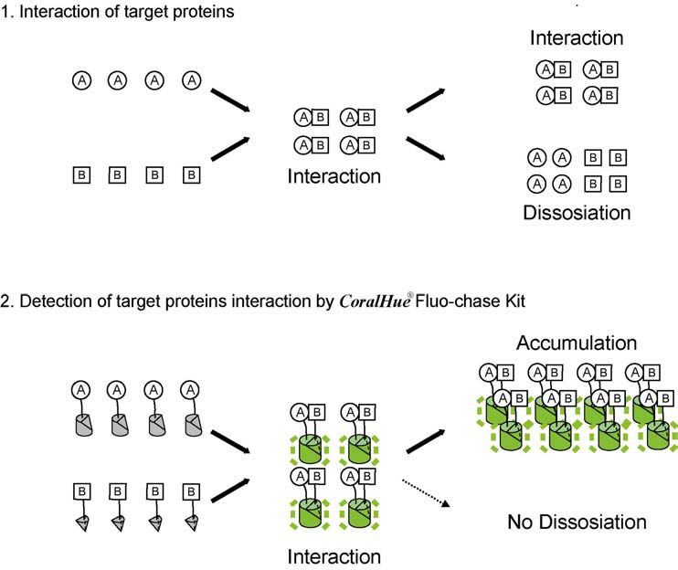
RESEARCH USE ONLY

    Table of Contents

       I. Introduction…………………………………………………………………………..                                    3

      II. Product Components and Storage Conditions……………………..……………                      5

     III. Additional Materials Required………………………….…...…………...……….                       5

     IV. Feature of CoralHue® Fluo-chase Kit……………………….………………..…… 6

      V. Overview of the CoralHue® Fluo-chase Kit procedure……………...………….                8

     VI. Photophysical properties of CoralHue® monomeric Kusabira-Green (mKG).. 9

    VII. Plasmid Maps and Primers of CoralHue® Fluo-chase Kit………………........             10

    VIII. Protocols………………………………………………………………...…..…….....                                15

     IX. Troubleshooting Guide…………………………………………………...……….... 20

      X. References……………………………………………………………………....…..... 21

    XI. Appendix ………………………………………………………………………………. 22

    XII. List of Figures …………………………………………………………………………. 23

15 B Constitution Way · Woburn, MA 01801 · Phone: 1.800.200.5459 · Fax: 781-939-6963 · www.mblintl.com
                                                 2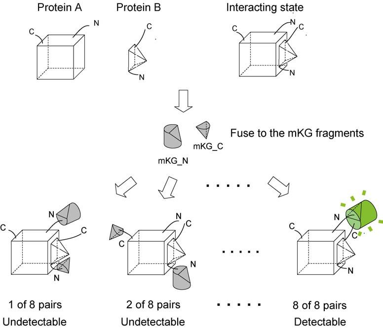
I.      Introduction
           Amalgaam has developed, as the first in the world, the CoralHue® Fluo-chase Kit
     which enables visualization of protein-protein interactions as fluorescent signals in
     mammal cells within 24 hours using the new fluorescent protein CoralHue®
     Kusabira-Green, as a reporter protein.
           Recently, numerous proteomics studies in post-genome research have been
     carried out. In these studies, protein-protein interaction assays are noteworthy from
     various views including investigation of drug discovery targets. Yeast two-hybrid
     (Y2H) assay is widely known as a typical example of protein-protein interaction assay.
     In the Y2H method, two target protein genes are fused to a DNA-binding domain gene
     and a transcriptional activator domain gene, respectively. When both target proteins
     interact, the function of the fused transcriptional activator recovers, resulting in
     expression of β-galactosidase, a reporter molecule. The Y2H method is not suited for
     interactions assay such as membrane proteins, because the protein interactions occur
     in the nuclei, and is also not suited for the case that protein itself has transcription
     activity. As a result, there is a problem that the Y2H method is not sufficient to
     conclude target protein interactions because it has a high false positive rate.
           CoralHue® Fluo-chase Kit can detect protein-protein interactions as fluorescent
     signals using the protein fragment complementation method. The gene of CoralHue®
     monomeric Kusabira-Green (mKG), a reporter protein, is divided into two fragments
     (mKG_N fragment and mKG_C fragment) which are respectively fused to the target
     protein genes to investigate the interactions. When the expressed target proteins don’t
     interact, mKG_N fragment and mKG_C fragment cannot approach each other and
     cannot emit fluorescence. However, when target proteins interact, divided mKG
     fragments spatially approach each other and the local effective concentration increases.
     As a result, mKG fragments form a steric structure before dividing and the
     chromophore emits fluorescence. The fluorescent signals can be detected depending on
     the fused target protein-protein interactions (Figure 1).
           CoralHue® Kusabira-Green fluorescent protein fragment has no false positives
     because it cannot reconstruct the original steric structure and form chromophore
     unless the local effective concentration is increased by two target protein-protein
     interactions. Additionally, as the fluorescent proteins which constitute the
     chromophore cannot be dissociated, reconstructed CoralHue® Kusabira-Green
     fluorescent proteins accumulate, resulting in high-sensitivity analysis even in weak
     protein-protein interactions (Figure 2).
           Various structure of protein complexes are formed by protein interactions. In
     some of the protein complexes for which we would like to study the interactions, there
     is a possibility that fluorescence cannot be detected because two fluorescent protein
     fragments cannot approach the interacted target protein because of steric problems
     and the fluorescent proteins can’t be reconstructed. With the CoralHue® Fluo-chase Kit,
     a plasmid, where each target protein gene is fused to the 5’-end and 3’-end of divided
     CoralHue® Kusabira-Green gene N-terminal fragment and the 5’-end and 3’-end of
     CoralHue® Kusabira-Green gene C-terminal fragment, is made. As a result, the
     detection rate of protein-protein interactions can be improved by making a plasmid
     which expresses the fused proteins with different locations between CoralHue®

15 B Constitution Way · Woburn, MA 01801 · Phone: 1.800.200.5459 · Fax: 781-939-6963 · www.mblintl.com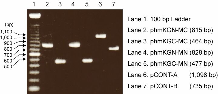
RESEARCH USE ONLY

    Kusabira-Green fluorescent protein fragments and target proteins and inserting them
    into culture cells with different combinations.
          FRET (Fluorescence Resonance Energy Transfer) is well known as one of the
    analysis technique of protein-protein interactions using fluorescent proteins. FRET
    can detect both the state in which target proteins are interacting (ON) and the state in
    which target proteins are not interacting (OFF) in real-time, while CoralHue®
    Fluo-chase Kit can gather the history of the ON state as fluorescent signals. CoralHue®
    Fluo-chase Kit simply measures cumulated fluorescent signals and is suited for
    measuring many samples while FRET needs to measure signals at certain times for
    imaging. Once the condition for detecting fluorescence is set, the change of interactions
    under various conditions including the addition of drugs such as inhibitors and the
    change of temperature can be analyzed with high-throughput.
          CoralHue® Fluo-chase Kit can simply, without an enzyme or substrate, detect
    protein-protein interactions as fluorescent signals by introducing subcloned plasmid
    which targets the protein gene into cultured cells.

    Figure 1. Principle of CoralHue® Fluo-chase Kit

    The state of No Fluorescence. Because there is no interaction between target protein A
    and B that are fused to the mKG fragments (Left).
    The state of No Fluorescence. Divided mKG fragments spatially approach each other
    and local effective concentration increases by interaction of target protein A and B
    (Center).
    The state of Fluorescence. The association between mKG_N fragment and the mKG_C
    fragment allows maturation to form the peptide fluorophore followed by production of
    a fluorescence signals (Right).

15 B Constitution Way · Woburn, MA 01801 · Phone: 41.800.200.5459 · Fax: 781-939-6963 · www.mblintl.com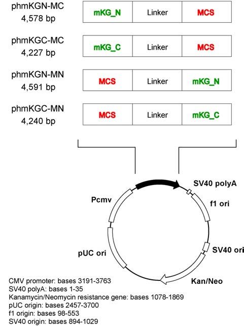
RESEARCH USE ONLY

      II.       Product Components and Storage Conditions
    Product                                                 Size                   Product. #
    CoralHue® Fluo-chase Kit                               1 system                AM-1100
    Components:
                (Plasmids)
            ・   phmKGN-MC                                  Red         (10 µg: Dry form)
            ・   phmKGC-MC                                  Blue        (10 µg: Dry form)
            ・   phmKGN-MN                                  Yellow      (10 µg: Dry form)
            ・   phmKGC-MN                                  Green       (10 µg: Dry form)
            ・   pCONT-A                                    Violet      (10 µg: Dry form)
            ・   pCONT-B                                    White       (10 µg: Dry form)
                (Primers)
            ・   MN-Forward primer                          Natural     (10 nmol: Dry form)
            ・   MC-Reverse primer                          Natural     (10 nmol: Dry form)

    Storage Conditions: Store at -20oC in sterilized distilled water. See the expiration data on
    the product information label.

      III.      Additional Materials Required
      You will need the following reagents and equipment

        ・        Restriction enzymes (BamH I, Kpn I, Pst I, EcoR I, Xho I, Hind III, Not I)
        ・        Subcloning related materials (Thermocycler, DNA polymerase, DNA Ligase)
        ・        Competent cells, LB-Kanamycin agar plates, LB-Kanamycin medium
        ・        Cell culture related materials (Mammalian cells, Cell culture medium, Cell
                culture dish, Plate)
        ・        Transfection reagent
        ・        Buffer for fluorescence detection (HBSS, PBS, Good's Buffer)
        ・        Fluorometric detector (Fluorescent microscopy, Fluorescent spectrometer,
                Fluorescent plate reader)

15 B Constitution Way · Woburn, MA 01801 · Phone: 51.800.200.5459 · Fax: 781-939-6963 · www.mblintl.com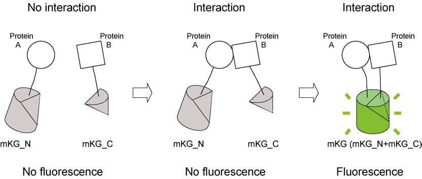
RESEARCH USE ONLY

      IV.     Features of CoralHue® Fluo-chase Kit

    Feature I.
       Once the maturation of peptide fluorophore is constituted by the association of mKG
       fragments, the bimolecular fluorescent mKG complex cannot reversibly be
       dissociated. Therefore reconstituted mKG fluorescent protein accumulates. This
       accumulation leads to the amplification of the fluorescent signal, which allows a
       high-sensitivity analysis even in weak protein-protein interactions (Figure 2).

    Figure 2. Accumulation of protein-protein interaction as a fluorescent signal

    The formation of protein complex reflects equilibrium binding affinities of the
    interaction partners (1). As bimolecular fluorescent complex formation is not reversible
    under the various conditions, the fluorescent signal derived from CoralHue®
    Kusabira-Green protein accumulates, which allows a high-sensitivity analysis (2).

15 B Constitution Way · Woburn, MA 01801 · Phone: 61.800.200.5459 · Fax: 781-939-6963 · www.mblintl.com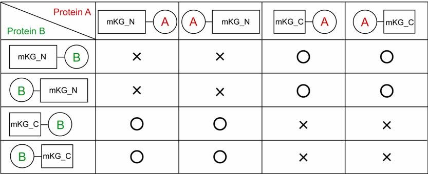
RESEARCH USE ONLY

    Feature II.
       To date, the wide structural diversity of intermolecular proximity of both
       polypeptides ends has made Bimolecular Fluorescent Complementation Assays
       difficult. In the case the fluorescent fragment-fused ends are located structurally
       distant, the optimal fluorescent signal has not been detected.
       CoralHue® Fluo-chase Kit provides 4 cloning plasmids which making a plasmid
       which expresses the fused proteins with different locations between CoralHue®
       Kusabira-Green fluorescent protein fragments and target proteins and inserting
       them into culture cells with different combinations (Figure 3).

    Figure 3. The mechanism of high probability detection of fluorescent signal
    In the protein complex which is composed of protein A and B, the N terminal of protein
    A is located on the same side of the C terminal of protein B. Whereas the C terminal of
    protein A is on the opposite side of the N terminal of protein B. In this case, an optimal
    signal is produced by fusing mKG_N to the N terminal of protein A and fusing mKG_C
    to the C terminal of protein B.

15 B Constitution Way · Woburn, MA 01801 · Phone: 71.800.200.5459 · Fax: 781-939-6963 · www.mblintl.com
RESEARCH USE ONLY
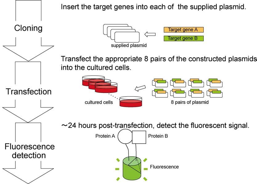
V. Overview of the CoralHue® Fluo-chase Kit procedure
CoralHue® Fluo-chase Kit procedure comprises the following 3 steps (Figure 3.).
1: Cloning target gene of interest into CoralHue® Fluo-chase Kit vectors
2: Transfection to the culture cells
3: Fluorescence detection by protein-protein interaction
Figure 4. Overview of the CoralHue® Fluo-chase Kit procedure
15 B Constitution Way · Woburn, MA 01801 · Phone: 81.800.200.5459 · Fax: 781-939-6963 · www.mblintl.comRESEARCH USE ONLY
VI. Photophysical Properties of CoralHue® monomeric
Kusabira-Green (mKG)
CoralHue® monomeric Kusabira-Green (mKG) is the mutant of orange-emitting fluorescent
protein, Kusabira-Orange from the stony coral Fungia concinna.
In contrast to the original protein, mKG reveals bright green fluorescence with excitation
maximum at 494 nm and emission maximum at 506 nm (Table 1). mKG sequence is
codon-optimized for higher expression in mammalian cells.
Figure 5. Excitation, emission and absorption spectra
Excitation (dot line) and emission spectra (solid line)(Panel A). Absorption spectrum
(Panel B). Curves are normalized.
Table 1. Photophysical properties of CoralHue® monomeric Kusabira-Green
15 B Constitution Way · Woburn, MA 01801 · Phone: 91.800.200.5459 · Fax: 781-939-6963 · www.mblintl.comRESEARCH USE ONLY
VII. Plasmid
CoralHue® Fluo-chase Kit cloning vectors contains the following elements.
・ cytomegalovirus (CMV) promoter for high level expression in a wide range of
mammalian cells
・ Kanamycin resistance gene for selection in E. coli.
・ Neomycin resistance gene for selection of stable line cells
・ multiple cloning site (MCS) restriction enzyme site (BamHI, KpnI, PstI, EcoRI, XhoI,
HindIII and NotI )
・ Flexible linker for relieves steric hindrance between the target protein and mKG (24
amino acids)
CoralHue® Fluo-chase Kit provides 4 cloning plasmids which have the same basal
backbone (Figure 6.). In each of 4 cloning plasmid, mKG fragments and MCS have
changed places beyond the flexible linker (Figure 6.). Each of the cloning plasmids has
the same restriction sites in the same frame (Figure 7, Figure 8.).
Figure 6. Map and Features of CoralHue® Fluo-chase Kit vectors
15 B Constitution Way · Woburn, MA 01801 · Phone:10
1.800.200.5459 · Fax: 781-939-6963 · www.mblintl.comRESEARCH USE ONLY
CoralHue® Fluo-chase Kit vectors
A. Cloning vectors
・ phmKGN-MC
From the 5’-end, mKG N fragment (mKG_N), linker and MCS are located on
phmKGN-MC (Figure 7.). (Clone target gene into downstream of mKG_N)
・ phmKGC-MC
From the 5’-end, mKG C fragment (mKG_C), linker and MCS are located on
phmKGC-MC (Figure 7.). (Clone target gene into downstream of mKG_C)
・ phmKGN-MN
From the 5’-end, MCS, linker and mKG N fragment (mKG_N) are located on
phmKGN-MCN (Figure 8.). (Clone target gene into the upstream of mKG_N)
・ phmKGC-MN
From the 5’-end, MCS, linker and mKG C fragment (mKG_C) are located on
phmKGC-MC (Figure 8.). (Clone target gene into the upstream of mKG_C)
B. Positive control
・ pCONT-A
From the 5’-end, p50 partial domain from NF-κB complex, linker and mKG N
fragment (mKG_N) are located on pCONT-A (Figure 9.).
・ pCONT-B
From the 5’-end, p65 partial domain from NF-κB complex, linker and mKG C
fragment (mKG_C) are located on pCONT-B (Figure 9.).
Sequencing Primers
・MN-Forward primer
MN-Forward primer help to sequence from the 5’-end of target gene cloned into
phmKGN-MN and phmKGC-MN (Figure 8.).
・MC-Reverse primer
MC-Reverse primer help to sequence from the 3’-end of target gene cloned into
phmKGN-MC and phmKGC-MC (Figure 7.).
*About concentration of primer*
Add 100 µl sterile water to make 10 µM primer solution.
15 B Constitution Way · Woburn, MA 01801 · Phone:11
1.800.200.5459 · Fax: 781-939-6963 · www.mblintl.comRESEARCH USE ONLY
Figure 7. Plasmid Map and Features of MC type of CoralHue® Fluo-chase Kit cloning
vector
15 B Constitution Way · Woburn, MA 01801 · Phone:12
1.800.200.5459 · Fax: 781-939-6963 · www.mblintl.comRESEARCH USE ONLY
Figure 8. Plasmid Map and Features of MN type of CoralHue® Fluo-chase Kit cloning
vector
15 B Constitution Way · Woburn, MA 01801 · Phone:13
1.800.200.5459 · Fax: 781-939-6963 · www.mblintl.comRESEARCH USE ONLY
Figure 9. Plasmid MAP of CoralHue® Fluo-chase Kit Positive Control vector
For the full sequences of either CoralHue® Fluo-chase Kit vector, refer to MBL web site.
https://res.mbl.co.jp/catalog/flprotein.html
15 B Constitution Way · Woburn, MA 01801 · Phone:14
1.800.200.5459 · Fax: 781-939-6963 · www.mblintl.comRESEARCH USE ONLY
VIII. Protocols
PLEASE READ THROUGH ENTIRE PROTOCOL BEFORE BEGINNING
A. Cloning target genes into the CoralHue® Fluo-chase Kit Cloning Vectors
1. Amplify target genes
1-1. Amplify target PCR product using standard protocol. It is important to the
properly design target PCR primers that must be append an appropriate
restriction enzyme.
Note: To design appropriate primers in case of partial domain of target gene
The initial translation codon ATG (Methionin) must be added to the 5’-end of
target gene.
For MC type plasmids, stop codons are included in the MCS in all three
reading frames. Depending on which restriction enzymes are used for cloning,
additional amino acids may be present at the C-terminus of target protein.
1-2. Go to the following step that genomic DNA, plasmid DNA, or cDNA may be
used as target gene of interest.
2. Restriction Enzyme Digestion
2-1. Digest PCR products/plasmids of target gene and CoralHue® Fluo-chase Kit
cloning vectors with restriction enzymes.
2-2. Separate the digested target gene and CoralHue® Fluo-chase Kit cloning
vectors with gel electrophoresis.
3. Construction recombinant fusion protein
3-1. Prepare the ligation reaction mixture by combining the following components
(Table 2.).
3-2. Transforming each plasmid mixture to the competent cells.
3-3. Plate the competent cells to LB-Kanamycin plates and incubate at 37oC. Pick
up the single colony and incubate with LB-Kanamycin medium.
3-4. Isolate the plasmid from selected colonies using standard protocols.
15 B Constitution Way · Woburn, MA 01801 · Phone:15
1.800.200.5459 · Fax: 781-939-6963 · www.mblintl.comRESEARCH USE ONLY
Table 2. Paradigm of Target Protein A and B Construction
Note: All of the plasmid mentioned above does not have to be constructed, when the
proper positions or unsuitable positions to fuse target protein are predicted judging
from the tertiary structure or the presence of signal sequence in target protein.
4. Analyze plasmid DNA for the presence and orientation of target gene by PCR or
restriction enzyme digestion.
Note: You may use CoralHue® Fluo-chase Kit primers for any PCR or sequencing
(See Appendix A, Figure 10.)
B. Transfection
1. Prepare the mixture for transformation
1-1. Mix two of the eight plasmids including target gene in a manner that mKG_N
fragment and mKG_C fragment are paired (Table 3).
1-2. Mix pCONT-A and pCONT-B as a positive control mixture (Table 4.).
Note: 24 hours after post-transfection, fluorescence signals can be detected using
fluorescent microscopy (See Appendix B and Figure 11.).
1-3. Prepare the negative control mixture as Table 4. Mix two of the four
plasmids which do not include target gene in a manner that mKG_N fragment
and mKG_C fragment are paired.
Note: 24 hours after post-transfection, any fluorescence signals cannot be detected
(See Appendix C and Figure 12.)
Note: The proper quantity of plasmid for transfection.
Although it depends on the transfection reagent you use, 1~2 µg of total
amount of DNA will be optimal for 35-mm dish.
2. Transfection into cultured cell
Transfect each of the plasmid mixtures into the cultured cell. Use
commercially supplied transfection reagent.
15 B Constitution Way · Woburn, MA 01801 · Phone:16
1.800.200.5459 · Fax: 781-939-6963 · www.mblintl.comRESEARCH USE ONLY
Table 3. Preparation of Appropriate Pairs of Plasmid Mixtures Containing Target
Genes
○ : Appropriate pairs between mKG_N fragment and mKG_C fragment fusion
proteins.
× : Inappropriate pairs between mKG_N fragment and mKG_C fragment fusion
proteins.
Table 4. Preparation of Appropriate Pairs of Plasmid Mixtures for Positive and
Negative Control
C. Fluorescence detection
24 hours after post-tranfection, detect or measure fluorescence with fluorometric
detector. Cell cultured medium is recommended to displacement to transparent
medium for fluorescent detection.
15 B Constitution Way · Woburn, MA 01801 · Phone:17
1.800.200.5459 · Fax: 781-939-6963 · www.mblintl.comRESEARCH USE ONLY
Note: The fluorescence images of positive control and negative control (See
Appendix B and C, Figure 11. and 12.)
Detection of Fluorescent Signal
1. Fluorescent Microscopy
Use appropriate filters set for observing green fluorescence signal such as FITC.
Replace cell culture medium by an achromatic pellucid buffer (HBSS, PBS,
Good’s Buffer, etc).
Investigate the optimal imaging condition by using cells expressing positive
control mixture
.
* Cell culture dishes for Fluorescent Microscopy *
Using glass bottom cell culture dishes is recommended for high-resolution
fluorescence imaging. Some plastic bottom cell culture dishes can be used with
low magnification objective lenses such as X10 or X20.
* To avoid photobleaching *
Detect fluorescence images at weak excitation condition. Irradiation of strong
excitation for a long time causes undesirable photobleaching.
2. Fluorescence Spectrometer
Fluorescent intensity and excitation/fluorescence spectra can be measured by
suspending cotransfected cells in achromatic pellucid buffer (HBSS, PBS, Good’s
Buffer, etc). Investigate the optimal measuring condition by using cells
expressing positive control mixture.
Fluorescent signal may not be acquired in the case of the low transfection
efficiency, scattering excitation light, or high autofluorescence.
* Measuring procedure *
The excitation and emission peak of mKG is 494nm and 506nm (Figure 5, Table
1.). Using quartz cells for measuring your sample is recommended.
For acquiring fluorescence spectrum, excite your sample at around 440nm to
495nm, and acquire the fluorescence spectrum from 500nm to 600nm.
For acquiring fluorescence intensity, investigate the optimal excitation
wavelength between 470nm to 495nm and the optimal slit width to avoid
15 B Constitution Way · Woburn, MA 01801 · Phone:18
1.800.200.5459 · Fax: 781-939-6963 · www.mblintl.comRESEARCH USE ONLY
leakage of excitation light. Detect the fluorescent intensity at around 506nm.
3. Fluorescent Plate Reader
Cell-based fluorescent assays can be performed with CoralHue® Fluo-chase Kit.
Use filters set appropriate for detecting green fluorescence signal such as FITC.
To avoid autofluorescence by cell culture med, replace them by an achromatic
pellucid buffer (HBSS, PBS, Good’s Buffer, etc). Investigate the optimal detecting
condition by using cells expressing positive control mixture.
Fluorescent signal may not be obtained in the case that the instrument is not
suited or the transfection efficiency is low.
*Recommended micro plate*
For a cell-based fluorescent assay, black cell culture plates are recommended.
15 B Constitution Way · Woburn, MA 01801 · Phone:19
1.800.200.5459 · Fax: 781-939-6963 · www.mblintl.comRESEARCH USE ONLY
IX. Troubleshooting Guide
A. Weak signals or undetectable signals
1. The case that cannot be detected by positive control mixture.
There can be problems where the measurement conditions for the fluorescent
detecting instrument are not suited or the transfection efficiency is low.
Please check the conditions in which the fluorescence can be detected using
cells expressing positive control mixture.
2. The case of weak signals that can be detected by protein-protein interactions
assay
2-1 It is considered that target protein-protein binding is weak or the effective
rate of reconstruction of mKG is low because of the location of mKG
fragments. Please observe it after a while (more than 24 hours). As the
mKG which formed chromophore is accumulated, fluorescent intensity can
be increased by elongating the incubation time after post-transfection.
2-2 In the case that target gene is long (more than 2Kb), there is a possibility
for the size of the target protein to prevent approaching and reconstitution
of mKG fragments. If you know the domain of target protein interactions,
fluorescent signals can be detected using only the gene arrangement of the
domain in some cases.
B. High background
Many autofluorescent materials such as serum are included in cell culture
medium. It is recommended to observe and measure fluorescent signals after
replacing them by an achromatic pellucid buffer (HBSS, PBS, Good’s Buffer,
etc).
15 B Constitution Way · Woburn, MA 01801 · Phone:20
1.800.200.5459 · Fax: 781-939-6963 · www.mblintl.comRESEARCH USE ONLY
X. References
Tom K. Kerppola
Complementary methods for studies of protein interactions in living cells.
Nat Methods. 2006 Dec;3(12):969-71.
Tom K. Kerppola
Visualization of molecular interactions by fluorescence complementation.
Nat Rev Mol Cell Biol. 2006 Jun;7(6):449-56.
Karasawa, S et al.
Cyan-emitting and orange-emitting fluorescent proteins as a donor/acceptor pair for
fluorescence resonance energy transfer.
Biochem. J. 2004 Jul 1;381(Pt 1):307-12.
NOTE
CoralHue® Fluo-chase Kit Does Not Guarantee Fluorescence
Detection of all Protein-Protein Interactions.
CoralHue® Fluo-chase kit used in this product was co-developed with the Laboratory for
Cell Function and Dynamics, the Advanced Technology Development Center, the Brain
Science Institute, and the Institute of Physical and Chemical Research (RIKEN) (lab
head Dr. Atsushi Miyawaki).
The use of CoralHue® monomeric Kusabira-Green requires a license. Amalgaam grants
non-profit research organizations an international, royalty-free, non-exclusive, limited
license to use this product for non-commercial research use only. This license excludes
the right to sell or transfer this product, its components, or modifications of this
product to third parties. Any other uses require a license. The use of this product by
for profit organizations, for either commercial or non-commercial use, requires a
license.
PATENT PENDING
15 B Constitution Way · Woburn, MA 01801 · Phone:21
1.800.200.5459 · Fax: 781-939-6963 · www.mblintl.comRESEARCH USE ONLY
Appendix
A: Electrophoretic profile of PCR products with CoralHue® Fluo-chase Kit primers
The following basic protocol serves as a general guideline for any PCR purification.
Optimal reaction conditions (incubation times and temperatures, concentration of Taq
DNA polymerase, primers, MgCl2, and template DNA) vary and need to be optimized.
Additional Materials Required
・ Thermocycler
・ Taq DNA polymerase 2.5 U/µL
・ Taq DNA polymerase buffer
・ 2.5 mM dNTPs
・ Template DNA
・ Sterilized distilled water
General reaction mixture for PCR (total 50 µl)
Components Volume (µl)
10 µM MN-forward primer 1
10 µM MC-Reverse primer 1
Taq DNA polymerase buffer 5
Taq DNA polymerase 0.5
2.5 mM dNTPs 3
Template DNA 1
Sterilized distilled water 38.5
50
total
PCR conditions
Example: Amplification of DNA fragment about 450~1100 bp
94oC 5 min
94oC 30 sec
50oC 30 sec 25 cycle
72oC 1 min
72oC 7 min
4oC ∞
15 B Constitution Way · Woburn, MA 01801 · Phone:22
1.800.200.5459 · Fax: 781-939-6963 · www.mblintl.comRESEARCH USE ONLY
Figure 10. Electrophoretic profile of PCR products with CoralHue® Fluo-chase Kit
primers.
lane 1: DNA marker (100 bp ladder), lane 2~7: Electrophoretic profile of PCR products.
Each CoralHue® Fluo-chase Kit cloning vector was amplified with MN-Forward primer
and MC-Reverse primer. () shows length of PCR products.
B: Fluorescence Image of Positive Control
HEK 293T cells were inoculated to the 35-mm glass bottom dish. The mixture with
each pCONT-A and pCONT-B 0.5 µg were transfected to HEK 293T cells with
commercially supplied transfection reagent. 24 hours after post-transfection,
fluorescent could be detected with fluorescent microscopy.
pCONT-A / pCONT-B
Figure 11. Fluorescence image of HEK 293T cells expressing positive control
Fluorescent microscopy images of HEK 293T cells expressing positive control (Left
panel), Phase contrast (Right panel).
15 B Constitution Way · Woburn, MA 01801 · Phone: 1.800.200.5459 · Fax: 781-939-6963 · www.mblintl.com
23RESEARCH USE ONLY
C: Fluorescence Images of Negative Control
HEK 293T cells were inoculated to the 35-mm glass bottom dish. The mixture with
negative controls was transfected to HEK 293T cells with commercially supplied
transfection reagent. 24 hours after post-transfection, fluorescent could not be detected
with fluorescent microscopy.
NC-1
NC-2
NC-3
NC-4
Figure 12. Fluorescence images of HEK 293T cells expressing negative controls
Fluorescent microscopy images of HEK 293T cells expressing negative controls (Left
panel), Phase contrast (Right panel). See the below or Table 4 for the combination of
negative controls
NC-1: phmKGN-MC/phmKGC-MC, NC-2: phmKGN-MC/phmKGC-MN,
NC-3: phmKGN-MN/phmKGC-MC, NC-4: phmKGN-MN/phmKGC-MN
15 B Constitution Way · Woburn, MA 01801 · Phone: 1.800.200.5459 · Fax: 781-939-6963 · www.mblintl.com
24RESEARCH USE ONLY
D: Properties of CoralHue® monomeric Kusabira-Green
Figure 13. The DNA sequence and amino acid sequence of CoralHue® monomeric
Kusabira-Green fragment
Table 5. Base Counts and Molecular Weight of CoralHue® monomeric
Kusabira-Green.
15 B Constitution Way · Woburn, MA 01801 · Phone: 1.800.200.5459 · Fax: 781-939-6963 · www.mblintl.com
25RESEARCH USE ONLY
XII. List of Figures
Figure 1. Principle of CoralHue® Fluo-chase Kit……………………………….…………….6
Figure 2. Accumulation of the history of protein interaction as a fluorescent signal……8
Figure 3. The mechanism of high probability detection of fluorescent signal………….. 9
Figure 4. Overview of the CoralHue® Fluo-chase Kit procedure…………………………. 10
Figure 5. Excitation, emission and absorption spectra of CoralHue® monomeric
Kusabira-Green……………………………………….…………………………….. 11
Figure 6. Map and Features of CoralHue® Fluo-chase Kit vectors……………………….. 12
Figure 7. Plasmid Map and Features of MC type of CoralHue® Fluo-chase Kit cloning vector
……………………………………………………………………………………………………14
Figure 8. Plasmid Map and Features of MN type of CoralHue® Fluo-chase Kit cloning vector
………………………………………………………………………………………………………. 15
Figure 9. Plasmid MAP of CoralHue® Fluo-chase Kit Positive Control vector…………16
Figure 10. Electrophoretic profile of PCR products with CoralHue® Fluo-chase Kit
primers……………………………………………………………………………26
Figure 11. Fluorescence image of HEK 293T cells expressing positive control……… 26
Figure 12. Fluorescence images of HEK 293T cells expressing negative controls……27
Figure 13. The DNA sequence and amino acid sequence of CoralHue® monomeric
Kusabira-Green fragment……………………………………………………………………… 28
List of Tables
Table 1.Photopysical properties of CoralHue® monomeric Kusabira-Green………………11
Table 2. Paradigm of Target Protein A and B Construction………………………….. 18
Table 3. Preparation of Appropriate Pairs of Plasmid Mixtures containing target
genes……………………………..…………………………………………………. 20
Table 4. Preparation of Appropriate Pairs of Plasmid Mixtures for Positive and
Negative Control…………………………………………………………………… 20
Table 5. Base Counts and Molecular Weight of CoralHue® monomeric Kusabira-Green.
…………………………………………………………………………………………………… 28
15 B Constitution Way · Woburn, MA 01801 · Phone: 1.800.200.5459 · Fax: 781-939-6963 · www.mblintl.com
26You can also read