Dell EMC PowerEdge XR11 and XR12 - Technical Guide
←
→
Page content transcription
If your browser does not render page correctly, please read the page content below
Dell EMC PowerEdge XR11 and XR12
Technical Guide

Part Number: E73S Series
Regulatory Type: E73S001
July 2021
Rev. A00
Notes, cautions, and warnings

     NOTE: A NOTE indicates important information that helps you make better use of your product.

     CAUTION: A CAUTION indicates either potential damage to hardware or loss of data and tells you how to avoid
     the problem.

     WARNING: A WARNING indicates a potential for property damage, personal injury, or death.

© 2021 Dell Inc. or its subsidiaries. All rights reserved. Dell, EMC, and other trademarks are trademarks of Dell Inc. or its subsidiaries. Other
trademarks may be trademarks of their respective owners.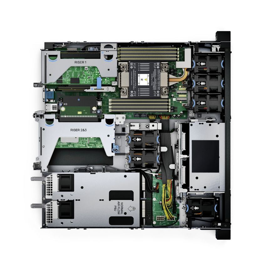
Contents

Chapter 1: System overview.......................................................................................................... 6
  Key workloads...................................................................................................................................................................... 6
  New technologies................................................................................................................................................................ 6

Chapter 2: System features.......................................................................................................... 8

Chapter 3: Chassis views and features.........................................................................................10
  Chassis views......................................................................................................................................................................10
     Front view of XR11 front accessed chassis........................................................................................................... 10
     Front view of XR11 rear accessed chassis.............................................................................................................. 11
     Front view of XR12 front accessed chassis...........................................................................................................12
     Front view of XR12 rear accessed chassis.............................................................................................................13
     Rear view of XR11 front accessed chassis............................................................................................................. 14
     Rear view of XR11 rear accessed chassis...............................................................................................................14
     Rear view of XR12 front accessed chassis ........................................................................................................... 15
     Rear view of XR12 rear accessed chassis.............................................................................................................. 15
     Inside the XR11 front accessed chassis.................................................................................................................. 16
     Inside the XR11 rear accessed chassis.................................................................................................................... 18
     Inside the XR12 front accessed chassis.................................................................................................................20
     Inside the XR12 rear accessed chassis...................................................................................................................22
     Quick Resource Locator (QRL)................................................................................................................................23

Chapter 4: Processor.................................................................................................................. 25
  Processor features .......................................................................................................................................................... 25
  Supported processors for XR11 and XR12...................................................................................................................25

Chapter 5: Memory subsystem.................................................................................................... 27
  Supported memory............................................................................................................................................................27

Chapter 6: Storage......................................................................................................................28
  Supported drives............................................................................................................................................................... 28
  Internal storage configuration matrix for XR11...........................................................................................................28
  Internal storage configuration matrix for XR12..........................................................................................................29
  External storage................................................................................................................................................................ 30

Chapter 7: Expansion cards and expansion card risers..................................................................31
  Expansion cards and risers for the PowerEdge XR11 system................................................................................. 31
     Expansion card installation guidelines..................................................................................................................... 31
  Expansion cards and risers for the PowerEdge XR12 system................................................................................ 34
     Expansion card installation guidelines.....................................................................................................................34

Chapter 8: Power, thermal, and acoustics................................................................................... 39
  Power for XR11 and XR12................................................................................................................................................39
  Thermal for XR11 and XR12.............................................................................................................................................40

                                                                                                                                                          Contents                   3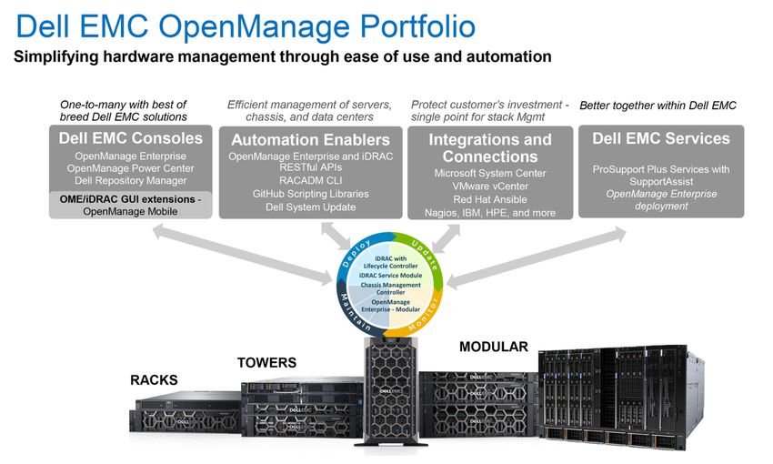
Acoustics............................................................................................................................................................................. 40
           Acoustical design for XR11 and XR12......................................................................................................................40

    Chapter 9: Rack, rails, and cable management.............................................................................42
      Rails information................................................................................................................................................................ 42
         Sliding rails in 2-post rack......................................................................................................................................... 43
         Sliding rails in 4-post rack......................................................................................................................................... 44
         Sliding rails in Pelican transit case...........................................................................................................................46
      Cable Management Arm.................................................................................................................................................. 46
      Strain Relief Bar................................................................................................................................................................. 47

    Chapter 10: Supported Operating Systems.................................................................................. 48

    Chapter 11: Dell EMC OpenManage systems management............................................................49
      Server and Chassis Managers........................................................................................................................................50
      Dell EMC consoles............................................................................................................................................................ 50
      Automation Enablers........................................................................................................................................................ 50
      Integration with third-party consoles...........................................................................................................................50
      Connections for third-party consoles.......................................................................................................................... 50
      Dell EMC Update Utilities................................................................................................................................................50
      Dell resources.....................................................................................................................................................................50

    Chapter 12: Dell Technologies Services .......................................................................................52
      Dell EMC ProDeploy Enterprise Suite ......................................................................................................................... 52
         Dell EMC ProDeploy Plus...........................................................................................................................................53
         Dell EMC ProDeploy....................................................................................................................................................53
         Basic Deployment........................................................................................................................................................ 53
         Dell EMC Server Configuration Services...............................................................................................................53
         Dell EMC Residency Services...................................................................................................................................53
      Dell EMC Remote Consulting Services........................................................................................................................ 53
      Dell EMC Data Migration Service..................................................................................................................................53
      Dell EMC ProSupport Enterprise Suite........................................................................................................................ 53
      Dell EMC ProSupport Plus for Enterprise................................................................................................................... 54
      Dell EMC ProSupport for Enterprise............................................................................................................................ 54
      Dell EMC ProSupport One for Data Center................................................................................................................55
      ProSupport for HPC.........................................................................................................................................................55
      Support Technologies...................................................................................................................................................... 56
      Dell Technologies Education Services.......................................................................................................................... 57
      Dell Technologies Consulting Services.........................................................................................................................57
      Dell EMC Managed Services...........................................................................................................................................57

    Chapter 13: Appendix A. Additional specifications....................................................................... 58
      Chassis dimensions........................................................................................................................................................... 58
      Chassis weight................................................................................................................................................................... 60
      Video specifications..........................................................................................................................................................60
      USB ports............................................................................................................................................................................60
         USB ports specifications for XR11...........................................................................................................................60
         USB ports specifications for XR12...........................................................................................................................61
      Power Supply Units for XR11 and XR12........................................................................................................................ 61

4   Contents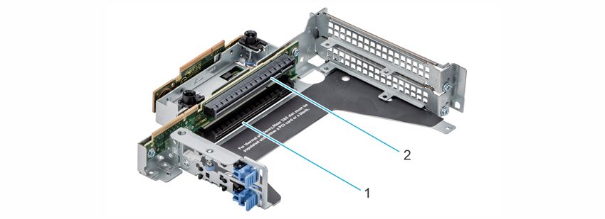
Power supply efficiency for XR11 and XR12..........................................................................................................63
   Environmental Specifications for XR11 and XR12...................................................................................................... 63
     ASHRAE A3/A4 Rugged support restriction for XR11 and XR12..................................................................... 65
     Thermal restrictions.................................................................................................................................................... 67

Chapter 14: Appendix B. Standards compliance........................................................................... 69

Chapter 15: Appendix C Additional resources...............................................................................70

                                                                                                                                                    Contents                  5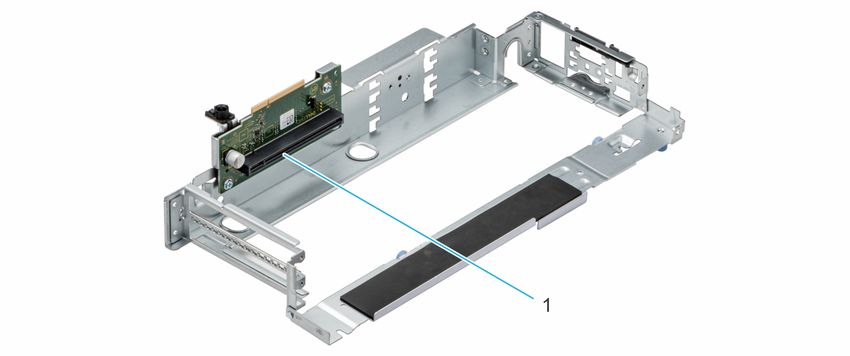
1
                                                                                  System overview
The Dell™ PowerEdge™ XR11 and XR12 are Dell's latest rugged servers, designed to run complex workloads using highly scalable
memory, I/O, and network options in locations constrained by space or environmental challenges.
The PowerEdge XR11 is a 1-socket, short-depth 1U rugged server.
The PowerEdge XR12 is a 1-socket, short-depth 2U rugged server.
The systems feature the 3 rd Generation Intel Xeon Scalable Processor with up to 8 DIMMs, PCI Express® (PCIe) 4.0 enabled
expansion slots, and a choice of network interface technologies to cover NIC. The PowerEdge XR11 and XR12 systems are
unique platforms designed to optimize computing at the edge with performance in mind. The systems are well suited to operate
at high temperatures in harsh or space-constrained environments, and are capable of handling demanding processing workloads
and applications such as for the Telecom, Military and Defense industries, as well as, for the commercial sector.
Topics:
•          Key workloads
•          New technologies

Key workloads
There are a diverse set of applications that operate at the Edge and each of these applications has a different set of
requirements.
● Retail Applications - Built with a minimum footprint and enterprise compute to optimize expensive retail space and deliver
  a targeted virtual experience, including video surveillance analytics, point of sale analytics and IoT device aggregation and
  analytics
● Telco / 5G - Compact and rugged design capable of supporting accelerators for remote private networks requiring
  AI/ML/DL type workloads. Use cases include MEC, CDN and VRAN
● Military - Reliable DC power in a hardened chassis to support mobile data centers deployed globally to collect and analyze
  reconnaissance data

New technologies
Table 1. New technologies featured on XR11 and XR12
    Technology                       Detailed description
    3 rd
       Generation Intel® Xeon        ● 10nm process technology
    Scalable Processor               ● Maximum of 36 cores
                                     ● Maximum of 3.5 GHz
                                     ● Maximum of 64 lanes of PCI Express 4.0 links capable of 16 GT/s
                                     ● Maximum TDP: 225 W
                                     Consult the Processor section for specific SKU details.
                                        NOTE: TDP support will vary based on the maximum operating temperature.

    3200 MT/s DDR4 Memory            ● Up to 8 DDR4 channels with 1 DPC; 8 DIMMs in total
                                     ● Speed up to 3200 MT/s (configuration-dependent)
                                     ● Supports DDR4 ECC RDIMM (max: 64 GB) and DDR4 ECC LRDIMM (max: 128 GB)
    Persistent Memory                128 GB Intel Optane DC Persistent Memory 200 Series support on two configurations:
                                     Number of DDR4 DIMMs plus number of Intel Optane Persistent Memory 200 Series
                                     DIMMs

6             System overview
Table 1. New technologies featured on XR11 and XR12 (continued)
Technology                       Detailed description
                                 ● 4+4
                                 ● 6+1
Chassis Orientation              The XR11 and XR12 have two chassis options:
                                 1. Rear accessed chassis also called Normal Airflow (NAF) chassis, where power supplies
                                    and network cards are in the rear
                                 2. Front accessed chassis also called Reverse Airflow (RAF) chassis, where power
                                    supplies and network cards are in the front
                                 The location of the control panel changes with the chassis orientation.
iDRAC9 w/ Lifecycle Controller   The embedded systems management solution for Dell servers features hardware and
                                 firmware inventory and alerting, in-depth memory alerting, faster performance, a
                                 dedicated gigabit port and many more features.
Power Supplies                   ●   60 mm dimension (new PSU form factor for new generation of servers)
                                 ●   Platinum 800 W (WRAC and MM 240 V)
                                 ●   *1100 W -48 V DC
                                 ●   *Platinum 1400 W (WRAC and MM 240 V)
                                     NOTE: *These PSUs are available in Reverse Airflow design for use in Front Accessed
                                     chassis configuration and in Normal Airflow for use in Rear Accessed configuration.

                                                                                               System overview             7
2
                                                                               System features
Table 2. System features of XR11 and XR12
Feature             XR11                                                  XR12
Processor           1x 3 rd Generation Intel® Xeon Scalable Processor     1x 3 rd Generation Intel® Xeon Scalable Processor
Chipset             Intel Lewisburg PCH (Intel® C620 Series Chipset)      Intel Lewisburg PCH (Intel® C620 Series Chipset)

                    8x RDIMM, LRDIMM DDR4 with ECC                        8x RDIMM, LRDIMM DDR4 with ECC
                    Two Intel Optane Persistent Memory 200 series      Two Intel Optane Persistent Memory 200 series
                    configurations: Number of DDR4 DIMMs plus number configurations: Number of DDR4 DIMMs plus
Memory              of Intel Optane Persistent Memory 200 series DIMMs number of Intel Optane Persistent Memory 200
                                                                       series DIMMs
                    ● 4+4
                    ● 6+1                                              ● 4+4
                                                                       ● 6+1

                    4x 2.5 - inch - 12 GB SAS, 6 GB SATA                  6x 2.5-inch - 12 GB SAS, 6 GB SATA
Disk Drives
                    Up to 4x NVMe                                         Up to 6x NVMe

                    ●   PERC 10.5: H345 (Adapter)                         ●   PERC 10.5: H345 (Adapter)
                    ●   PERC 11: HBA355i (Adapter), H755 (Adapter)        ●   PERC 11: HBA355i (Adapter), H755 (Adapter)
Storage
                    ●   External Adapters: H840; HBA355e                  ●   External Adapters: H840; HBA355e
Controllers
                    ●   Software RAID: S150                               ●   Software RAID: S150
                    ●   BOSS-S1 (RAID)                                    ●   BOSS-S1 (RAID)
External Storage    ME484, MD1420 and MD1400                              ME484, MD1420 and MD1400
Supported
                    Up to 2x M.2 Boot Optimized Storage Subsystem         Up to 2x M.2 Boot Optimized Storage Subsystem
M.2 SSD
                    (BOSS-S1)                                             (BOSS-S1)
                    Two riser configuration options:                 Five riser configuration options:
                    ● 3x PCIe Gen4 (one x8 PCIe Gen4 + two x16 PCIe ● 3x PCIe Gen4 (one x8 PCIe Gen4 + two x16
                      Gen4)                                             PCIe Gen4)
                    ● 3x PCIe Gen4 (one x16 PCIe Gen4 + two x16 PCIe ● 3x PCIe Gen4 (one x16 PCIe Gen4 + two x16
                      Gen4)                                             PCIe Gen4)
PCIe Slots
                                                                     ● 4x PCIe Gen 4 (three x8 PCIe Gen4 + one x16
                                                                        PCIe Gen 4)
                                                                     ● 4x PCIe Gen 4 (two x8 PCIe Gen 4 + two x16
                                                                        PCIe Gen 4)
                                                                     ● 5x PCIe Gen4 (five x8 PCIe Gen4)
Integrated LOM      4x 25 GbE SFP+ (Broadcom Thor)                        4x 25 GbE SFP+ (Broadcom Thor)
                    XR11 has two chassis options:                         XR12 has two chassis options:
                    1. Rear Accessed chassis also called Normal Airflow   1. Rear Accessed chassis also called Normal
                       (NAF) chassis where power supplies and network        Airflow (NAF) chassis where power supplies
                       cards are in the rear.                                and network cards are in the rear.
Chassis                    NOTE: Network, Serial, VGA, Power supplies             NOTE: Network, Serial, VGA ports, Power
Orientation
                           and PCIe Slots are accessible in the rear              supplies, Hard drives and PCIe Slots are
                           of the platform and the Hard Drives, Power             accessible in the rear of the platform.
                           button, Status LED, USB and Management
                           port are in the front of the system.

8         System features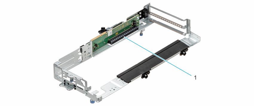
Table 2. System features of XR11 and XR12 (continued)
Feature          XR11                                                    XR12
                 2. Front Accessed chassis also called Reverse           2. Front Accessed chassis also called Reverse
                    Airflow (RAF) chassis where power supplies and          Airflow (RAF) chassis where power supplies
                    network cards are in the front.                         and network cards are in the front.
                         NOTE: Power button, Network ports, Serial,              NOTE: Network, Serial, VGA ports, Power
                         VGA and PCIe Slots are accessible in the                supplies, Hard drives and PCIe Slots are
                         front of the platform and the Hard Drives and           accessible in the front of the platform.
                         Status LED are in the rear of the system.
                 The location of the control panel changes with the
                 chassis orientation.
                 Rear Accessed/Normal Airflow (NAF) Chassis              Rear Accessed/Normal Airflow (NAF) Chassis
                 ● Front:                                                ● Front:
                    ○ one standard USB 2.0 port                             ○ one standard USB 2.0 port
                    ○ one micro USB 2.0 port dedicated to iDRAC             ○ one micro USB 2.0 port dedicated to
                       management                                              iDRAC management
                 ● Rear:                                                 ● Rear:
                    ○ one standard USB 3.0 port                             ○ one standard USB 3.0 port
                    ○ one standard USB 2.0 port                             ○ one standard USB 2.0 port
                    ○ one Dedicated 1GbE                                    ○ one Dedicated 1GbE
                    ○ one Serial port                                       ○ one Serial port
I/O Ports
                    ○ one VGA port                                          ○ one VGA port
                 ● Internal: one standard USB 3.0 port on Riser 1B       ● Internal: one standard USB 3.0 port on Riser
                                                                            1B
                 Front Accessed/Reverse Airflow (RAF) Chassis            Front Accessed/Reverse Airflow (RAF) Chassis
                 ● Front: one standard USB 3.0 port, one standard        ● Front: one standard USB 3.0 port, two
                    USB 2.0 port, one micro USB 2.0 port dedicated          standard USB 2.0 ports, one micro USB 2.0
                    to iDRAC management, one Dedicated 1GbE, one            port dedicated to iDRAC management, one
                    Serial port, one VGA port                               Dedicated 1GbE, one Serial port, one VGA port
                 ● Internal: one standard USB 3.0 port on Riser 1B       ● Internal: one standard USB 3.0 port on Riser
                                                                            1B
Rack Height      1U                                                      2U
                 800 W (WRAC and MM 240 V), *1400 W (WRAC and 800 W (WRAC and MM 240 V), *1400 W (WRAC
                 240 V), *1100 W (-48 V DC)                          and 240 V), *1100 W (-48 V DC)
Power Supplies      NOTE: *These PSUs are also available in reverse     NOTE: *These PSUs are also available in
                    airflow design to support Front Accessed chassis    reverse airflow design to support Front
                    configurations.                                     Accessed chassis configurations.

                 ●    iDRAC9                                             ●    iDRAC9
                 ●    Lifecycle Controller                               ●    Lifecycle Controller
System
                 ●    OpenManage                                         ●    OpenManage
Management
                 ●    OME Power Manager                                  ●    OME Power Manager
                 ●    Digital License Key                                ●    Digital License Key
                 Up to 2x 70 W (SW/FH/HL)                                Up to 2x 75 W/150 W (SW) and 2x 300 W
Internal GPU
                                                                         (DW/FH/FL) based on riser configuration
                 ● Hot-plug Drives                                       ● Hot-plug Drives
Availability     ● Redundant Cooling                                     ● Redundant Cooling
                 ● Hot-plug Redundant Power Supplies (1+1)               ● Hot-plug Redundant Power Supplies (1+1)

                                                                                                 System features            9
3
                                               Chassis views and features
Topics:
•    Chassis views

Chassis views

Front view of XR11 front accessed chassis

Figure 1. XR11 Front accessed chassis front views

10      Chassis views and features
Front view of XR11 rear accessed chassis
Figure 2. XR11 Rear accessed chassis front view, no bezel
Figure 3. XR11 Rear accessed chassis view with front bezel
Chassis views and features 11Front view of XR12 front accessed chassis Figure 4. XR12 Front accessed chassis front views Figure 5. XR12 Front accessed chassis, front-side view with filter bezel 12 Chassis views and features
Front view of XR12 rear accessed chassis

Figure 6. XR12 Rear accessed chassis front view, no bezel

Figure 7. XR12 Rear accessed chassis view with front bezel

                                                             Chassis views and features   13
Rear view of XR11 front accessed chassis Figure 8. XR11 Front accessed chassis rear view Rear view of XR11 rear accessed chassis Figure 9. XR11 Rear accessed chassis rear views 14 Chassis views and features
Rear view of XR12 front accessed chassis
Figure 10. XR12 Front accessed chassis rear view
Rear view of XR12 rear accessed chassis
Figure 11. XR12 Rear accessed chassis rear views
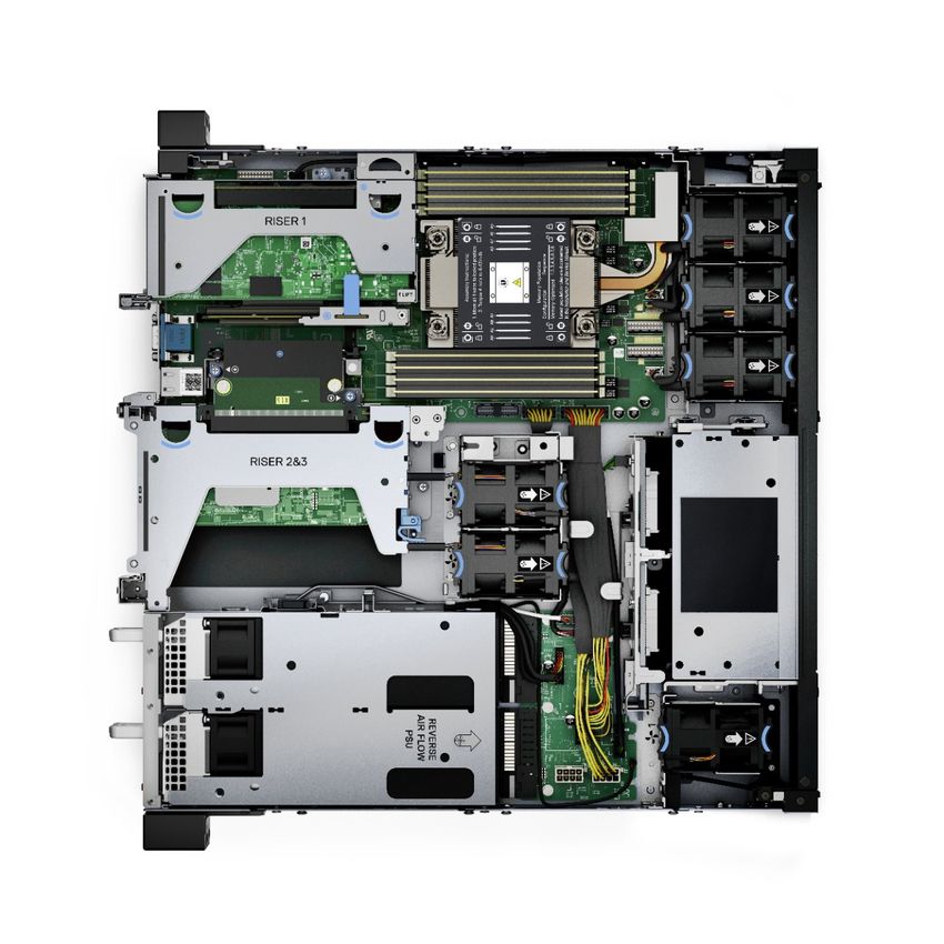
Chassis views and features 15Inside the XR11 front accessed chassis Figure 12. XR11 Front accessed chassis internal view (no bezel) 16 Chassis views and features
Figure 13. XR11 Front accessed chassis internal exploded view (rear to front)

                                                                                Chassis views and features   17
Inside the XR11 rear accessed chassis Figure 14. XR11 Rear accessed chassis internal view (no bezel) 18 Chassis views and features
Figure 15. XR11 Rear accessed chassis internal exploded view (no bezel)

                                                                          Chassis views and features   19
Inside the XR12 front accessed chassis Figure 16. XR12 Front accessed chassis internal front view (no bezel) 20 Chassis views and features
Figure 17. XR12 Front accessed chassis internal exploded view

                                                                Chassis views and features   21
Inside the XR12 rear accessed chassis Figure 18. XR12 Rear accessed chassis internal view (no bezel, no shroud) 22 Chassis views and features
Figure 19. XR12 Rear accessed chassis internal exploded view

Quick Resource Locator (QRL)
There are two types of QRLs on the PowerEdge XR11 and XR12: a generic QRL and a QRL on the Express Service Tag (EST).
The generic QRL for XR11 and XR12 can be found on the System Information Labels (SILs), Getting Started Guide (GSG) and
Installation and Service Manuals. It leads to a webpage with links to product information such as Setup and Service videos,
iDRAC Manual, and other resources that apply to the platform.
The QRL on the EST for XR11 and XR12 is located on the information tag and is unique and specific to that service tag. It
contains the service tag number of the system. The label and the QRL code within it are printed on demand at the L10 factories.
The QRL on the EST also links to a webpage that shows the exact configuration as built for that customer, and the specific
warranty purchased. It is one click away from the same content of generic information that applies to XR11 and XR12 that is
available in the other QRL.

                                                                                         Chassis views and features           23
Figure 20. Generic QRL for XR11 on SIL Figure 21. Generic QRL for XR12 on SIL Figure 22. QRL on EST 24 Chassis views and features
4
                                                                                                       Processor

Topics:
•     Processor features
•     Supported processors for XR11 and XR12

Processor features
The 3 rd Generation Xeon ® Scalable Processors stack is the next generation data center processor offering with the latest
features, increased performance, and incremental memory options. This latest generation Xeon Scalable processor supports
usages from entry designs that are based on Intel Xeon Silver processors to advanced capabilities offered in new Intel Xeon
Platinum processor.
The following lists the features and functions that are in the upcoming 3 rd Generation Intel ® Xeon Scalable Processor offering:
● Faster UPI with 3 Intel Ultra Path Interconnect (Intel UPI) at 11.2 GT/s (supported in gold and platinum options)
● More, faster I/O with PCI Express 4 and up to 64 lanes (per socket) at 16 GT/s

Supported processors for XR11 and XR12
The table below details the list of processors that will be offered at launch. This list is subject to change based on Intel Roadmap
and will be updated accordingly.

Table 3. Processor SKU stack
                                                             Memory
            Clock                                            Speed                      Intel
                      Cache             Thread                            Memory
    Proc    Speed              Cores               Turbo                                Mem        TDP      XR11          XR12
                       (M)                s                               Capacity
            (GHz)                                            (MT/s)                    Enabled

    8351N    2.4        54       36        72      Turbo       2933         6 TB           Y       225    Supported    Supported
                                                                                                    W
    6354      3         39       18        36      Turbo       3200         6 TB           Y       205    Supported    Supported
                                                                                                    W
    6338      2.1       48       32        64      Turbo       3200         6 TB           Y       165    Supported    Supported
     T                                                                                              W
    6338     2.2        48       32        64      Turbo       2666         6 TB           Y       185    Supported    Supported
     N                                                                                              W
    6330     2.2        42       28        56      Turbo       2666         6 TB           Y       165    Supported    Supported
     N                                                                                              W
    6326     2.9        24       16        32      Turbo       3200         6 TB           Y       185    Supported    Supported
                                                                                                    W
    6314U    2.3        48       32        64      Turbo       3200         6 TB           Y       205    Supported    Supported
                                                                                                    W

                                                                                                                Processor        25
Table 3. Processor SKU stack (continued)
Memory
Clock Speed Intel
Cache Thread Memory
Proc Speed Cores Turbo Mem TDP XR11 XR12
(M) s Capacity
(GHz) (MT/s) Enabled
6312U 2.4 36 24 48 Turbo 3200 6 TB Y 185 Supported Supported
W
5320 2.3 30 20 40 Turbo 2933 6 TB Y 150 Supported Supported
T W
5318Y 2.1 36 24 48 Turbo 2933 6 TB Y 165 Supported Supported
W
5318N 2.1 36 24 48 Turbo 2666 6 TB Y 150 Supported Supported
W
5317 3 18 12 24 Turbo 2933 6 TB Y 150 Supported Supported
W
5315Y 3.2 12 8 16 Turbo 2933 6 TB Y 140 Supported Supported
W
4316 2.3 30 20 40 Turbo 2666 6 TB N 150 Supported Supported
W
4314 2.4 24 16 32 Turbo 2666 6 TB Y 135 Supported Supported
W
4310 2.1 18 12 24 Turbo 2666 6 TB N 120 Supported Supported
W
4310T 2.3 15 10 20 Turbo 2666 6 TB N 105 Supported Supported
W
4309 2.8 12 8 16 Turbo 2666 6 TB N 105 Supported Supported
Y W
.
26 Processor5
Memory subsystem
The PowerEdge XR11 and XR12 systems support up to 8 DIMMs, with up to 1024 GB of standard memory and speeds of up to
3200 MT/s.
In addition, the PowerEdge XR11 and XR12 systems support Registered DIMMs (RDIMMs) and Load Reduced DIMMs
(LRDIMMs) which use a buffer to reduce memory loading and provide greater density, allowing for the maximum platform
memory capacity. Unbuffered DIMMs (UDIMMs) and 3DS DIMMs are not supported on both XR11 and XR12. The XR11 and XR12
systems support up to 128 GB of Intel Optane DC persistent memory 200 Series.
Topics:
• Supported memory
Supported memory
The table below lists the memory technologies supported by the platforms XR11 and XR12.
Table 4. Supported DDR4 memory technologies
Feature XR11 and XR12 (DDR4)
DIMM Type RDIMM
LRDIMM
Transfer Speed 3200 MT/s
Voltage 1.2V (DDR4)
The table below lists the supported DDR4 DIMMs for the platforms XR11 and XR12.
Table 5. Memory speed
DIMM Type DIMM Ranking DIMM Capacity DIMM Speed Data width DIMM Volts
(MT/s)
RDIMM 1R 8 GB 3200 8 1.2 V
RDIMM 2R 16 GB 3200 8 1.2 V
RDIMM 2R 32 GB 3200 8 1.2 V
RDIMM 2R 64 GB 3200 4 1.2 V
LRDIMM 4R 128 GB 3200 4 1.2 V
Memory subsystem 276
Storage
Topics:
• Supported drives
• Internal storage configuration matrix for XR11
• Internal storage configuration matrix for XR12
• External storage
Supported drives
The XR11 and XR12 will support several types of drives in these technologies and form factors: 2.5-inch SATA solid-state drives
(SSDs), 2.5-inch SAS SSDs and 2.5-inch NVME SSDs. For a list of the specific drives supported on this platform, please refer to
the Drive And Platform Matrix.
Table 6. Supported drive specifications for XR11 and XR12
Form Factor Type Speed Rotational Speed Capacities
2.5-inch SATA SSD 6 GB N/A 240 GB, 480 GB, 960
GB, 1.92 TB, 3.84 TB
2.5-inch SAS SSD 12 GB N/A 400 GB, 800 GB, 960
GB, 1.6 TB, 1.92 TB,
3.84 TB, 7.68 TB, 15.36
TB
2.5-inch NVMe — N/A 375 GB, 750 GB, 960
GB, 1 TB, 2 TB, 4 TB, 8
TB, 1.6 TB, 3.2 TB, 6.4
TB, 1.92 TB, 3.84 TB,
7.68 TB, 12.8 TB
NOTE: XR11 and XR12 will not support Pin 3 power disable for 12 GB SAS drives as is common in other server designs.
NOTE: XR11 and XR12 will not support NVMe drives with Riser 1A installed.
Internal storage configuration matrix for XR11
Table 7. Internal storage configuration matrix
Config Chassis Base configuration Backplane Storage Controller BOSS Riser
uration orientatio description description controller(s) form factor enabled configuration
n
1 Rear ASSY, CHAS, NAF, x4 2.5 SATA Onboard Onboard SATA Y C0/1: R1B+R2+R3
Access 4HD, 3PCI, 1U, XR11 (only) SATA
(NAF)
2 Rear ASSY, CHAS, NAF, x4 2.5 SAS/ HBA355i Adapter Y C0/1: R1B+R2+R3
Access 4HD, 3PCI, 1U, XR11 SATA
(NAF)
28 StorageTable 7. Internal storage configuration matrix (continued)
Config Chassis Base configuration Backplane Storage Controller BOSS Riser
uration orientatio description description controller(s) form factor enabled configuration
n
3 Rear ASSY, CHAS, NAF, x4 2.5 SAS/ H755 Adapter Y C0/1: R1B+R2+R3
Access 4HD, 3PCI, 1U, XR11 SATA
(NAF)
4 Rear ASSY, CHAS, NAF, x4 2.5 SAS/ H345 Adapter Y C0/1: R1B+R2+R3
Access 4HD, 3PCI, 1U, XR11 SATA
(NAF)
5 Rear ASSY, CHAS, NAF, x4 2.5 NVME S150 Direct Attach Y C0/1: R1B+R2+R3
Access 4HD, 3PCI, 1U, XR11 (only) (SL)
(NAF)
6 Rear ASSY, CHAS, NAF, x4 2.5 NVME H755 Adapter Y C0/1: R1B+R2+R3
Access 4HD, 3PCI, 1U, XR11 (only)
(NAF)
7 Front ASSY, CHAS, RAF, x4 2.5 SATA Onboard Onboard SATA Y C0/1: R1B+R2+R3
Access 4HD, 3PCI, 1U, XR11 (only) SATA C2: R1A+R2+R3
(RAF)
8 Front ASSY, CHAS, RAF, x4 2.5 SAS/ HBA355i Adapter Y C0/1: R1B+R2+R3
Access 4HD, 3PCI, 1U, XR11 SATA
(RAF)
9 Front ASSY, CHAS, RAF, x4 2.5 SAS/ H755 Adapter Y C0/1: R1B+R2+R3
Access 4HD, 3PCI, 1U, XR11 SATA
(RAF)
10 Front ASSY, CHAS, RAF, x4 2.5 SAS/ H345 Adapter Y C0/1: R1B+R2+R3
Access 4HD, 3PCI, 1U, XR11 SATA
(RAF)
11 Front ASSY, CHAS, RAF, x4 2.5 NVME S150 Direct Attach Y C0/1: R1B+R2+R3
Access 4HD, 3PCI, 1U, XR11 (only) (SL)
(RAF)
12 Front ASSY, CHAS, RAF, x4 2.5 NVME H755 Adapter Y C0/1: R1B+R2+R3
Access 4HD, 3PCI, 1U, XR11 (only)
(RAF)
For cable routing information on the different configurations, please refer to the cable matrix on this link: https://
www.delltechnologies.com/sales/en-us/auth/index.htm.
Internal storage configuration matrix for XR12
Table 8. Internal storage configuration matrix
Configu Chassis Base configuration Backplane Storage Controller BOSS Riser
ration orientation description description controller(s) form factor enabled configuration
1 Front ASSY, CHAS, RAF, x6 2.5 SATA Onboard Onboard Y C0: R1B+R2A+R3A
Access 6HD, 3PCI, 2U, XR12 (only) SATA SATA C1: R1B+R2B+R3B
(RAF) C2: R1B+R2B+R3A
C3: R1A+R2A+R3A
C4: R1A+R2B+R3A
2 Front ASSY, CHAS, RAF, x6 2.5 SAS/ HBA355i Adapter Y C0: R1B+R2A+R3A
Access 6HD, 3PCI, 2U, XR12 SATA C1: R1B+R2B+R3B
(RAF) C2: R1B+R2B+R3A
Storage 29Table 8. Internal storage configuration matrix (continued)
Configu Chassis Base configuration Backplane Storage Controller BOSS Riser
ration orientation description description controller(s) form factor enabled configuration
3 Front ASSY, CHAS, RAF, x6 2.5 SAS/ H755 Adapter Y C0: R1B+R2A+R3A
Access 6HD, 3PCI, 2U, XR12 SATA C1: R1B+R2B+R3B
(RAF) C2: R1B+R2B+R3A
4 Front ASSY, CHAS, RAF, x6 2.5 SAS/ H345 Adapter Y C0: R1B+R2A+R3A
Access 6HD, 3PCI, 2U, XR12 SATA C1: R1B+R2B+R3B
(RAF) C2: R1B+R2B+R3A
5 Front ASSY, CHAS, RAF, x4 2.5 NVME S150 + Direct Attach Y C0: R1B+R2A+R3A
Access 6HD, 3PCI, 2U, XR12 + 2.5 SATA Onboard (SL) + C1: R1B+R2B+R3B
(RAF) SATA Onboard C2: R1B+R2B+R3A
SATA
6 Front ASSY, CHAS, RAF, x6 2.5 NVME H755 Adapter Y C0: R1B+R2A+R3A
Access 6HD, 3PCI, 2U, XR12 (only) C1: R1B+R2B+R3B
(RAF) C2: R1B+R2B+R3A
7 Rear ASSY, CHAS, NAF, x6 2.5 SATA Onboard Onboard Y C0: R1B+R2A+R3A
Access 6HD, 3PCI, 2U, XR12 (only) SATA SATA C1: R1B+R2B+R3B
(NAF) C2: R1B+R2B+R3A
8 Rear ASSY, CHAS, NAF, x6 2.5 SAS/ HBA355i Adapter Y C0: R1B+R2A+R3A
Access 6HD, 3PCI, 2U, XR12 SATA C1: R1B+R2B+R3B
(NAF) C2: R1B+R2B+R3A
9 Rear ASSY, CHAS, NAF, x6 2.5 SAS/ H755 Adapter Y C0: R1B+R2A+R3A
Access 6HD, 3PCI, 2U, XR12 SATA C1: R1B+R2B+R3B
(NAF) C2: R1B+R2B+R3A
10 Rear ASSY, CHAS, NAF, x6 2.5 SAS/ H345 Adapter Y C0: R1B+R2A+R3A
Access 6HD, 3PCI, 2U, XR12 SATA C1: R1B+R2B+R3B
(NAF) C2: R1B+R2B+R3A
11 Rear ASSY, CHAS, NAF, x4 2.5 NVME S150 + Direct Attach Y C0: R1B+R2A+R3A
Access 6HD, 3PCI, 2U, XR12 + 2.5 SATA Onboard (SL) + C1: R1B+R2B+R3B
(NAF) SATA Onboard C2: R1B+R2B+R3A
SATA
12 Rear ASSY, CHAS, NAF, x6 2.5 NVME H755 Adapter Y C0: R1B+R2A+R3A
Access 6HD, 3PCI, 2U, XR12 (only) C1: R1B+R2B+R3B
(NAF) C2: R1B+R2B+R3A
For cable routing information on the different configurations, please refer to the cable matrix on this link: https://
www.delltechnologies.com/sales/en-us/auth/index.htm.
External storage
The XR11 and XR12 supports the external storage device types listed in the table below:
Table 9. Supported external storage devices for XR11 and XR12
Device Type Description
External Tape Supports connection to external USB tape products
NAS/IDM appliance software Supports NAS software stack
JBOD Supports connection to 12 Gbps SAS ME484, MD1420 and MD1400
30 Storage7
Expansion cards and expansion card risers
NOTE: A system event entry is logged in the iDRAC Lifecycle Controller if an expansion card riser is not supported or
missing. It does not prevent your system from turning on. However, if a F1/F2 pause occurs with an error message,
see Troubleshooting expansion cards section in the Dell EMC PowerEdge Servers Troubleshooting Guide at www.dell.com/
poweredgemanuals.
Topics:
• Expansion cards and risers for the PowerEdge XR11 system
• Expansion cards and risers for the PowerEdge XR12 system
Expansion cards and risers for the PowerEdge XR11
system
This section provides information on different expansion cards and risers supported for the PowerEdge XR11 system.
Expansion card installation guidelines
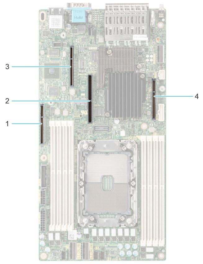
Figure 23. Expansion card slot connectors
1. IO_Riser3 ( Riser 3 connector)
Expansion cards and expansion card risers 312. BOSS S1 card connector
3. IO_Riser2 ( Riser 2 connector)
4. IO_Riser1 (Riser 1 connector)
The following table describes the expansion card riser configurations:
Table 10. Expansion card riser configurations
Configurations Expansion card PCIe Slots Controlling Height Length Slot width
risers processor
Config0. R1B+R2+R3 1 Processor 1 Low profile Half length x8
Rear Accessed 2 Full Height Half length x16
configuration
3 Full Height Half length x16
Config1. R1B+R2+R3 1 Processor 1 Low profile Half length x8
Front Accessed 2 Low profile Half length x16
configuration
3 Full Height Half length x16
NOTE: Riser 2 and 3 are combined in one expansion card riser module.
Figure 24. Riser 1
1. Slot 1, x8, LP-HL (Low Profile - Half Length)
Figure 25. Riser 2 and 3
1. Slot 2, x16, FH-HL (Full Height - Half Length)
2. Slot 3, x16, FH-HL (Full Height - Half Length)
NOTE: The expansion-card slots are not hot-swappable.
The following table provides guidelines for installing expansion cards to ensure proper cooling and mechanical fit. The expansion
cards with the highest priority should be installed first using the slot priority indicated. All the other expansion cards should be
installed in the card priority and slot priority order.
32 Expansion cards and expansion card risersTable 11. Configuration 0: R1B+R2+R3 for Rear Accessed configuration
Card type Slot priority Maximum number of cards
Internal PERC adapter (LP) 1 1
Dell External Adapter (FH) 3, 2 2
GPU (FH) 2, 3 2
Mellanox (NIC: 100Gb) (FH) 2, 3 2
Mellanox (NIC: 25Gb) (FH) 2, 3 2
Broadcom (NIC: 25Gb) (FH) 2, 3 2
Broadcom (NIC: 25Gb) (LP) 1 1
Broadcom (NIC: 10Gb) (FH) 2, 3 2
Broadcom (NIC: 10Gb) (LP) 1 1
Broadcom (NIC: 1Gb) (FH) 3, 2 2
Broadcom (NIC: 1Gb) (LP) 1 1
Intel (NIC: 25Gb) (FH) 2, 3 2
Intel (NIC: 25Gb) (LP) 1 1
Intel (NIC: 10Gb SFP+) (FH) 2 1
Intel (NIC: 10Gb SFP+) (FH) 2 1
Intel (NIC: 10Gb) (FH) (all others 2, 3 2
including V2 of 4 x10 SFP+ and 2 x10
SFP+ cards)
Intel (NIC: 10Gb) (LP) 1 1
Intel (NIC: 1Gb) (FH) 3, 2 2
Intel (NIC: 1Gb) (LP) 1 1
Dell BOSS S1 card Module Integrated slot 1
Table 12. Configuration 1: R1B+R2+R3 for Front Accessed configuration
Card type Slot priority Maximum number of cards
Internal PERC adapter (LP) 1 1
Dell External Adapter (FH) 3, 2 2
GPU (FH) 2, 3 2
Mellanox (NIC: 100Gb) (FH) 2, 3 2
Mellanox (NIC: 25Gb) (FH) 2, 3 2
Broadcom (NIC: 25Gb) (FH) 2, 3 2
Broadcom (NIC: 25Gb) (LP) 1 1
Broadcom (NIC: 10Gb) (FH) 2, 3 2
Broadcom (NIC: 10Gb) (LP) 1 1
Broadcom (NIC: 1Gb) (FH) 3, 2 2
Broadcom (NIC: 1Gb) (LP) 1 1
Intel (NIC: 25Gb) (FH) 2, 3 2
Intel (NIC: 25Gb) (LP) 1 1
Intel (NIC: 10Gb SFP+) (FH) 2 1
Expansion cards and expansion card risers 33Table 12. Configuration 1: R1B+R2+R3 for Front Accessed configuration (continued) Card type Slot priority Maximum number of cards Intel (NIC: 10Gb SFP+) (FH) 2 1 Intel (NIC: 10Gb) (FH) (all others 2, 3 2 including V2 of 4 x10 SFP+ and 2 x10 SFP+ cards) Intel (NIC: 10Gb) (LP) 1 1 Intel (NIC: 1Gb) (FH) 3, 2 2 Intel (NIC: 1Gb) (LP) 1 1 Dell BOSS S1 card Module Integrated slot 1 Expansion cards and risers for the PowerEdge XR12 system This section provides information on different expansion cards and risers supported for the PowerEdge XR12 system. Expansion card installation guidelines Figure 26. Expansion card slot connectors 1. IO_Riser3 ( Riser 3 connector) 2. BOSS (M.2) card connector 3. IO_Riser2 ( Riser 2 connector) 4. IO_Riser1 (Riser 1 connector) The following table describes the expansion card riser configurations: 34 Expansion cards and expansion card risers
Configurations Expansion card PCIe Slots     Controlling   Height          Length           Slot width
               risers                        processor
Config0.             R1B+R2A+R3A      3      Processor 1   Low profile     Half length      x8
                     Rear / Front     2                    Full Height     Full length      x16
                     Accessed
                     configurations   4                    Full Height     Full length      x16

Config1.             R1B+R2B+R3B      3      Processor 1   Low profile     Half length      x8
                     Rear / Front     1, 2                 Full Height     Full length      x8+x8
                     Accessed
                     configurations   4, 5                 Full Height     Full length      x8+x8

Config2.             R1B+R2B+R3A      3      Processor 1   Low profile     Half length      x8
                     Rear / Front     1, 2                 Full Height     Full length      x8+x8
                     Accessed
                     configurations   4                    Full Height     Full length      x16

Figure 27. Riser 1
1. Riser 1, slot 3, x8, LP-HL

Figure 28. Riser 2A
1. Riser 2, slot 2, x16, FH-FL

                                                           Expansion cards and expansion card risers     35
Figure 29. Riser 3A
1. Riser 3, slot 4, x16, FH-FL
NOTE: The expansion-card slots are not hot-swappable.
The following table provides guidelines for installing expansion cards to ensure proper cooling and mechanical fit. The expansion
cards with the highest priority should be installed first using the slot priority indicated. All the other expansion cards should be
installed in the card priority and slot priority order.
Table 13. Configuration 0: R1B+R2A+R3A for Rear / Front Accessed configurations
Card type Slot priority Maximum number of cards
Internal PERC adapter (LP) 3 1
Dell External Adapter (FH) 2, 4 2
GPU (FH) 4, 2 2
Mellanox (NIC: 100Gb) (FH) 4, 2 2
Mellanox (NIC: 25Gb) (FH) 4, 2 2
Broadcom (NIC: 25Gb) (FH) 4, 2 2
Broadcom (NIC: 25Gb) (LP) 3 1
Broadcom (NIC: 10Gb) (FH) 4, 2 2
Broadcom (NIC: 10Gb) (LP) 3 1
Broadcom (NIC: 1Gb) (FH) 4, 2 2
Broadcom (NIC: 1Gb) (LP) 3 1
Intel (NIC: 25Gb) (FH) 4, 2 2
Intel (NIC: 25Gb) (LP) 3 1
Intel (NIC: 4x10Gb SFP+) (FH) 2 1
Intel (NIC: 2x10Gb SFP+) (FH) 2 1
Intel (NIC: 10Gb) (FH) (all others 4, 2 2
including V2 of 4x10 and 2x10 SFP+
cards)
Intel (NIC: 10Gb) (LP) 3 1
Intel (NIC: 1Gb) (FH) 4, 2 2
Intel (NIC: 1Gb) (LP) 3 1
Dell BOSS S1 card Module Integrated slot 1
36 Expansion cards and expansion card risersTable 14. Configuration 1: R1B+R2B+R3B Rear / Front Accessed configurations
Card type Slot priority Maximum number of cards
Internal PERC adapter (LP) 3 1
Dell External Adapter (FH) 1, 2, 4, 5 2
Broadcom (NIC: 25Gb) (FH) 4, 5, 2, 1 4
Broadcom (NIC: 25Gb) (LP) 3 1
Broadcom (NIC: 10Gb) (FH) 4, 5, 2, 1 4
Broadcom (NIC: 10Gb) (LP) 3 1
Broadcom (NIC: 1Gb) (FH) 4, 5, 2, 1 4
Broadcom (NIC: 1Gb) (LP) 3 1
Intel (NIC: 25Gb) (FH) 4, 5, 1, 2 4
Intel (NIC: 25Gb) (LP) 3 1
Intel (NIC: 4x10Gb SFP+) (FH) 1, 2 2
Intel (NIC: 2x10Gb SFP+) (FH) 1, 2 2
Intel (NIC: 10Gb) (FH) (all others 4, 5, 1, 2 4
including V2 of 4x10 and 2x10 SFP+
cards)
Intel (NIC: 10Gb) (LP) 3 1
Intel (NIC: 1Gb) (FH) 4, 5, 1, 2 4
Intel (NIC: 1Gb) (LP) 3 1
Dell BOSS S1 card Module Integrated slot 1
Table 15. Configuration 2: R1B+R2B+R3A for Rear / Front Accessed configuration
Card type Slot priority Maximum number of cards
Internal PERC adapter (LP) 3 1
Dell External Adapter (FH) 2, 1, 4 2
GPU (FH) 4 1
Mellanox (NIC: 100Gb) (FH) 4 1
Mellanox (NIC: 25Gb) (FH) 4 1
Broadcom (NIC: 25Gb) (FH) 4, 1, 2 3
Broadcom (NIC: 25Gb) (LP) 3 1
Broadcom (NIC: 10Gb) (FH) 4, 1, 2 3
Broadcom (NIC: 10Gb) (LP) 3 1
Broadcom (NIC: 1Gb) (FH) 4, 1, 2 3
Broadcom (NIC: 1Gb) (LP) 3 1
Intel (NIC: 25Gb) (FH) 4, 1, 2 3
Intel (NIC: 25Gb) (LP) 3 1
Intel (NIC: 4x10Gb SFP+) (FH) 1, 2 2
Intel (NIC: 2x10Gb SFP+) (FH) 1, 2 2
Expansion cards and expansion card risers 37Table 15. Configuration 2: R1B+R2B+R3A for Rear / Front Accessed configuration (continued)
Card type Slot priority Maximum number of cards
Intel (NIC: 10Gb) (FH) (all others 4, 1, 2 3
including V2 of 4x10 and 2x10 SFP+
cards)
Intel (NIC: 10Gb) (LP) 3 1
Intel (NIC: 1Gb) (FH) 4, 1, 2 3
Intel (NIC: 1Gb) (LP) 3 1 3 1
Dell BOSS S1 card Module Integrated slot 1
CAUTION: Do not install GPUs, network cards, or other PCIe devices on your system that are not validated
and tested by Dell. Damage caused by unauthorized and invalidated hardware installation will null and void the
system warranty.
WARNING: Consumer-Grade GPU should not be installed or used in the Enterprise Server products.
38 Expansion cards and expansion card risers8
Power, thermal, and acoustics
Topics:
• Power for XR11 and XR12
• Thermal for XR11 and XR12
• Acoustics
Power for XR11 and XR12
PowerEdge servers have an extensive collection of sensors that automatically track thermal activity, which helps regulate
temperature thereby reducing server noise and power consumption.
The table below lists the tools and technologies Dell offers to lower power consumption and increase energy efficiency.
Table 16. Power tools and technologies
Feature Description
Power Supply Dell’s PSU portfolio includes intelligent features such as dynamically optimizing efficiency while maintaining
Units (PSU) availability and redundancy. Find additional information in the Power Supply Units section.
portfolio
Tools for right Enterprise Infrastructure Planning Tool (EIPT) is a tool that can help you determine the most efficient
sizing configuration possible. With Dell's EIPT, you can calculate the power consumption of your hardware, power
infrastructure, and storage at a given workload. Learn more at www.dell.com/calc.
Industry Dell’s servers are compliant with all relevant industry certifications and guidelines, including 80 PLUS,
Compliance Climate Savers and ENERGY STAR.
Power PSU power monitoring improvements include:
monitoring ● Dell’s power monitoring accuracy is currently 1%, whereas the industry standard is 5%
accuracy ● More accurate reporting of power
● Better performance under a power cap
Power capping Use Dell's systems management to set the power cap limit for your systems to limit the output of a PSU
and reduce system power consumption. Dell is the first hardware vendor to leverage Intel Node Manager
for circuit-breaker fast capping.
Systems iDRAC9 Datacenter provides server- level management that monitors, reports, and
Management controls power consumption at the processor, memory and system level.
Dell OpenManage Power Center delivers group power management at the rack, row, and
data center level for servers, power distribution units, and uninterruptible power supplies.
Active power Intel Node Manager is an embedded technology that provides individual server-level power reporting
management and power limiting functionality. Dell offers a complete power management solution comprised of Intel
Node Manager accessed through Dell iDRAC9 Datacenter and OpenManage Power Center that allows
policy-based management of power and thermals at the individual server, rack, and data center level. Hot
spare reduces power consumption of redundant power supplies. Thermal control off a speed optimizes the
thermal settings for your environment to reduce fan consumption and lower system power consumption.
Idle power enables Dell servers to run as efficiently when idle as when at full workload.
Fresh Air cooling Please refer to the section ASHRAE A3/A4/Rugged support restriction.
Rack Dell offers some of the industry’s highest- efficiency power infrastructure solutions, including:
infrastructure ● Power distribution units (PDUs)
Power, thermal, and acoustics 39Table 16. Power tools and technologies (continued)
Feature Description
● Uninterruptible power supplies (UPSs)
● Energy Smart containment rack enclosures
Find additional information at: https://www.delltechnologies.com/en-us/servers/power-and-cooling.htm.
Thermal for XR11 and XR12
PowerEdge servers have an extensive collection of sensors that automatically track thermal activity, which helps regulate
temperature thereby reducing server noise and power consumption.
Thermal management of the platform helps delivers high performance for the right amount of cooling to components at the
lowest fan speeds across a wide range of ambient temperatures from 10°C to 35°C (50°F to 86°F) and to extended ambient
temperature ranges (see Environmental Specifications). The benefits to you are lower fan power consumption (lower server
system power and data center power consumption) and greater acoustical versatility.
Acoustics
Acoustical design for XR11 and XR12
The acoustical design of the platform includes the following features:
Dell EMC PowerEdge delivers sound quality and smooth transient response in addition to sound power levels and sound pressure
levels oriented to deployment environments. Sound quality describes how disturbing or pleasing a person finds a sound, as
a function of a variety of psychoacoustical metrics and thresholds. Tone prominence is one such metric. Transient response
refers to how sound changes with time. Sound power level, sound pressure level, and loudness refer to amplitude of sound.
A reference for comparison to sound pressure levels and loudness for familiar noise sources is given in below table. A more
extensive description of Dell EMC PowerEdge acoustical design and metrics is available in the white paper, “Dell Enterprise
Acoustics”.
Table 17. Acoustical reference points and output comparisons
Value measured at your ears Equivalent familiar noise experience
LpA (dBA, re 20 Loudness, sones
µPa)
90 80 Loud concert
75 40 Data center, vacuum cleaner, voice must be elevated to be
heard
60 10 Conversation levels
45 4 Whispering, open office layout, normal living room
35 2 Quiet office
30 1 Quiet library
20 0 Recording studio
PowerEdge acoustics
Dell EMC PowerEdge XR11 and XR12 is a rack-mount server appropriate for general use space (Category 3) and unattended
data center environment (Category 5).
The table below shows the acoustical performance of the XR11 and XR12 for various configurations and acoustical categories.
40 Power, thermal, and acousticsTable 18. Acoustical performance of XR11 and XR12 NAF configurations
XR11 and XR12 NAF Minimum Typical Maximum
configuration
Acoustical Category Category 3 Category 3 Category 5
Processor 1x 10⁵ W 1x 150 W 1x 225 W
Memory 1x 8 GB RDIMM 2x 16 GB RDIMM 4x 32 GB RDIMM; 4x
128 GB Intel Optane
Persistent Memory
200 series DIMM
Storage Front 1x 240 GB SSD 4x 480 GB SSD 4x 7.68 TB NVMe
Storage AUX2 None None BOSS-S1 2x 480 GB
M.2
PCIe Cards None 1x DP 25G 1x H755; 1x DP 25G;
1x T4
PSU 1x 800 W 2x 800 W 2x 1400 W
Table 19. Acoustical performance of XR11 and XR12 RAF configurations
XR11 and XR12 RAF Minimum Typical Maximum
configuration
Acoustical Category Category 3 Category 3 Category 5
Processor 1x 10⁵ W 1x 150 W 1x 225 W
Memory 1x 8 GB RDIMM 2x 16 GB RDIMM 4x 32 GB LRDIMM; 4x
128 GB Intel Optane
Persistent Memory
200 series DIMM
Storage Front 1x 240 GB SSD 4x 480 GB SSD 4x 7.68 TB NVMe
Storage AUX2 None BOSS-S1 2x 480 GB M.2 BOSS-S1 2x 480 GB
M.2
PCIe Cards None 1x DP 25G 1x H755; 1x DP 25G;
1x T4
PSU 1x 1400 W 2x 1400 W 2x 1400 W
Power, thermal, and acoustics 419
Rack, rails, and cable management
Key factors in selecting the proper rails include:
● Identifying the type of rack in which they will be installed
● The spacing between the front and rear mounting flanges of the rack
● The type and location of any equipment mounted in the back of the rack such as power distribution units (PDUs), and the
overall depth of the rack
Reference the Dell EMC Enterprise Systems Rail Sizing and Rack Compatibility Matrix link below for the following information:
● Specific details about rail types and their functionalities
● Rail adjustability ranges for various rack mounting flange types
● Rail depth with and without cable management accessories
● Rack types supported for various rack mounting flange types
https://i.dell.com/sites/csdocuments/Business_solutions_engineering-Docs_Documents/en/rail-rack-matrix.pdf.
Topics:
• Rails information
• Cable Management Arm
• Strain Relief Bar
Rails information
The PowerEdge XR11 and XR12 only supports sliding rails. Due to the short depth of the XR11 and XR12, new sliding rails with
shorter minimum extension have been created.
NOTE: No other rails are compatible with the XR11 and XR12 system.
The sliding rails shown in below image Installing the system in Stab-in sliding rails allow the system to be fully extended out of
the rack for service and are available with the optional cable management arm (CMA) and optional strain relief bar (SRB). There
are 2 types of sliding rails available for the PowerEdge XR11 and XR12 as listed below:
● 2-post / 4-post rack mounting – traditional datacenter rack types with post-to-post depth range 18.5-inch – 29.5-inch [470
mm – 750 mm].
● Transit case mounting for mobility – The rugged MIL 901E performance is only certified in the Pelican custom rack
25-036329-01-DE2412-05/24/05.
The PowerEdge XR11 and XR12 sliding rails are stab-in style. A "stab-in" design means that the inner (chassis) rail members
must first be attached to the sides of the system and then inserted into the outer (cabinet) members installed in the rack. 2U
systems require a two-person lift.
Figure 30. Installing the system in stab-in sliding rails
42 Rack, rails, and cable managementDell PowerEdge XR11 and XR12 sliding rails overview:
● Support for tool-less installation in 19-inch EIA-310-E compliant square or unthreaded round hole racks including all
generations of Dell racks. Also supports tooled installation in threaded round hole racks.
● Supports Stab-in installation of the chassis to the rails.
● Support full extension of the system out of the rack to allow serviceability of key internal components.
● Supports for optional cable management arm (CMA) and strain relief bar (SRB).
Sliding rails in 2-post rack
The sliding rails for XR11 and XR12 provide support for 2-post racks with 19-inch EIA-310-E compliant square, round, or threaded
round mounting holes. Adapter brackets and screws (included in the rail kit) are necessary to mount the XR11 and XR12 into
2-post racks either in flush-mount or center-mount positions.
NOTE: Two-post racks are not supported in the rugged environment.
Figure 31. XR11 Mounted in sliding rails in 2-post center-mount configuration
Rack, rails, and cable management 43Figure 32. XR12 Mounted in sliding rails in 2-post center-mount configuration Sliding rails in 4-post rack The sliding rails for XR11 and XR12 provide tool-less support for 4-post racks with 19-inch EIA-310-E compliant square or unthreaded round mounting holes including all generations of Dell racks when the post-to-post rack depth is between 18.5-inch – 29.5-inch [470 mm – 750 mm]. There are additional screws included in the rail kit to tightly secure the rails to the 4-post rack if desired. Figure 33. XR11 and XR12 stab-in sliding rail mounting interface for 4-post round or square hole racks 44 Rack, rails, and cable management
Figure 34. XR11 mounted in sliding rails with the CMA in 4-post rack

Figure 35. XR12 mounted in sliding rails with the CMA in 4-post rack

                                                                       Rack, rails, and cable management   45
Sliding rails in Pelican transit case
For transit cases, a specific type of rail has been designed. It is orderable from Dell and is compatible with the Pelican custom
rack. It has a 20-inch post spacing with post-to-post rack depth is between 16.8-inch - 22-inch [428 mm - 558 mm].
Dell only certifies XR11 and XR12 compliance for MIL 901E performance in this Pelican case.
NOTE: The part number for the Pelican case is 25-036329-01-DE2412-05/24/05.
Figure 36. XR11 and XR12 Transit case rails in Pelican case frame
Cable Management Arm
The optional cable management arm (CMA) for the XR11 and XR12 organizes and secures the cords and cables exiting the back
of the server and unfolds to allow the server to extend out of the rack without having to detach the cables. Some key features
of the CMA include:
● Large U-shaped baskets to support dense cable loads
● Open vent pattern for optimal airflow
● Can be mounted on either side by simply swinging the spring-loaded brackets from one side to the other
● Utilizes hook-and-loop straps rather than plastic tie wraps to eliminate the risk of cable damage during cycling
● Includes a low-profile fixed tray to both support and retain the CMA in its fully closed position
● Both the CMA and the tray mount without the use of tools via simple and intuitive snap-in designs
The CMA can be mounted to either side of the sliding rails without the use of tools or the need for conversion, but it is
recommended that it be mounted on the side opposite to the power supplies to allow easier access to the power supplies for
service or replacement.
46 Rack, rails, and cable managementYou can also read