Dell EMC PowerStore: Clustering and High Availability - Abstract
←
→
Page content transcription
If your browser does not render page correctly, please read the page content below

Technical White Paper

 Dell EMC PowerStore: Clustering and High
 Availability
                         Abstract
                         This white paper provides an overview of Dell EMC™ PowerStore™ clustering
                         technology along with the highly available features of the platform.

                         April 2021

H18157.2
Revisions

Revisions
                 Date                       Description
                 April 2020                 Initial release: PowerStoreOS 1.0

                 September 2020             Updates to high availability section; other minor updates

                 April 2021                 PowerStoreOS 2.0 updates

Acknowledgments
               Author: Jonathan Tang

The information in this publication is provided “as is.” Dell Inc. makes no representations or warranties of any kind with respect to the information in this
publication, and specifically disclaims implied warranties of merchantability or fitness for a particular purpose.

Use, copying, and distribution of any software described in this publication requires an applicable software license.

This document may contain certain words that are not consistent with Dell's current language guidelines. Dell plans to update the document over
subsequent future releases to revise these words accordingly.

This document may contain language from third party content that is not under Dell's control and is not consistent with Dell's current guidelines for Dell's
own content. When such third party content is updated by the relevant third parties, this document will be revised accordingly.

Copyright © 2020–2021 Dell Inc. or its subsidiaries. All Rights Reserved. Dell Technologies, Dell, EMC, Dell EMC and other trademarks are trademarks
of Dell Inc. or its subsidiaries. Other trademarks may be trademarks of their respective owners. [9/17/2021] [Technical White Paper] [H18157.2]

2         Dell EMC PowerStore: Clustering and High Availability | H18157.2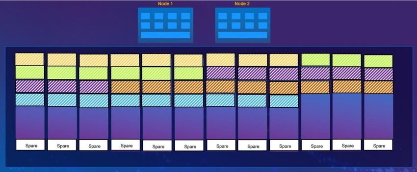
Table of contents

Table of contents
    Revisions.............................................................................................................................................................................2
    Acknowledgments ...............................................................................................................................................................2
    Executive summary.............................................................................................................................................................5
    Audience .............................................................................................................................................................................5
    1     Introduction ...................................................................................................................................................................6
          1.1      PowerStore product overview.............................................................................................................................6
          1.2      Terminology ........................................................................................................................................................6
    2     Clustering .....................................................................................................................................................................8
          2.1      Requirements .....................................................................................................................................................8
          2.2      Primary appliance ...............................................................................................................................................9
          2.3      Initial configuration ............................................................................................................................................10
          2.3.1 PowerStore T Cluster .......................................................................................................................................10
          2.3.2 PowerStore X Cluster .......................................................................................................................................12
          2.4      Add appliance ...................................................................................................................................................12
          2.4.1 Selecting the appliance ....................................................................................................................................13
          2.4.2 Configuring IP addresses .................................................................................................................................13
          2.4.3 Review the job ..................................................................................................................................................15
          2.5      Remove appliance ............................................................................................................................................15
          2.5.1 PowerStore Manager ........................................................................................................................................16
          2.5.2 Service script ....................................................................................................................................................17
          2.6      VMware integration ...........................................................................................................................................17
          2.7      Resource balancer ...........................................................................................................................................18
          2.7.1 Initial placement of data ....................................................................................................................................18
          2.7.2 Volume groups..................................................................................................................................................18
          2.7.3 Migration overview ............................................................................................................................................19
          2.7.4 Manual migration ..............................................................................................................................................20
          2.7.5 Assisted migration ............................................................................................................................................21
          2.7.6 Appliance space evacuation .............................................................................................................................22
          2.7.7 Migration states ................................................................................................................................................23
          2.7.8 Capacity forecasting .........................................................................................................................................24
    3     High availability...........................................................................................................................................................25
          3.1      Hardware redundancy ......................................................................................................................................25
          3.1.1 Management software ......................................................................................................................................26
          3.1.2 System bond .....................................................................................................................................................27

3            Dell EMC PowerStore: Clustering and High Availability | H18157.2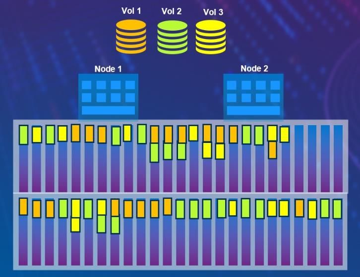
Table of contents

        3.2      Dynamic Resiliency Engine (DRE) ...................................................................................................................27
        3.2.1 Overview ...........................................................................................................................................................28
        3.2.2 Distributed Sparing ...........................................................................................................................................28
        3.2.3 Resiliency Sets .................................................................................................................................................29
        3.3      Block storage ....................................................................................................................................................31
        3.3.1 iSCSI configuration ...........................................................................................................................................32
        3.3.2 Fibre Channel configuration .............................................................................................................................35
        3.3.3 Block example ..................................................................................................................................................36
        3.4      File storage .......................................................................................................................................................37
        3.5      VMware integration ...........................................................................................................................................38
        3.5.1 Controller VMs ..................................................................................................................................................38
        3.5.2 vSphere HA ......................................................................................................................................................38
        3.5.3 vCenter connection ...........................................................................................................................................38
        3.6      Replication ........................................................................................................................................................39
        3.7      Platform high availability ...................................................................................................................................39
        3.8      Cluster high availability .....................................................................................................................................39
        3.8.1 Cluster quorum .................................................................................................................................................40
        3.8.2 Cluster IP ..........................................................................................................................................................41
        3.8.3 Global storage IP ..............................................................................................................................................41
    4   Conclusion ..................................................................................................................................................................42
    A   Technical support and resources ...............................................................................................................................43

4          Dell EMC PowerStore: Clustering and High Availability | H18157.2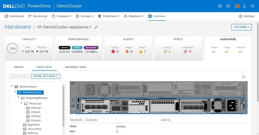
Executive summary

Executive summary
           This white paper discusses the redundant hardware and high-availability features that are available on Dell
           EMC™ PowerStore™. PowerStore features fully redundant hardware and includes several high-availability
           features. These features are designed to withstand component failures within the system itself and in the
           environment, such as network or power failures. If an individual component fails, the storage system can
           remain online and continue to serve data. The system can also withstand multiple failures if they occur in
           separate component sets. After the administrator is alerted about the failure, they can order and replace the
           failed component without any impact.

Audience
           This document is intended for IT administrators, storage architects, partners, and Dell Technologies™
           employees. This audience also includes any individuals who may evaluate, acquire, manage, operate, or
           design a Dell EMC networked storage environment using PowerStore systems.

5      Dell EMC PowerStore: Clustering and High Availability | H18157.2
Introduction

1              Introduction
               Having constant access to data is a critical component in any modern business. If data becomes inaccessible,
               business operations may be impacted and can potentially cause revenue loss. Because of this, IT
               administrators are tasked with ensuring that every component in the data center has no single point of failure.
               This white paper details how to cluster PowerStore systems and describes the high availability features that
               are available on the PowerStore system, which is designed for 99.9999% availability.1

1.1            PowerStore product overview
               PowerStore achieves new levels of value, flexibility, and simplicity in storage. It uses a container-based
               microservices architecture, advanced storage technologies, and integrated machine learning to unlock the
               power of your data. PowerStore is a versatile platform with a performance-centric design that delivers scale-
               up and scale-out capabilities, always-on data reduction, and support for next-generation media.

               PowerStore brings the simplicity of the public cloud to on-premises infrastructure, streamlining operations with
               an integrated machine learning engine and seamless automation. It also offers predictive analytics to easily
               monitor, analyze, and troubleshoot the environment. PowerStore is highly adaptable, providing the flexibility to
               host specialized workloads directly on the appliance and modernize infrastructure without disruption. It also
               offers investment protection through flexible payment solutions.

1.2            Terminology
               The following terms that are used with PowerStore:

               Appliance: Solution containing the base enclosure and any attached expansion enclosures.

               Base enclosure: Used to reference the enclosure containing both Nodes (Node A and Node B) and 25x
               NVMe drive slots.

               Cluster: One or more appliances in a single grouping and management interface. Clusters are expandable by
               adding more appliances to the existing cluster, up to the allowed amount for a cluster.

               Expansion enclosure: Enclosures that can be attached to a base enclosure to provide additional storage.

               Fibre Channel (FC) protocol: A protocol used to perform Internet Protocol (IP) and Small Computer Systems
               Interface (SCSI) commands over a Fibre Channel network.

               File system: A storage resource that can be accessed through file-sharing protocols such as SMB or NFS.

               Internet SCSI (iSCSI): Provides a mechanism for accessing block-level data storage over network
               connections.

               Intracluster Management (ICM) Network: An internal management network that provides continuous
               management connectivity between appliances in the PowerStore cluster.

               Intracluster Data (ICD) Network: An internal network that provides continuous storage connectivity between
               appliances in the PowerStore cluster.

6       Dell EMC PowerStore: Clustering and High Availability | H18157.2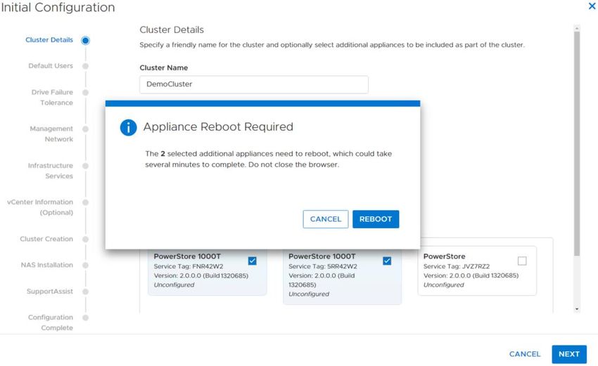
Introduction

               Network-attached storage (NAS) server: A virtualized network-attached storage server that uses the SMB,
               NFS, FTP, and SFTP protocols to catalog, organize, and transfer files within file system shares and exports.
               A NAS server, the basis for multitenancy, must be created before you can create file-level storage resources.
               NAS servers are responsible for the configuration parameters on the set of file systems that it serves.

               Network File System (NFS): An access protocol that allows data access from Linux®/UNIX® hosts on a
               network.

               Node: Component within an appliance that contains processors and memory. Each appliance consists of two
               nodes.

               PowerStore Manager: An HTML5 user interface used to manage PowerStore systems.

               PowerStore T model: Container-based storage system that is running on purpose-built hardware. This
               storage system supports unified (block and file) workloads, or block-optimized workloads.

               PowerStore X model: Container-based storage system that is running inside a virtual machine that is
               deployed on a VMware hypervisor. In addition to the block-optimized workloads that this storage system
               offers, it also allows users to deploy applications to be deployed directly on the array.

               Representational State Transfer (REST) API: A set of resources (objects), operations, and attributes that
               provide interactive, scripted, and programmatic management control of the PowerStore cluster.

               Server Message Block (SMB): A network file sharing protocol, sometimes referred to as CIFS, used by
               Microsoft® Windows® environments. SMB is used to provide access to files and folders from Windows hosts
               on a network.

               Snapshot: A point-in-time view of data stored on a storage resource. A user can recover files from a
               snapshot, restore a storage resource from a snapshot, or clone the snapshot to provide access to a host.

               Storage Policy Based Management (SPBM): Using policies to control storage-related capabilities for a VM
               and ensure compliance throughout its life cycle.

               PowerStore Command Line Interface (PSTCLI): An interface that allows a user to perform tasks on the
               storage system by typing commands instead of using the UI.

               VMware vSphere Virtual Volumes (vVols): A VMware storage framework which allows VM data to be
               stored on individual Virtual Volumes. This ability allows for data services to be applied at a VM-level of
               granularity and according to SPBM. Virtual Volumes can also refer to the individual storage objects that are
               used to enable this functionality.

               vSphere API for Array Integration (VAAI): A VMware API that improves ESXi host utilization by offloading
               storage-related tasks to the storage system.

               vSphere API for Storage Awareness (VASA): A VMware vendor-neutral API that enables vSphere to
               determine the capabilities of a storage system. This feature requires a VASA provider on the storage system
               for communication.

               Volume: A block-level storage device that can be shared out using a protocol such as iSCSI or Fibre
               Channel.

7       Dell EMC PowerStore: Clustering and High Availability | H18157.2
Clustering

2            Clustering
             Every PowerStore appliance is deployed into a PowerStore cluster. There is a minimum of one PowerStore
             appliance and a maximum of four PowerStore appliances that can be configured into the cluster. A user can
             create a cluster made up of all PowerStore T model appliances or all PowerStore X appliances, but
             appliances cannot be mixed with both models in the same cluster. When a multi-appliance cluster is
             deployed, this task can be performed during the initial configuration process or appliances can be added to an
             existing cluster. PowerStore clusters can be scaled down by removing appliances from an existing cluster.

             Clustering PowerStore appliances can provide many benefits:

                 •   Easy scale out to increase CPU, memory, storage capacity, and front-end connectivity
                 •   Independent scaling of storage and compute resources
                 •   Centralized management for multi-appliance cluster
                 •   Automated orchestration for host connectivity
                 •   Increased resiliency and fault tolerance

             Consider the example in Figure 1, users can scale out appliances with different model numbers to create a
             four-appliance cluster. In addition to the scale-out benefit, each appliance can scale-up with different numbers
             of expansion enclosures. For example, each appliance that is shown in Figure 1 has different number of
             expansion enclosures attached. Finally, each appliance in the cluster can have different media types. For
             example, the PowerStore 1000T model could have NVMe SCM drives, while the PowerStore 3000T, 5000T,
             and 7000T models could have NVMe SSD drives. This flexible scale-out and scale-up deployment gives
             customers the ability to grow their clusters with no dependence on the model number, drive count, or even
             drive type.

                         Multi-appliance cluster

2.1          Requirements
             Ensure that the PowerStore systems are cabled correctly by referencing the Dell EMC PowerStore Quick
             Start Guide on the PowerStore Info Hub. Each node in every appliance that is a part of a PowerStore cluster
             must communicate to other nodes through the bonded ports (see Figure 2). The network that allows the
             nodes to communicate to each other is an internal network named the Intracluster Management (ICM) and

8      Dell EMC PowerStore: Clustering and High Availability | H18157.2
Clustering

             Intracluster Data (ICD) networks. In PowerStore, the ICM and ICD networks communicates through the
             network with untagged VLAN network packets that have auto-generated IPv6 addresses. All appliances in the
             cluster should be in the same rack or multiple racks in the same data center. If PowerStore appliances span
             multiple switches, ensure that the untagged network (or native VLAN) is configured on the switch ports and
             are shared across the switches. Deploying a cluster in different buildings but on the same campus, also
             known as stretched clusters, is not supported.
                                                                                                  1                            0

                                                                                                                                                                                          x4
                                                                                                                                                                                      B
                  B                                                                                                                                                                                     3       2   1   0           B
                                                                               3          2   1   0            3       2   1       0
                                                                                                                                                                                               A

                                                                                                                                                                1GbE

                                                                                                                                                                                               12

                                                                                                                                                                                                                            10GbE
                                                                                                                                                                                               A

                                                                                                                                           SS
                                           2200W                                                                                                                                  B                         3   2   1   0

                                                                                                                                                                                                    0
                                                                                                                                       1

                                                                                                                                                                           1GbE
                                                                            1GbE
                                                                                                                                                                                                        2200W

                                                                                                           1
                              0    1   2      3                         B
                                                      0
                      10GbE

                                                          A

                                                                                                      SS
                                                                                   1GbE
                                                          12

                              0   1    2          3       A                                                    0       1                        0       1
                                                                                                                           2       3                        2          3
                  A                                                 B                                                                                                                                                               A
                                                               x4

                                                                                                                   0                                1

                                  Back view of PowerStore appliance

2.2          Primary appliance
             Each cluster has a primary appliance which is the first appliance that is selected during the initial
             configuration. For PowerStore T model appliances, the primary appliance can be configured in unified mode
             or block-optimized mode during the initial configuration process. Starting in PowerStoreOS 2.0, the primary
             appliance is automatically selected by the operating system for Block-optimized clusters.

             Figure 3 shows an example of an appliance with unified mode selected. File services only run on the primary
             appliance of a unified cluster. If an appliance uses file services, ensure that the Storage Configuration field
             has Unified mode selected. If an appliance only uses block workloads such as iSCSI or FC, ensure that the
             Storage Configuration has Block Optimized mode selected.

             Note: An appliance cannot change its configuration type (Unified or Block Optimized) after the cluster has
             been configured.

                                  Unified storage configuration

9      Dell EMC PowerStore: Clustering and High Availability | H18157.2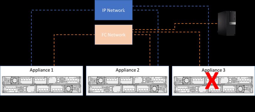
Clustering

2.3          Initial configuration
             When completing the Initial Configuration Wizard, the PowerStore system scans for other appliances on the
             network. If there are multiple types of PowerStore T model or PowerStore X model appliances on the network,
             the wizard only displays the PowerStore model that is initially selected. For example, if a PowerStore T model
             is selected as the primary appliance, only PowerStore T model appliances will be displayed. To add extra
             appliances to the cluster, click the Select Additional Appliances button. The resulting view shows all
             available appliances that are eligible to be a part of the cluster.

             Figure 4 shows an example of a selecting a multi-appliance cluster. There are no PowerStore X model
             appliances available for selection because a PowerStore T model appliance was selected as the primary
             appliance. For more information about the discovery process, see the document Dell EMC PowerStore:
             Introduction to the Platform on Dell.com/StorageResources.

                         Multi-appliance selection

2.3.1        PowerStore T Cluster
             Below are some general guidelines to consider when creating a multi-appliance PowerStore T cluster for the
             first time. Unified mode and block-optimized mode are detailed in the following sections of the white paper.

                 •   The final cluster size cannot exceed four appliances.
                 •   The user can only select healthy and uninitialized appliances.
                 •   Each appliance is configured synchronously starting with the primary appliance.
                 •   Only the primary appliance can be in unified mode if selected.
                 •   All additional appliances are automatically rebooted into a block-optimized configuration when added
                     into a cluster.
                 •   The appliances must be able to communicate with each other with untagged VLAN and IPv6
                     addresses on the bonded interfaces of the PowerStore system.

10      Dell EMC PowerStore: Clustering and High Availability | H18157.2
Clustering
• The system bonds of all appliances should be on the same native VLAN.
2.3.1.1 Unified cluster
When setting up a cluster for the first time, determine if the cluster will use file services. If a decision has not
been made, it is recommended to deploy a unified cluster to provide the most flexibility in the future. As
mentioned in section 2.2, file services only run on the primary appliance of a unified cluster. If other
appliances are configured in the cluster, those appliances are deployed in a block-optimized configuration.
Figure 5 shows an example of creating a multi-appliance cluster. The primary appliance is set to unified and
the other appliances are rebooted into a block-optimized configuration.
Reboot non-primary appliances to block optimized configuration
2.3.1.2 Block-optimized cluster
If file services are not used, a cluster can be configured to be block optimized to deliver the highest possible
block performance. Figure 6 shows an example of a multi-appliance cluster that will be configured as block
optimized. The primary appliance is now set to block optimized configuration. This means that all the
appliances that are selected must be automatically rebooted into a block-optimized configuration before the
cluster can be configured.
Note: A cluster cannot change configuration type (unified or block optimized) after the cluster has been
configured.
11 Dell EMC PowerStore: Clustering and High Availability | H18157.2Clustering
Reboot all appliances in a block-optimized cluster
2.3.2 PowerStore X Cluster
Below are some general guidelines to consider when creating a multi-appliance PowerStore T cluster for the
first time. Unified mode and block-optimized mode are detailed in the following sections of the white paper.
• The final cluster size cannot exceed four appliances.
• The user can only select healthy and uninitialized appliances.
• Each appliance is configured synchronously starting with the primary appliance.
• The appliances must be able to communicate with each other with untagged VLAN and IPv6
addresses on the bonded interfaces of the PowerStore system.
• The first two ports of the 4-port card of all appliances should be on the same native VLAN.
2.4 Add appliance
PowerStore allows scaling a cluster, scaling up and scaling out independently. To add more capacity, scale
up by adding expansion enclosures. To add compute, memory, and connectivity, scale out by adding
appliances to an existing cluster. Adding an appliance is supported using the PowerStore Manager, REST
API, and PSTCLI.
General guidelines to consider when adding appliances to an existing cluster:
• Final cluster size cannot exceed four appliances
• Can only add uninitialized appliances
• Can only add one at a time
• New appliance as well as the existing cluster must be in a healthy state
• All appliances must be able to communicate with each other using untagged VLAN and IPv6
addresses on the system bond of the PowerStore system
• The system bonds of all appliances should be on the same native VLAN
12 Dell EMC PowerStore: Clustering and High Availability | H18157.2Clustering
2.4.1 Selecting the appliance
PowerStore Manager simplifies adding an appliance into an existing cluster. Figure 7 shows an example of
adding an appliance into an existing cluster. To add the appliance, go to the Hardware page and click the
Add button. This action presents the available unconfigured appliances that can be added. If a PowerStore T
model appliance is being added to the cluster, the appliance will automatically reboot into the block-optimized
configuration.
How to add an appliance
2.4.2 Configuring IP addresses
After an appliance has been selected, extra IP addresses must be added to the cluster if none are available.
There are two methods for adding additional IP addresses. For example, Figure 8 and Figure 9 show how to
add IP addresses during the Add appliance workflow. In this example, a single PowerStore T model
appliance is being added to the cluster. For cluster expansion, three additional management IP addresses
and two storage IP addresses (not pictured below) must be added to expand the cluster. Users can simply
click Add Network IPs to supply new IP addresses for their management or storage networks.
How to add IPs from the Add Appliance Wizard
13 Dell EMC PowerStore: Clustering and High Availability | H18157.2Clustering
Adding Management IPs
The alternative method for adding IP addresses is to go to the Settings > Networking > Network IPs. Figure
10 shows an example of this page. A user can reserve a range of extra IP addresses where the PowerStore
system may initially only use a small set of those IPs.
How to add IPs from the Settings Page
2.4.2.1 Validate network configuration
In the Add Appliance > Summary page, perform a network validation check before starting the Add
Appliance job. Warnings or errors may display after the network validation check is performed. It is
recommended to address warnings before beginning a cluster creation, but the warnings can be bypassed.
However, if there are any errors, it is required to correct them before starting the Add Appliance job. If the
errors are not addressed, users are blocked from starting a cluster-creation job. Figure 11 shows an example
of the Summary page and the network can be validated.
14 Dell EMC PowerStore: Clustering and High Availability | H18157.2Clustering
Add appliance network validation
2.4.3 Review the job
Once the Add Appliance wizard is completed, a new job is created. To see more details about the job, click
the Jobs icon in the top-right area of PowerStore Manager. Figure 12 shows an example of an Add Appliance
job that is being run in the background. This job allows other tasks to be performed in PowerStore Manager
while the Add Appliance job is running.
Add appliance job
2.5 Remove appliance
Both the PowerStore T and PowerStore X model clusters can be scaled down by removing individual
appliances from the cluster. Removing an appliance from a cluster requires careful planning and
consideration. Before starting this process, storage resources can be automatically or manually migrated off
the appliance. Any remaining storage resources can be manually deleted before removing the appliance and
then removing the appliance from the cluster. After an appliance is removed from the cluster, the appliance is
reverted to the original factory settings.
15 Dell EMC PowerStore: Clustering and High Availability | H18157.2Clustering
When removing an appliance from the cluster, there are different steps that users need to be aware of
depending on the model of the PowerStore appliance. Table 1 shows the high-level steps for removing a
PowerStore T model appliance from the cluster. However for the PowerStore X model appliance, users must
migrate storage resources as well as Virtual Machines (VMs) to other appliances in the cluster as shown in
Table 2. For detailed steps regarding removing a PowerStore X model appliance, reference the PowerStore
Manager Online Help.
Table 1 High level steps of removing a PowerStore T model appliance
Entity Operation
PowerStore Manager Migrate storage resources to other appliances in the cluster
PowerStore Manager Disable support notifications
PowerStore Manager Remove the appliance from the cluster
Table 2 High level steps of removing a PowerStore X model appliance
Entity Operation
PowerStore Manager Migrate storage resources to other appliances in the cluster
PowerStore Manager Disable support notifications
PowerStore Manager Identify the non-primary node
vSphere Web Client vMotion VMs located on the non-primary node to other appliances on the
cluster
vSphere Web Client Enable maintenance mode of the non-primary node
vSphere Web Client Remove the non-primary node from the ESXi cluster
vSphere Web Client Exit maintenance mode of the non-primary node
vSphere Web Client Power on the Controller VM
vSphere Web Client & Repeat the steps above for the primary node
PowerStore Manager
vSphere Web Client & Remove the appliance from the cluster
PowerStore Manager
2.5.1 PowerStore Manager
Starting in PowerStoreOS 2.0, the recommended method to remove an appliance from a cluster is now
available from the PowerStore Manager. This operation is performed with a two-step process. The first step of
the procedure is to migrate storage resources off the appliance that is about to be removed. This procedure
can be easily performed from PowerStore Manager. Starting from the Hardware page, a user can select the
appliance that is about to be removed, then select More Actions > Migrate. A user will be guided through a
wizard-based workflow to automatically move storage resources to other appliances in the cluster. Additional
information regarding appliance space evacuation will be discussed later in this document.
The second step is to remove the appliance from the cluster. As shown in Figure 13, a user can start from the
Hardware page, select the appliance that is about to be removed and then select Remove.
16 Dell EMC PowerStore: Clustering and High Availability | H18157.2Clustering
Remove appliance
2.5.2 Service script
For users that are not running PowerStoreOS 2.0 and later, see the following guidelines and workflow for
running the service script to remove an appliance from a cluster:
• Notify all users to avoid creating storage resources or virtual machines while this operation is in progress.
• Run the svc_remove_appliance script and note the storage resources and workloads on the appliance.
• Using the prompts from the script, review and stop the scheduler and automated storage placement,
allowing all active jobs to complete.
• Migrate storage resources or virtual machines to another appliance in the cluster.
• Cycle through the prompts in the script to review and ensure that there are no more active workloads on
the appliance.
• Continue with the prompts and confirm to start removal of the appliance.
Note: The svc_remove_appliance service script does not automatically migrate storage resources off the
appliance that is being removed.
2.6 VMware integration
PowerStore T models and PowerStore X models offer deep integration with VMware vSphere such as VAAI
and VASA support, event notifications, snapshot management, storage containers for virtual volumes (vVols),
and virtual machine discovery and monitoring in PowerStore Manager. By default, when a PowerStore T
model or PowerStore X model is initialized, a storage container is automatically created on the appliance.
Storage containers are used to present vVol storage from PowerStore to vSphere. vSphere then mounts the
storage container as a vVol datastore and makes it available for VM storage. This vVol datastore is then
accessible by internal ESXi nodes or external ESXi hosts. If an administrator has a multi-appliance cluster,
the total capacity of a storage container spans the aggregation of all appliances within the cluster. It is
important to note for PowerStore X model appliances, the cluster Distributed Resource Scheduler (DRS) is
set to partially automated mode. Since the appliance is optimized for and expects this configuration, changing
17 Dell EMC PowerStore: Clustering and High Availability | H18157.2Clustering
these settings is not supported. For more information about VMware Integration with PowerStore, see the
document Dell EMC PowerStore: Virtualization Integration on Dell.com/StorageResources.
2.7 Resource balancer
In the modern data center, administrators must be quick and agile to support mission-critical applications.
PowerStore offers an intelligent analytical engine that is built into the PowerStore operating system. This
engine offers many benefits such as helping administrators make decisions that are based on initial
placement of data. It also assists with volume migrations or storage expansions that are based on analytics
and capacity forecasting.
2.7.1 Initial placement of data
When storage administrators are creating storage resources, the resource balancer can provide many
benefits. For example, when a multi-appliance cluster is deployed, the resource balancer intelligently and
automatically places newly created volumes on different appliances in the cluster. This placement is based on
which appliance has the most unused capacity. If choosing to override the decision of automatic placement,
there is an option to manually select which appliance to place the volume.
Figure 14 shows an example of a volume that will be placed automatically on a specific appliance. It is
important to note that when volumes or volume groups are created, they are only placed on a single
appliance and do not span multiple appliances in the cluster. After these storage resources are created, they
do not move until migrated manually to another appliance in the cluster. Migration of storage resources within
a cluster is discussed in the following sections of this paper.
Automatic Placement of volumes or manual assignment
2.7.2 Volume groups
In PowerStore, when volume groups are created for the first time, all corresponding members in the volume
group are placed on the same appliance. If a user has existing volumes, there may be situations in which
18 Dell EMC PowerStore: Clustering and High Availability | H18157.2Clustering
these volumes could have been automatically placed on different appliances in the cluster. In these situations,
the storage resources must be migrated manually to a single appliance before placing them into a volume
group.
2.7.3 Migration overview
After a volume or volume group has been created on an appliance, capacity and demand may change over
time. PowerStore supports moving a volume, volume group, or vVol to another appliance within the cluster.
This operation can be performed with a Manual Migration, Assisted Migration, or Appliance Space Evacuation
within a PowerStore cluster by using PowerStore Manager, REST API, and PSTCLI. These methods will be
detailed in the next sections of this paper. For additional information regarding vVol migrations, reference the
Dell EMC PowerStore: Virtualization Integration paper on Dell.com/StorageResources.
Before the start of a migration job, the administrator must verify the following steps:
• If applicable, verify or setup zoning on FC switches between the host, source appliance, and
destination appliance.
• Ensure that the host has connectivity to the source and destination appliances with iSCSI or FC
protocol.
• The host object in PowerStore Manager shows initiators going to the source and destination
appliances.
• From the host, perform a rescan of the storage object that will be migrated.
Once the above steps have been verified, a migration job can be started which is non-disruptive and
transparent to the host. Although not visible to the end user, the storage resource is transferred to the new
appliance within the cluster by leveraging asynchronous replication technology. It is important to note that
when the storage resource is being moved over to the destination, all the associated storage objects such as
snapshots and clones that are tied to the storage resource will be moved over to the destination as well. After
the data transfer is complete, the host will switch paths automatically to the destination appliance and the
migration job is complete.
Figure 15 shows an example of a multi-appliance cluster that is made up of four appliances. In this example,
a user would like to move a storage resource off the PowerStore 1000T model over to a PowerStore 5000T
model. The host may have connectivity to the two appliances by using iSCSI or FC protocols. Notice however
that the PowerStore 3000T and 7000T models do not have host connectivity. This means that the storage
resource would not be able to migrate over to those appliances until host connectivity is established.
19 Dell EMC PowerStore: Clustering and High Availability | H18157.2Clustering
Volume migration example
2.7.4 Manual migration
PowerStore supports moving storage resources such as a volume, volume group, or vVol to another
appliance within the cluster. Before moving the storage resource, ensure that paths are seen from the
PowerStore Manager and a host rescan has been performed. After the host initiator paths have been verified,
a manual migration can be performed on the storage resource.
Performing a manual migration in PowerStore for a volume, volume group, or vVol depends on the storage
resource:
• For a volume, select Storage > Volumes to view a list of all available volumes in the cluster. Select a
volume to migrate and click More Actions > Migrate.
• For a volume group, select Storage > Volume Group to view a list of all available volumes in the
cluster. Select a volume group to migrate and click More Actions > Migrate.
• For a vVol, select Storage > Storage Containers and select the storage container where the virtual
machine is deployed. Then select the Virtual Volumes tab to view all associated vVols in the cluster.
Select a vVol to migrate and click Migrate.
The example shown in Figure 16 depicts a volume that is named Test-Volume-001 that is created on a two-
appliance cluster. In this example, the volume was created on appliance 2 and the wizard is presenting a list
of available appliances in the cluster for where the volume can be migrated. When the Migrate Volume wizard
appears, the other appliance in the two-appliance cluster is appliance 1 and the administrator can click Start
Migration to initiate the migration job.
20 Dell EMC PowerStore: Clustering and High Availability | H18157.2Clustering
Start volume migration job
2.7.5 Assisted migration
While the system is running, it periodically monitors storage resource utilization across all appliances within
the cluster. Over time, an appliance may approach the maximum usable capacity. In this scenario, the system
generates migration recommendations as shown in Figure 17. These recommendations are generated based
on factors such as drive wear, appliance capacity, and health. An administrator can view assisted-migration
recommendations from either the alerts or going to the Migration > Migration Actions page in PowerStore
Manager. If the administrator accepts a migration recommendation, a migration session is automatically
created. Any snapshots or clones that are associated with the original storage resources are migrated over to
the new appliance, just like with a manual volume migration.
Assisted migration recommendations
21 Dell EMC PowerStore: Clustering and High Availability | H18157.2Clustering
2.7.6 Appliance space evacuation
PowerStoreOS 2.0 introduces the ability to automatically move storage resources such as Volumes, Volume
Groups, and vVols off an appliance, all within PowerStore Manager. This easy to use wizard-based workflow
is designed for users that are preparing their appliance to be powered off, removed from a cluster, or an
appliance that is full and needs to have storage resources migrated.
Navigating to the Hardware page, a user selects an appliance and clicks on More Actions > Migrate. This
launches a new workflow as shown in Figure 18. The wizard presents a list of storage resources that include
Volumes, Volume Groups, and vVols. A user has the option to select all storage resources that are shown or
to select individual storage resources manually. Not all storage resources may be available to be migrated at
the time of running through the wizard. Storage resources that are in an active import session or in an active
internal migration session will be marked as Not Eligible for Migration. Once the import sessions or migration
sessions have completed, a user can rerun the wizard which will guide the user to move the storage
resources to other appliances in the wizard.
Migration wizard
Once storage resources are selected, PowerStore will intelligently calculate which appliance is best for the
various storage resources. As shown in Figure 19, PowerStore is recommending that LunX3 be moved to the
destination Appliance C. PowerStore will make these recommendations automatically, but there may be
certain scenarios where a customer would like to place the storage resource on a specific appliance. Shown
in Figure 19, a user can override the destination by clicking on the pencil icon next to Appliance C.
22 Dell EMC PowerStore: Clustering and High Availability | H18157.2Clustering
Storage resource appliance recommendation
At the end of the Wizard, PowerStore may prompt the user with a list of associated hosts that may need a
rescan. After the rescan has been completed, PowerStore will automatically generate the migration sessions
and start the migration jobs.
2.7.7 Migration states
Once migration for a storage resource is generated, an administrator can view the various sessions that are
active within the cluster. Administrators can pause, resume, or delete any active migration sessions through
PowerStore Manager, REST API, or PSTCLI. Table 3 shows a list of all the possible states for a migration
session.
Table 3 Migration Session States
State Definition
Initializing Migration session starts and stays in this state until the session initialization completes
Initialized Migration session transitions to this state as soon as session initialization completes
Synchronizing Represents that a background copy is in progress
Idle Migration session transitions to this state as soon as initial background copy completes
Cutting_Over A final portion of the copy is performed in this state, and the ownership of the storage
resource is transferred to the new appliance.
Deleting Represents a migration session being deleted
Completed Migration session is completed and it is safe to delete the session
Pausing Migration session transitions to this state as soon as pause command is issued
Paused Migration session is Paused, user intervention is required to resume the session
System_Paused Migration session transitions to this state if it encounters any error, user may resume
or delete the migration after resolving the error
23 Dell EMC PowerStore: Clustering and High Availability | H18157.2Clustering
State Definition
Resuming Migration session background copy is resumed
Failed Migration session encountered an error
2.7.8 Capacity forecasting
PowerStore provides details on when a cluster may run out of space. These details help when planning to
scale a cluster based on business needs. To inform on these decisions, PowerStore maintains historical
statistics about the consumed storage on an appliance to intelligently predict how this storage will be used
over time.
To provide the most accurate information, the system collects statistics over 15 days. After 15 days,
PowerStore Manager displays a forecast of when a system may run out of space. Figure 20 shows an
example of viewing capacity forecasting in PowerStore Manager.
Capacity forecasting
24 Dell EMC PowerStore: Clustering and High Availability | H18157.2High availability
3 High availability
Although PowerStore appliances support multi-appliance configurations to increase redundancy and fault
tolerance throughout the cluster, each PowerStore appliance also has two nodes that make up an HA pair.
PowerStore features fully redundant hardware and includes several high availability features. These features
are designed to withstand component failures within the system itself and in the environment. Examples of
these include network or power failures. If an individual component fails, the storage system can remain
online and continue to serve data. If the failures occur in separate component sets, the system can also
withstand multiple failures. After a failure alert is issued, the failed component can be ordered and replaced
without impact. This section reviews PowerStore redundancy and fault tolerance within the platform and the
cluster.
3.1 Hardware redundancy
PowerStore has a dual-node architecture which includes two identical nodes for redundancy. It features an
active/active controller configuration in which both nodes service I/O simultaneously. This feature increases
hardware efficiency since there are no requirements for idle-standby hardware. The base enclosure includes
these nodes and up to twenty-five 2.5-inch drives.
Figure 21 and Figure 22 below shows the internal components of a PowerStore 1000 – 9000 model. For
details about the components of a PowerStore appliance, see the documents Dell EMC PowerStore
Hardware Information Guide and PowerStore Hardware Information Guide for 500T on the PowerStore Info
Hub. and Dell EMC PowerStore: Introduction to the Platform on Dell.com/StorageResources.
• Power supply
• Battery backup unit (BBU)
• Intel CPU
• Intel® QAT Hardware Offload Engine
• Motherboard
• Cooling fans
• 2x M.2 solid-state drives
• Memory DIMMs
• I/O modules (optional)
Internal components of node (top view)
25 Dell EMC PowerStore: Clustering and High Availability | H18157.2High availability
Back view of node
3.1.1 Management software
The management software runs PowerStore Manager, the management interface (cluster IP), and other
services. This software runs on one node within a cluster at a time. The node that is running the management
software is designated as the primary node in PowerStore Manager which can be found on the hardware
properties page. Figure 23 shows an example primary node highlighted by going to the Hardware > Rear
View.
Primary node
If the primary node reboots, panics, or the management connection goes down, the management software
automatically fails over to the peer node. After a failover, it may take several minutes for all services to fully
start. Users that are logged in to PowerStore Manager during the failover may see a message indicating that
the connection has been lost. When the failover process completes, restore access to PowerStore by
refreshing the browser. Host access to storage resources is prioritized and available before PowerStore
Manager is accessible. After the failover, the management software continues to run on the new node, even if
the other node returns to a healthy state. The node continues to run as the primary node, until it is rebooted or
failed over.
26 Dell EMC PowerStore: Clustering and High Availability | H18157.2High availability
3.1.2 System bond
PowerStore systems ensure that there is no single point of failure throughout the system. For a PowerStore T
model appliance, it is recommended to cable the first two ports of the 4-port card to a top-of-rack switch as
shown in Figure 24. For the PowerStore T model, these ports are internally referred to as the system bond.
This interface is created to ensure that there is no single point of failure and data services and production
data are always available. Below shows a list of different types of traffic that flows through the system bond if
the data services are leveraged on the PowerStore system:
• Management traffic (for PowerStore X models)
• Cluster communication
• iSCSI host traffic
• Replication traffic
• NAS traffic (for PowerStore T models)
1 0
x4
B
B 3 2 1 0 B
3 2 1 0 3 2 1 0
A
1GbE
12
10GbE
A
SS
2200W B 3 2 1 0
0
1
1GbE
1GbE
2200W
1
0 1 2 3 B
0
10GbE
A
SS
1GbE
12
0 1 2 3 A 0 1 0 1
2 3 2 3
A B A
x4
0 1
First two ports of the 4-port card (system bond)
For PowerStore T model appliances, the individual ports within the system bond could be running in
active/active mode or active/passive mode. This state depends on whether Link Aggregation Control Protocol
(LACP) has been configured on the network switches. To ensure best resiliency and network performance, it
is recommended to enable LACP on the network. For more information about configuring LACP for a
PowerStore T model appliance, see the document PowerStore Guide for PowerStore T Models on the
PowerStore Info Hub. For PowerStore X model appliances, there is no system bond and no LACP
configuration is needed because the link aggregation and failover is handled by the virtual switches within the
VMware hypervisor.
PowerStore supports the ability to add additional ports for additional bandwidth or increasing fault tolerance.
Administrators can extend iSCSI traffic by mapping the additional physical or, if applicable, virtual ports
associated with the appliances in the cluster. For a PowerStore T model appliance, administrators can also
untag and remove replication traffic from the system bond ports as long as replication traffic has already been
tagged to other ports on the 4-port card or I/O modules. For more information about how to add additional
ports for host connectivity, reference section 3.3.1 in this white paper. For information about how to enable
and scale replication traffic, see the document Dell EMC PowerStore: Replication Technologies on
Dell.com/StorageResources.
Note: NAS interfaces are permanently fixed to the system bond interfaces and cannot be moved or assigned
to any other ports on the PowerStore system.
3.2 Dynamic Resiliency Engine (DRE)
Enterprise class storage systems require high levels of reliability and protection from data loss and latent drive
failures. Traditional data protection schemes are based on RAID groups of a fixed layout that protect a volumes
data. The bandwidth and rebuild speed in this traditional design is limited by the number of drives participating
in the group and the speed of the rebuild is limited by the number of tolerated drive failures of that RAID level.
27 Dell EMC PowerStore: Clustering and High Availability | H18157.2High availability
For example, a 6+2 could achieve the read speed of 6 drives but only sustain 2 drives worth of rebuild speed
in the case of a dual drive failure.
The reliability of the data being protected depends heavily on the Bit Error Rate (BER) of the drive, the amount
of data that must be rebuilt, and the number of drives. As capacity and drive counts increase, it becomes more
difficult to maintain reliability when traditional RAID protection schemes are used.
Furthermore, economics and reliability are key buying decisions. The cost of a storage solution is driven by the
cost of the drives and ultimately, it is price/performance and effective capacity ($/IOP and $/Effective Capacity).
As storage and drive capacity grows:
• Performance scales
• Relative cost of the controller diminishes
• The probability of encountering drive failures increases
• Protection and system metadata overhead increases, impacting effective storage capacity
• Higher rebuild speeds are needed to maintain reliability
3.2.1 Overview
The PowerStore Dynamic Resiliency Engine (DRE) is a 100% software-based approach to redundancy that is
more distributed, automated, and efficient than traditional RAID. It meets RAID 6 and/or RAID 5 parity
requirements with superior resiliency and at a lower cost. PowerStore implements proprietary algorithms
where every drive is partitioned into multiple virtual chunks and redundancy extents are created by using the
chunks across several drives.
It automatically consumes the drives within an appliance and creates appropriate redundancy using all the
drives. This improves overall performance and allows performance to scale as more drives are added to the
appliance. Data written to a volume can be spread across any number of drives within an appliance. As new
drives are added, the data is automatically re-balanced.
Data placement in PowerStore
3.2.2 Distributed Sparing
Unlike traditional RAID protection strategies, PowerStore does not require dedicated spare drives. Spare space
is distributed across the entire appliance, a small chunk of space is reserved from each of the drive to be used
28 Dell EMC PowerStore: Clustering and High Availability | H18157.2You can also read