Dell EMC PowerStore: Introduction to the Platform
←
→
Page content transcription
If your browser does not render page correctly, please read the page content below
Technical White Paper

 Dell EMC PowerStore: Introduction to the
 Platform
                         Abstract
                         The white paper provides an overview of the Dell EMC™ PowerStore™ platform.
                         It details the value proposition, architecture, and various deployment
                         considerations of the available PowerStore appliances.

                         June 2021

H18149.5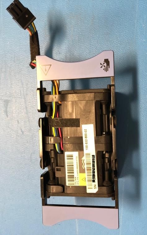
Revisions

Revisions
                 Date                       Description
                 April 2020                 Initial release: PowerStoreOS 1.0

                 September 2020             Minor updates

                 December 2020              PowerStoreOS 1.0.3 updates: Discovery through static IP

                 January 2021               Hardware overview and Metro node updates

                 April 2021                 PowerStoreOS 2.0 updates

                 June 2021                  Minor updates

Acknowledgments
               Author: Ethan Stokes

The information in this publication is provided “as is.” Dell Inc. makes no representations or warranties of any kind with respect to the information in this
publication, and specifically disclaims implied warranties of merchantability or fitness for a particular purpose.

Use, copying, and distribution of any software described in this publication requires an applicable software license.

This document may contain certain words that are not consistent with Dell's current language guidelines. Dell plans to update the document over
subsequent future releases to revise these words accordingly.

This document may contain language from third party content that is not under Dell's control and is not consistent with Dell's current guidelines for Dell's
own content. When such third party content is updated by the relevant third parties, this document will be revised accordingly.

Copyright © 2020–2021 Dell Inc. or its subsidiaries. All Rights Reserved. Dell Technologies, Dell, EMC, Dell EMC and other trademarks are trademarks
of Dell Inc. or its subsidiaries. Other trademarks may be trademarks of their respective owners. [8/9/2021] [Technical White Paper] [H18149.5]

2         Dell EMC PowerStore: Introduction to the Platform | H18149.5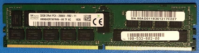
Table of contents

Table of contents
    Revisions.............................................................................................................................................................................2
    Acknowledgments ...............................................................................................................................................................2
    Table of contents ................................................................................................................................................................3
    Executive summary.............................................................................................................................................................5
    Audience .............................................................................................................................................................................5
    1     Introduction ...................................................................................................................................................................6
          1.1      Terminology ........................................................................................................................................................7
    2     PowerStore overview ...................................................................................................................................................9
    3     Hardware overview .....................................................................................................................................................11
          3.1      High availability .................................................................................................................................................12
          3.2      Base enclosure .................................................................................................................................................12
          3.2.1 PowerStore 1000–9000 ....................................................................................................................................13
          3.2.2 PowerStore 500 ................................................................................................................................................18
          3.3      Expansion enclosure ........................................................................................................................................23
          3.4      Drive model comparison ...................................................................................................................................23
          3.4.1 NVMe SSD .......................................................................................................................................................24
          3.4.2 NVMe SCM .......................................................................................................................................................24
          3.4.3 NVMe NVRAM drive .........................................................................................................................................25
          3.4.4 SAS SSD ..........................................................................................................................................................26
          3.5      I/O module ........................................................................................................................................................26
          3.5.1 25 GbE optical (4-port) .....................................................................................................................................26
          3.5.2 32 Gb Fibre Channel (4-port) ...........................................................................................................................27
          3.5.3 10 GbE BASE-T (4-port) ...................................................................................................................................27
    4     PowerStore T models .................................................................................................................................................28
          4.1      Deployment.......................................................................................................................................................28
          4.1.1 Networking and cabling ....................................................................................................................................28
          4.1.2 Discovery ..........................................................................................................................................................31
          4.1.3 Initial configuration ............................................................................................................................................32
          4.2      Deployment modes ...........................................................................................................................................33
          4.2.1 Unified...............................................................................................................................................................33
          4.2.2 Block optimized.................................................................................................................................................34
    5     PowerStore X models .................................................................................................................................................35
          5.1      Deployment.......................................................................................................................................................36
          5.1.1 Networking and cabling ....................................................................................................................................36

3            Dell EMC PowerStore: Introduction to the Platform | H18149.5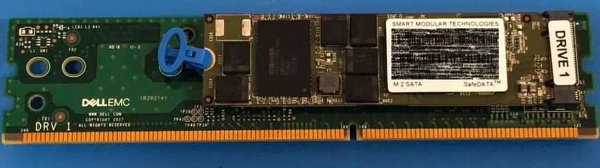
5.1.2 Discovery ..........................................................................................................................................................37
        5.1.3 Initial configuration ............................................................................................................................................39
    6   Conclusion ..................................................................................................................................................................41
    A   Technical support and resources ...............................................................................................................................42

4          Dell EMC PowerStore: Introduction to the Platform | H18149.5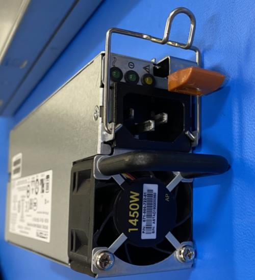
Executive summary

Executive summary
           Dell EMC™ PowerStore™ is designed with two purpose-built platforms. The 2U, two-node dual socket Intel®
           Xeon® platform is used for the PowerStore 1000, 3000, 5000, 7000, and 9000 models. The 2U, two-node
           single-socket Intel® Xeon® platform is used for the PowerStore 500 model. PowerStore provides a data-
           centric, intelligent, and adaptable infrastructure that supports both traditional and modern workloads. This
           white paper details the hardware platform, drives, and various physical components. This document includes
           cabling and deployment guidance for all PowerStore model appliances.

Audience
           This document is intended for IT administrators, storage architects, partners, and Dell Technologies™
           employees. The audience also includes any individuals who may evaluate, acquire, manage, operate, or
           design a Dell EMC networked storage environment using PowerStore systems.

5      Dell EMC PowerStore: Introduction to the Platform | H18149.5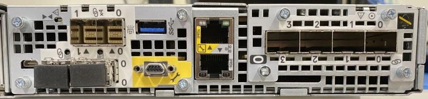
Introduction

1              Introduction
               In this constantly changing world of increasing complexity and scale, the need for an easy-to-use, intelligent
               storage system has only grown greater. Organizations that use new applications and solutions require
               dependable storage and often face the challenge of doing more with less. Dell EMC PowerStore addresses
               this challenge by packaging a powerful storage system into a cost- and space-efficient profile. Some of the
               key PowerStore value propositions listed as follows.

               Active/active architecture: PowerStore uses both nodes to serve host I/O and run data operations in an
               active/active manner. This design efficiently uses all available hardware resources and optimizes
               performance, cost, and density in data centers.

               NVMe platform: PowerStore is designed to use the latest storage and interface technologies to maximize
               application performance and eliminate bottlenecks. PowerStore can maximize performance with NVMe flash
               storage and supports Intel Optane™ storage class memory (SCM) which approaches the speed of DRAM.
               PowerStore supports front-end NVMe connectivity with NVMe over Fibre Channel for a complete end-to-end
               NVMe solution.

               AppsON: Integration of the PowerStore container-based architecture with onboard VMware ESXi™ results in
               a new level of consolidation for enterprise storage. This consolidation provides the benefits of a local, on-
               array application environment and integrates with the VMware® vSphere® management environment and
               server resources. This ability allows users to bring applications closer to storage by running applications as
               virtual machines that run directly on PowerStore. AppsON enables agility for application deployments and
               allows seamless movement between the PowerStore appliances and VMware ESXi™ servers. It also helps
               reduce the server and networking footprint for space-efficient edge and remote deployments. Complemented
               by joint engineering work with VMware and Intel, AppsON uses intellectual property to bypass the hypervisor.
               This ability enables bare-metal NVMe performance with full support for plug-and-play functionality and PCIe
               fault containment.

               VMware integration: PowerStore is designed to have deep integration with VMware vSphere including VAAI,
               VASA, event notifications, snapshot management, VMware vSphere Virtual Volumes™ (vVols), and virtual
               machine discovery and monitoring in PowerStore Manager.

               Unified offering: PowerStore has a single architecture for block, file, and vVols. This architecture uses the
               latest technologies to provide flexible functionality without sacrificing the cost-effective nature of enterprise
               storage. PowerStore provides storage in multiple formats to applications, ranging from physical and virtual
               volumes to containers and traditional files. This ability provides the ultimate workload flexibility and enables IT
               to simplify and consolidate infrastructure.

               A modern, simple interface: PowerStore Manager, the PowerStore management interface, is built with the
               data-center administrator in mind. Using browser-native HTML5, PowerStore Manager can be used across
               various operating systems and web browsers without requiring an external management server or appliance.

               Inline data reduction: Data reduction technologies play a critical role in environments in which storage
               administrators are attempting to do more with less. PowerStore data reduction supports this effort by optimally
               reducing the amount of physical storage that is required to save a dataset. PowerStore data reduction
               provides space savings by using software data deduplication and compression through hardware assist. The
               storage system always enables and intelligently controls data reduction.

               Native data protection: Security and availability of data are critical concerns for many organizations, and
               PowerStore storage offers multiple solutions to address this need. Snapshots provide point-in-time copies of
               block, file, and virtual machine data that can be used for backup and restoration purposes. Asynchronous

6       Dell EMC PowerStore: Introduction to the Platform | H18149.5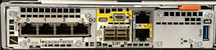
Introduction

               replication offers an IP-based replication strategy within a system or between two systems. Data at Rest
               Encryption (D@RE) ensures that user data on the system is protected from physical theft and can substitute
               drive disposal processes, such as shredding.

1.1            Terminology
               The following terms are used with PowerStore.

               PowerStore Manager: An HTML5 user interface used to manage PowerStore systems.

               PowerStore T model: Container-based storage system that is running on purpose-built hardware. This
               storage system supports unified (block and file) workloads, or block-optimized workloads.

               PowerStore X model: Container-based storage system that runs inside a virtual machine that is deployed on
               a VMware hypervisor. Besides offering block-optimized workloads, PowerStore also allows users to deploy
               applications directly on the array.

               Appliance: Solution containing a base enclosure and any attached expansion enclosures. The size of an
               appliance could be only the base enclosure or the base enclosure plus expansion enclosures.

               Node: Storage controller that provides the processing resources for performing storage operations and
               servicing I/O between storage and hosts. Each PowerStore appliance contains two nodes.

               Cluster: One or more appliances in a single grouping and management interface. Clusters are expandable by
               adding more appliances to the existing cluster, up to the allowed amount for a cluster.

               Base enclosure: Enclosure containing both nodes (node A and node B) and 25 x NVMe drive slots

               Expansion enclosure: Enclosures that can be attached to a base enclosure to provide additional storage.

               Fibre Channel (FC) protocol: Protocol used to perform IP and SCSI commands over a Fibre Channel
               network.

               File system: Storage resource that can be accessed through file-sharing protocols such as SMB or NFS.

               iSCSI: Provides a mechanism for accessing block-level data storage over network connections.

               Volume: A block-level storage device that can be shared out using a protocol such as iSCSI or Fibre
               Channel.

               Network-attached storage (NAS) server: File-level storage server used to host file systems. A NAS server
               is required to create file systems that use SMB or NFS shares.

               Network File System (NFS): An access protocol that allows data access from Linux® or UNIX® hosts on a
               network.

               NVMe over Fibre Channel (NVMe-FC): Allows hosts to access storage systems across a network fabric
               using the NVMe protocol.

               PowerStore Representational State Transfer (REST) API: Set of resources (objects), operations, and
               attributes that provide interactive, scripted, and programmatic management control of the PowerStore cluster.

7       Dell EMC PowerStore: Introduction to the Platform | H18149.5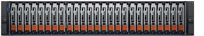
Introduction

               Server Message Block (SMB): An access protocol that allows remote file data access from clients to hosts
               on a network. SMB is typically used in Microsoft® Windows® environments.

               Snapshot: A point-in-time view of data stored on a storage resource. A user can recover files from a
               snapshot, restore a storage resource from a snapshot, or provide access to a host.

               Thin clone: Read-write copy of a volume, volume group, file system, or snapshot that shares blocks with the
               parent resource.

               PowerStore Command Line Interface (PSTCLI): Interface that allows a user to perform tasks on the
               storage system by typing commands instead of using the user interface.

               vSphere API for Array Integration (VAAI): A VMware API that improves ESXi host utilization by offloading
               storage-related tasks to the storage system.

               vSphere API for Storage Awareness (VASA): A VMware vendor-neutral API that enables vSphere to
               determine the capabilities of a storage system. This feature requires a VASA provider on the storage system
               for communication.

               VMware vSphere Virtual Volumes (vVols): A VMware storage framework which allows VM data to be
               stored on individual Virtual Volumes. This ability allows for data services to be applied at a VM-level of
               granularity and according to SPBM. Virtual Volumes can also refer to the individual storage objects that are
               used to enable this functionality.

8       Dell EMC PowerStore: Introduction to the Platform | H18149.5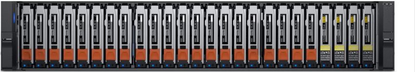
PowerStore overview

2          PowerStore overview
           PowerStore achieves new levels of operational simplicity and agility. It uses a container-based microservices
           architecture, advanced storage technologies, and integrated machine learning to unlock the power of your
           data. A versatile platform with a performance-centric design, PowerStore delivers multidimensional scale,
           always-on data reduction, and support for next-generation media.

           PowerStore brings the simplicity of public cloud to on-premises infrastructure, streamlining operations with an
           integrated machine-learning engine and seamless automation. It offers predictive analytics to easily monitor,
           analyze, and troubleshoot the environment. PowerStore is highly adaptable, providing the flexibility to host
           specialized workloads directly on the appliance and modernize infrastructure without disruption. It also offers
           investment protection through flexible payment solutions and data-in-place upgrades.

           In addition to the traditional consumption option, many PowerStore models make up the underlying storage
           infrastructure for Dell Technologies APEX Data Storage Services. This allows customers to utilize a
           PowerStore solution in an as-a-Service model for ultimate simplicity and agility.

                        PowerStore appliance

           The PowerStore platform is available in two different product model types: PowerStore T and PowerStore X.
           PowerStore T models are bare-metal, unified storage arrays which can service block, file, and vVol resources
           along with numerous data services and efficiencies. PowerStore T models are perfect for traditional and
           modern workloads, with examples including relational databases, electronic medical record applications,
           content repositories, and many more.

           PowerStore X model appliances enable running applications directly on the appliance through the AppsON
           capability. A native VMware ESXi layer runs embedded applications alongside the PowerStore operating
           system, all in the form of virtual machines. This feature is in addition to the traditional storage functionality of
           PowerStore X model appliances, which supports serving external block and vVol storage to servers with FC
           and iSCSI. This innovative design is perfect for storage-heavy applications, providing additional compute and
           high-performance storage to an existing environment, or any scenario where density, performance, and
           availability are primary factors.

           Beyond the power of a single PowerStore model appliance, multiple PowerStore model appliances can be
           grouped into a cluster. A PowerStore cluster can consist of a single-appliance or scale up to four PowerStore

9      Dell EMC PowerStore: Introduction to the Platform | H18149.5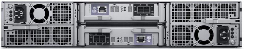
PowerStore overview

           appliances in a single cluster. The cluster enables scaling the compute, storage, and connectivity of the
           PowerStore solution while managing multiple appliances from a single control plane. It can also migrate
           resources between appliances and intelligently load balance new applications based on storage metrics.

           Metro node is an external hardware and software add-on feature for PowerStore, and it provides active/active
           synchronous replication plus standard local use cases. It also provides a solution locally with the local mirror
           feature to protect data from a potential array failure. Both use cases provide solutions for true continuous
           availability with zero downtime.

           PowerStore is viewed by metro node as an Asymmetric Logical Unit Access (ALUA) array based on SCSI
           response data, and is required to follow the four-active, four-passive path connectivity rules. This rule states
           that both nodes of the metro node must each have four active and four passive paths to all volumes
           provisioned from the array. For more information about Metro node, see the document Dell EMC PowerStore
           Metro Node.

10     Dell EMC PowerStore: Introduction to the Platform | H18149.5
Hardware overview
3 Hardware overview
The purpose-built PowerStore system is offered in multiple physical hardware models in both PowerStore T
and PowerStore X appliances. The PowerStore T model series starts with the PowerStore 500T and scales
up to the PowerStore 9000T. The PowerStore X model series starts with the PowerStore 1000X and scales
up to the PowerStore 9000X. A letter T or X may be listed at the end of the model number, indicating whether
the specific appliance is a PowerStore T or PowerStore X model, respectively. For each model numeral, such
as 1000 (for PowerStore 1000T or 1000X models), the hardware specifications are identical. The two different
PowerStore options are often grouped when hardware is referenced, and the T or X is omitted from the model
number. See Table 1 for model comparisons.
The PowerStore 500 is a new PowerStore model introduced in the PowerStoreOS 2.0 release. This model
runs on a dual-node, single-socket Intel® Xeon® platform and runs the PowerStoreOS 2.0 software. The
PowerStore 500 runs the same PowerStoreOS as all other PowerStore T models. PowerStoreOS 1.0 and all
PowerStoreOS 1.0 service packs are not supported on the PowerStore 500 appliance.
The system limits vary depending on the PowerStore model. You can learn more about the system limits on
the PowerStore Info Hub.
PowerStore model comparison
PowerStore PowerStore PowerStore PowerStore PowerStore PowerStore
500 1000 3000 5000 7000 9000
NVRAM 0 2 4
drives
Maximum 25 96
storage
drives (per
appliance)
Supported NVMe SCM, NVMe SCM, NVMe SSD, SAS SSD1
drive types NVMe SSD
4-port card 25/10/1 GbE 25/10/1 GbE optical/SFP+ and Twinax
optical/SFP+ or
and Twinax2 10/1 GbE BASE-T
2-port card 10 GbE -
optical/SFP+
and Twinax
Supported 32/16/8 Gb FC or 16/8/4 Gb FC
I/O modules
(2 per node) 25/10/1 GbE optical/SFP+ and Twinax (PowerStore T only)
10/1 GbE BASE-T (PowerStore T only)
Supported None 2.5-inch 25-drive SAS SSD
expansion
enclosures
1
SAS SSDs only supported in expansion enclosure.
2
Ports 2 and 3 on the 4-Port Mezzanine card on PowerStore 500 are reserved for future use
11 Dell EMC PowerStore: Introduction to the Platform | H18149.5Hardware overview
3.1 High availability
PowerStore features fully redundant hardware and includes several high availability features. These features
are designed to withstand component failures within the system itself and environmental failures such as
network or power outages. If an individual component fails, the storage system remains online and continues
to serve data. The system can also withstand multiple failures if they occur in separate component sets. After
the administrator is alerted about the failure, they can order and replace the failed component without impact.
PowerStore is a dual-node architecture which includes two identical nodes for redundancy. It features an
active/active controller configuration where both nodes are servicing I/O simultaneously. This increases
hardware efficiency, since there are no requirements for idle standby hardware. These nodes, along with up
to twenty-five 2.5-inch drives, are enclosed within the base enclosure, all in a 2U form factor.
The following sections cover the different hardware components of the PowerStore platform. Specific sections
detail the redundancy and high availability features of that component and how it pertains to PowerStore. For
more information about high availability at the software and cluster level, see the document Dell EMC
PowerStore: Clustering and High Availability.
3.2 Base enclosure
The PowerStore base enclosure supports 25 all-NVMe 2.5-inch drives in a 2U chassis. The base enclosure is
secured into a rack using toolless snap-in rails. The rails ship with every system and allow for easy installation
of a PowerStore system. The base enclosure securely latches onto the snap-in rails when fully inserted into
the rack. If you must remove the enclosure from the rails, lift a bottom latch on each side of the base
enclosure to pull the base enclosure out. While the base enclosure securely latches onto the rails, there are
optional screws underneath each latch which you can tighten for additional security.
The front of the base enclosure contains an LED to display different states of the system. This LED is in the
upper-left side of the chassis near drive slot 0. The LED states and corresponding system status are shown in
Table 2. Each of the 2.5-inch drives contain both a drive power and activity LED, and a drive fault LED. The
drive fault LED illuminates amber when a drive becomes faulted. There is also an option in PowerStore
Manager to blink a specific drive to identify it using the fault LED. If the drive-power and activity LED is
powered on and active, it blinks blue.
12 Dell EMC PowerStore: Introduction to the Platform | H18149.5Hardware overview
Base enclosure LED status description
LED state System status
Blue Power is on. No fault has occurred.
Amber Power is on. Fault has occurred within the enclosure.
Blue and amber alternating Power is on. System is not initialized.
Off Power is off.
The data storage drives are populated from left to right, starting in slot 0. PowerStore requires a minimum of
six storage drives. User data, metadata, and system data are automatically stored and protected across the
available storage drives using the PowerStore Dynamic Resiliency Engine (DRE). For more information about
PowerStore DRE, see the document Dell EMC PowerStore: Clustering and High Availability.
3.2.1 PowerStore 1000–9000
The base enclosure for PowerStore 1000, PowerStore 3000, PowerStore 5000, PowerStore 7000, and
PowerStore 9000 models supports twenty-five all-NVMe 2.5-inch drives in a 2U chassis. Figure 2 shows the
base enclosure for a PowerStore system with 21 NVMe SSDs and four NVMe NVRAM drives.
Base enclosure front view
The back of the base enclosure reveals the nodes and their connectivity options (Figure 3). Each node has
one embedded module and two I/O module slots (optional) for network connectivity. Each node has a
dedicated 1 GbE BASE-T service port which can be used for on-site support access and initial configuration
of the system. Each node also contains a second 1 GbE BASE-T port. This port is used for management
traffic in PowerStore T model appliances and is unused in PowerStore X model appliances. These embedded
1 GbE BASE-T ports are both contained on the embedded module of the node.
For more information about the base enclosure and base enclosure components, see the Dell EMC
PowerStore Hardware Information Guide.
Base enclosure back view
13 Dell EMC PowerStore: Introduction to the Platform | H18149.5Hardware overview
3.2.1.1 Drives
The base enclosure is an all-NVMe platform, capable of supporting NVMe SSD, NVMe SCM, and NVMe
NVRAM drives. You can populate slots 0 through 20 with NVMe SSD or NVMe SCM drives. Slots 21 through
24 are reserved for NVMe NVRAM drives which serve as additional system write caching. PowerStore 1000
and PowerStore 3000 models contain two NVMe NVRAM drives in slots 23 and 24. PowerStore 5000,
PowerStore 7000, and PowerStore 9000 models contain four NVMe NVRAM drives in slots 21 through 24. In
models that only use two NVMe NVRAM drives, slots 21 and 22 are not available for storage drives.
Systems running PowerStoreOS 1.0 cannot mix NVMe SSD and NVMe SCM drives in the same base
enclosure. PowerStore systems require a minimum of six NVMe SSD or six NVMe SCM drives, which can be
scaled up in single-drive increments.
Starting with PowerStoreOS 2.0, systems can support one or more NVMe SCM drives mixed with NVMe SSD
drives for metadata tiering. NVMe SCM drives provide lower latency than NVMe SSD drives and can improve
system performance by storing metadata on these low-latency drives. On a system which contains both
NVMe SCM and NVMe SSD, the NVMe SCM drives are dedicated to metadata and all user data is stored on
NVMe SSD drives. PowerStore requires a minimum of six NVMe SSD drives for systems containing entirely
NVMe SSD, or systems containing NVMe SSD supplemented with NVMe SCM. PowerStore requires a
minimum of six NVMe SCM drives for system containing entirely NVMe SCM.
The expansion enclosures support SAS drives for expansion capacity beyond the all-NVMe base enclosure.
Expansion enclosures are not supported on systems containing entirely NVMe SCM drives. Systems running
PowerStoreOS 2.0 and containing a mix of NVMe SSD and NVMe SCM drives do support adding an
expansion enclosure. For more details about PowerStore drives, see section 3.4.
3.2.1.2 Node
The purpose-built PowerStore platform is powered by dual-socket Intel® Xeon® processors. Each purpose-
built PowerStore system contains two nodes, which are used for high-availability and load-balancing
purposes.
Each node is 1U in size and stacks vertically in the base enclosure, with the top node inverted. The bottom
PowerStore node is node A, and the top PowerStore node is node B. Each node can access each drive
through the midplane connection inside the base enclosure. Each node contains the following components,
which are detailed in the following sections.
• Internal M.2 boot module
• Fan modules
• Battery backup unit
• DIMMs
• Embedded module
• I/O module
• Power supply
14 Dell EMC PowerStore: Introduction to the Platform | H18149.5Hardware overview
3.2.1.3 Internal M.2 boot module
Each node has a primary and a secondary M.2 SATA device inside the system on a riser card between DIMM
slots 11 and 12 (see Figure 4). The primary M.2 device is 240 GB and the primary boot device for the node.
PowerStore uses this device to store the base operating system, log files, and for general system operations.
The secondary M.2 device is 120 GB. PowerStore uses this device for recovery during a primary M.2 failure,
and it is an alternate location for log files.
Internal M.2 boot module
3.2.1.4 Fan modules
PowerStore uses fan modules (cooling modules) to provide cool airflow to the node interior to ensure that the
internal components remain at optimal operating temperatures (see Figure 5). Each node contains seven
redundant fan modules that are connected to the motherboard within the node. A node can tolerate a single
fan module fault, and the surviving fans increase their speed to compensate for the faulted module. If two fan
modules fault within the same node, the node performs a protective thermal shutdown. A protective thermal
shutdown gracefully powers off the node, and any resource fails over to the surviving node.
Fan module
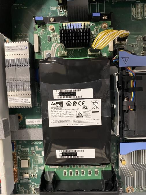
3.2.1.5 Battery backup unit
If system power is lost, the battery backup unit (BBU) provides power to the NVRAM drive slots and the
baseboard management controller (BMC). This action allows the NVRAM drive drives to vault their volatile
data to nonvolatile storage within the same drive and persist the information. Once the NVRAM drives have
completed their vault, the BMC powers off the system. The BBU in node A provides power for drive slots 21
and 23. The BBU in node B provides power for drive slots 22 and 24. The NVRAM drives are in mirrored sets
consisting of drives in slots 23 and 24. If the PowerStore model supports four NVRAM drives, there is another
mirrored set in slots 21 and 22. The node BBUs are configured so that both BBUs power each NVRAM
15 Dell EMC PowerStore: Introduction to the Platform | H18149.5Hardware overview
mirrored pair, ensuring that there is no single point of failure. Each BBU contains sufficient charge to
accommodate multiple back-to-back power failures. Once power is resumed, the BBUs gradually recharge.
Battery backup unit
3.2.1.6 DIMMs
Each node contains 24 DDR4 DIMM slots, which are populated in different configurations that are based on
the PowerStore model. All host data is written to the NVMe NVRAM drive from DRAM before the host is
acknowledged to protect against data loss upon system power failure.
DIMM
3.2.1.7 Embedded module
Each node contains a single embedded module which has different connectivity components. The embedded
module supports network connectivity for data storage, management and service access, cluster
communication, and SAS connectivity to expansion enclosures. The embedded module contains the following
components:
• 4-port card
• Non-maskable interrupt (NMI) button
• Mini-SAS HD back-end ports
• System management port (1 GbE) (used with PowerStore T models only)
• Service port (1 GbE)
• USB port
There are two 4-port card options that are supported in the embedded module:
• 10/1 GbE BASE-T (4-port)
• 25/10/1 GbE optical/SFP+ and Twinax (4-port)
The 4-port card (Figure 8) selected for the embedded module on node A must be the same 4-port card in the
embedded module on node B. You can select the 4-port card configuration at the time of ordering but cannot
change the configuration later. You must configure ports 0 and 1 with a link speed of at least 10 GbE on the
4-port card. This configuration ensures that intercluster traffic, which uses ports 0 and 1, has sufficient
16 Dell EMC PowerStore: Introduction to the Platform | H18149.5Hardware overview
bandwidth. Ports 2 and 3 support all advertised speeds (10/1 GbE BASE-T or 25/10/1 GbE optical/SFP+ and
Twinax).
Embedded module with 10/1 GbE BASE-T 4-port card
3.2.1.8 I/O module
Each node on PowerStore systems can support up to two I/O modules that provide extra connectivity. For the
two nodes in a base enclosure, the I/O modules that are configured must match between nodes. During a
node failure, matching I/O modules ensure that the peer node can begin servicing I/O using the mirrored I/O
module.
PowerStore systems support the following I/O modules:
• 25/10/1 GbE optical/SFP+ and Twinax (4-port)
• 32/16/8/4 Gb Fibre Channel (4-port)
• 10/1 GbE BASE-T (4-port)
For more details about I/O modules, see section 3.5.
3.2.1.9 Power supply
The PowerStore platform contains two power supply units (PSUs) in the base enclosure and offers PSUs with
two wattage options that are based on the model. PowerStore 1000T/X, PowerStore 3000T/X, and
PowerStore 5000T models support both the 1800 W high-line and 2100 W high-line PSUs. For environments
which only provide low-line power, you can use the 2100 W PSU with a step-up transformer. Do not select the
1800 W PSU for environments with low-line power. PowerStore 5000X, PowerStore 7000T/X, and
PowerStore 9000T/X models support only the 2100 W PSU. For environments which only offer low-line
power, you can use the 2100 W PSU with a step-up transformer. Table 3 shows the PSU specifications per
PowerStore model.
Power supplies
Model Power supply wattage Connector support
PowerStore 1000T/X, 3000T/X, 5000T 1800 W1 or 2100 W2 1800 W: C13/14 or
C13/20
2100 W: C19/C20
PowerStore 5000X, 7000T/X, 9000T/X 2100 W2 2100 W: C19/20
1
Supports high-line power only
2
Supports high-line power and low-line power with step-up transformer
Figure 9 shows the supported connector types.
17 Dell EMC PowerStore: Introduction to the Platform | H18149.5Hardware overview
C19/C20, C13/C20, and C13/C14 connectors
A single power supply (Figure 10) can power the entire base enclosure during a power supply failure. Power
supplies can be replaced without having to remove the node. Power supplies are offered for AC power only.
2100 W power supply
3.2.2 PowerStore 500
The PowerStore 500 base enclosure supports 25 all-NVMe 2.5-inch drives in a 2U chassis. The PowerStore
500 is introduced in the PowerStoreOS 2.0 release and requires PowerStoreOS 2.0 as a minimum supported
software version.
The back of the base enclosure shows the nodes and their connectivity options. Each node has one
embedded module and two I/O module slots (optional) for network connectivity. Each node has a dedicated 1
GbE BASE-T service port which can be used for on-site support access and initial configuration of the
system. Each node also contains a second 1 GbE BASE-T port which is used for management traffic. The
embedded module of the node contains both of these embedded 1 GbE BASE-T ports.
For more information about the base enclosure and base enclosure components, see the Dell EMC
PowerStore Hardware Information Guide for PowerStore 500 Models on the PowerStore Info Hub.
3.2.2.1 Drives
The base enclosure is an all-NVMe platform, capable of supporting NVMe SSD and NVMe SCM drives. You
can populate slots 0 through 24 with NVMe SSD or NVMe SCM drives. PowerStore 500 systems use internal
DRAM for write caching and do not support NVMe NVRAM drives.
PowerStore 500 systems can support one or more NVMe SCM drives mixed with NVMe SSD drives for
metadata tiering. NVMe SCM drives provide lower latency than NVMe SSD drives and can improve system
performance by storing metadata on these low-latency drives. On a system which contains both NVMe SCM
18 Dell EMC PowerStore: Introduction to the Platform | H18149.5Hardware overview
and NVMe SSDs, the NVMe SCM drives are dedicated to metadata, and all user data is stored on NVMe
SSD drives. PowerStore requires a minimum of six NVMe SSD drives for systems containing entirely NVMe
SSD, or systems containing NVMe SSD supplemented with NVMe SCM. PowerStore requires a minimum of
six NVMe SCM drives for system containing entirely NVMe SCM.
PowerStore 500 systems do not support expansion enclosures. For more details about PowerStore drives,
see section 3.4.
3.2.2.2 Node
The purpose-built PowerStore 500 platform is powered by a single-socket Intel® Xeon® Processor. Each
purpose-built PowerStore 500 system contains two nodes, which are used for high-availability and load-
balancing purposes.
Each node is 1U and stacks vertically in the base enclosure, with the top node inverted. The bottom
PowerStore node is node A, and the top PowerStore node is node B. Each node can access each drive
through the midplane connection inside the base enclosure. Each node contains the following components,
which are detailed in the following sections.
• Internal M.2 boot module
• Fan modules
• Battery backup unit
• DIMMs
• Embedded module
• I/O module
• Power supply
3.2.2.3 Internal M.2 boot module
A single M.2 SATA device is located inside each node across from the CPU and DIMM complex. The M.2
device is 240 GB and is the primary boot device for the node. It stores the base operating system, log files,
and vaulted cache data, and is used for general system operations.
Internal M.2 boot module
3.2.2.4 Fan modules
Fan modules (cooling modules) provide cool airflow to the node interior to ensure that the internal
components remain at optimal operating temperatures (see Figure 12). Each node contains six redundant fan
modules that are connected to the motherboard within the node. A node can tolerate a single fan module
fault, and the surviving fans increase their speed to compensate for the faulted module. If two fan modules
fault within the same node, the node performs a protective thermal shutdown. A protective thermal shutdown
gracefully powers off the node, and any resource fails over to the surviving node.
19 Dell EMC PowerStore: Introduction to the Platform | H18149.5Hardware overview
Fan module
3.2.2.5 Battery backup unit
If the system loses power, the battery backup unit (BBU) provides power to the node to enable cache
vaulting. This feature allows the node to encrypt and back up dirty cache data during power loss from the
system DRAM to the internal M.2 boot module. This BBU and vaulting process replaces the BBU and NVRAM
self-vaulting process of the PowerStore 1000 to PowerStore 9000 models. After each node completes the
vault of cached data, the node powers off. Each BBU contains sufficient charge to accommodate multiple
back-to-back power failures. After power is resumed, the BBUs gradually recharge. The BBU is located
between the third and fourth fan, in the middle of the enclosure.
Battery backup unit
3.2.2.6 DIMMs
Each PowerStore 500 node is configured with DDR4 DIMMs. To protect against data loss, all host data is
mirrored to the peer node before the host is acknowledged. Each node is equipped with a BBU to vault
cached data to the internal M.2 boot module upon system power failure. For more detail on the PowerStore
500 write caching architecture, see the document the PowerStore: Data Efficiencies.
20 Dell EMC PowerStore: Introduction to the Platform | H18149.5Hardware overview
DIMM
3.2.2.7 Embedded module
Each node contains a single embedded module which has different connectivity components. The embedded
module supports network connectivity for data storage, management and service access, and cluster
communication. The embedded module contains the following components:
• 25/10/1 GbE optical/SFP+ and Twinax 4-port card (optional)
• 10 GbE optical/SFP+ and TwinAx 2-port card
• Mini-SAS HD back-end ports
• System management port (1 GbE)
• Service port (1 GbE)
The 4-port card is optional, and you can select it at the time of ordering. The 4-port card is required to support
unified deployment mode (file services) and clustering with other appliances. If you do not select a 4-port
card, you can deploy the system only in block-optimized mode. For more information about the deployment
modes, see section 4.2.
If you configure the 4-port card for the embedded module on node A, you must also configure a 4-port card on
node B. You cannot add or remove the 4-port card after you complete the initial configuration. If you select a
4-port card, you must configure ports 0 and 1 with a link speed of at least 10 GbE on the 4-port card. This
configuration ensures that intercluster traffic which uses ports 0 and 1 has sufficient bandwidth. Ports 2 and 3
are not supported for customer use and are reserved for future PowerStoreOS releases.
You can use the embedded 2-port card for front-end iSCSI connectivity and replication. This 2-port card is a
fixed 10 GbE card which comes standard on all PowerStore 500 systems. The 2-port card supports SFPs and
passive TwinAx running at 10 GbE speeds.
Embedded module with 4-port card
3.2.2.8 I/O module
Each node on PowerStore 500 systems can support up to two I/O modules that provide extra connectivity.
For the two nodes in a base enclosure, the I/O modules that are configured must match between nodes.
During a node failure, matching I/O modules ensure that the peer node can begin servicing I/O using the
mirrored I/O module.
PowerStore 500 systems support the following I/O modules:
21 Dell EMC PowerStore: Introduction to the Platform | H18149.5Hardware overview
• 25/10/1 GbE optical/SFP+ and Twinax (4-port)
• 32/16/8/4 Gb Fibre Channel (4-port)
• 10/1 GbE BASE-T (4-port)
For more details about I/O modules, see section 3.5.
3.2.2.9 Power supply
The PowerStore 500 platform contains two power supply units (PSUs) in the base enclosure and comes with
a PSU which supports 1450 W high-line and low-line power. The PowerStore 500 PSU supports C13/C20 or
C13/C14 connectors. Figure 16 shows the supported connector types.
C13/C20 and C13/C14 connectors
A single power supply (Figure 17) can power the entire base enclosure during a power-supply failure. You
can replace the power supplies without removing the node. Power supplies are offered for AC power only.
1450 W power supply
22 Dell EMC PowerStore: Introduction to the Platform | H18149.5Hardware overview
3.3 Expansion enclosure
The purpose-built PowerStore 1000 to PowerStore 9000 systems support a 25-drive 2U expansion enclosure
(Figure 18) using 2.5-inch SAS drives for extra capacity. Expansion enclosures are not supported with
PowerStore systems using only NVMe SCM drives or PowerStore 500 systems. These expansion-enclosure
restrictions only apply to the specific base enclosure of the appliance that the expansion enclosure is being
added to. Expansion enclosure restrictions on an appliance do not impact other systems within a multi-
appliance PowerStore cluster.
25-drive 2.5-inch 2U expansion enclosure (front)
The back of the expansion enclosure (Figure 19) includes LEDs to indicate power and fault status. There are
also LEDs to indicate bus and enclosure IDs.
25-drive 2.5-inch 2U expansion enclosure (back)
3.4 Drive model comparison
PowerStore supports multiple drive types and capacity points. The base enclosure is an all-NVMe platform,
capable of supporting NVMe SSD, NVMe SCM, and NVMe NVRAM drives. The expansion enclosures
support SAS drives for expansion capacity beyond the all-NVMe base enclosure. You can add expansion
enclosures only to systems which have fully occupied all 21 slots that support NVMe SSDs in the base
enclosure. Expansion enclosures are not supported on systems with only NVMe SCM drives in the base
enclosure. A list of all supported drives is available on Dell Support.
SAS SSD, NVMe SSD, and NVMe SCM are considered to be storage drives in PowerStore and are formatted
with a 512-byte block size. You can populate slots 0 through 20 on PowerStore 1000 to 9000 models and
slots 0 through 24 on the PowerStore 500 model with only NVMe SSD or NVMe SCM drives. Starting in
PowerStoreOS 2.0, you can mix NVMe SSD and NVMe SCM drives in the same enclosure. Earlier releases
of PowerStoreOS do not support mixing these drives. PowerStore systems require a minimum of six NVMe
SSD or six NVMe SCM drives, which can be scaled up in single-drive increments. Slots 21 through 24 in
PowerStore 1000 to 9000 models are reserved for NVMe NVRAM drives which serve as extra system write
caching. Based on the PowerStore model, there are either two NVMe NVRAM drives in slots 23 and 24, or
four NVMe NVRAM drives in slots 21 through 24. In models that only use two NVMe NVRAM drives, slots 21
and 22 are not available for storage drives.
23 Dell EMC PowerStore: Introduction to the Platform | H18149.5Hardware overview
3.4.1 NVMe SSD
NVMe solid-state drives (SSDs) are dual-ported, high-performance, nonvolatile flash drives that the
PowerStore operating system accesses with NVMe. NVMe is a protocol that allows access directly with the
PCIe bus. NVMe is designed to capitalize on the low latency of high-performance media.
NVMe SSDs serve as the storage tier for PowerStore, are used for user data or metadata, and come in
multiple capacity points. See Table 4 for a complete list of capacity points and supported platforms.
NVMe SSD drive size and support
Storage type Usage GB PowerStore 1000–9000 PowerStore 500
NVMe SSD User data/ 1,920 ✓ ✓
metadata
3,840 ✓ ✓
7,680 ✓ ✓
15,360 ✓ ✓
NVMe SSDs are supported in base enclosure slots 0 through 20 on PowerStore 1000 to PowerStore 9000
models and in base enclosure slots 0 through 24 on PowerStore 500 models. Starting with PowerStoreOS
2.0, you can mix NVMe SSDs with NVMe SCM drives. PowerStoreOS 1.0 and associated service packs do
not support mixing NVMe SSD and NVMe SCM drives.
3.4.2 NVMe SCM
NVMe storage class media (SCM) drives are dual-ported, extreme-high-performance, nonvolatile drives that
are designed with Intel Optane™ technology. NVMe SCM drives have lower latency and improved
performance compared to other SSD drives, and the PowerStore operating system accesses them with
NVMe. NVMe is a protocol that allows access directly with the PCIe bus. NVMe is designed to capitalize on
the low latency of high-performance media.
NVMe SCM drives serve as a storage tier for PowerStore, are used for user data or metadata, and come in
three capacity points. See Table 5 for a complete list of capacity points and supported platforms.
NVMe SCM drive size and support
Storage type Usage GB PowerStore 1000–9000 PowerStore 500
NVMe SCM User data/ 375 ✓ ✓
metadata
750 ✓ ✓
1500 ✓ -
NVMe SCM drives are supported in base enclosure slots 0 through 20 on PowerStore 1000 to PowerStore
9000 models and in base enclosure slots 0 through 24 on PowerStore 500 models. Starting with
PowerStoreOS 2.0, you can mix NVMe SCMs with NVMe SSD drives. NVMe SCM drives serve as a
dedicated metadata tier when mixed with NVMe SSD drives. PowerStoreOS 1.0 and associated service
packs do not support mixing NVMe SCM and NVMe SSD drives. A PowerStore system with only NVMe SCM
storage drives does not support any expansion enclosures.
24 Dell EMC PowerStore: Introduction to the Platform | H18149.5Hardware overview
3.4.3 NVMe NVRAM drive
NVMe NVRAM drives are dual-ported, extreme-high-performance drives used to enhance the PowerStore
caching system. The dual-ported drives are accessible from both nodes and allow the system to easily cache
incoming writes. The drives contain dynamic media which can operate at DRAM speeds over PCIe, delivering
exceptional performance. Their design allows them to function as nonvolatile media, and PowerStore can
quickly store incoming writes and acknowledge the host without mirroring data to the peer node. The drives
contain a combination of persistent flash storage within the 2.5-inch NVMe NVRAM paddle card and access
to a battery. During a power failure, these features allow the drive to vault the data from the high-performance
dynamic media to the persistent flash storage. The NVMe NVRAM drives are 8 GB and are configured in
mirrored sets. These drives are supported on PowerStore 1000 to PowerStore 9000 models, and there are
two or four drives per appliance, depending on the model (see Table 6).
NVMe NVRAM count by PowerStore model
NVMe NVRAM
PowerStore model
count
PowerStore 500 0
PowerStore 1000 2
PowerStore 3000
PowerStore 5000 4
PowerStore 7000
PowerStore 9000
The battery backups are wired so that each mirrored set of drives has access to two separate battery
backups. This configuration ensures that a faulty battery backup could not result in a failed data vault for an
entire mirrored pair. The number of NVMe NVRAM drives are fixed per model, and you cannot modify them.
You may not add extra NVMe NVRAM drives later.
For more information about the role of NVMe NVRAM drives in the PowerStore write path, see the document
Dell EMC PowerStore: Data Efficiencies.
25 Dell EMC PowerStore: Introduction to the Platform | H18149.5Hardware overview
3.4.4 SAS SSD
SAS SSDs are dual-ported, high-performance, nonvolatile flash drives that the PowerStore operating system
accesses through the SAS protocol. SAS SSDs are only supported in expansion enclosures and are not
supported with PowerStore 500 models.
SAS SSDs supplement the storage tier for PowerStore, are used for user data or metadata, and are available
in multiple capacity points. See Table 7 for a complete list of capacity points and supported platforms.
SAS SSD drive size and support
Storage type Usage GB PowerStore 1000–9000 PowerStore 500
SAS SSD User data/ 1,920 ✓ -
metadata
3,840 ✓ -
7,680 ✓ -
3.5 I/O module
Each node on PowerStore systems can support up to two I/O modules that provide extra connectivity. For the
two nodes in a base enclosure, the I/O modules that are configured must match between nodes. During a
node failure, matching I/O modules ensure that the peer node can begin servicing I/O using the mirrored I/O
module.
PowerStore systems support the following I/O modules:
• 25/10/1 GbE optical/SFP+ and Twinax (4-port) (PowerStore T models only)
• 32/16/8/4 Gb Fibre Channel (4-port)
• 10/1 GbE BASE-T (4-port) (PowerStore T models only)
3.5.1 25 GbE optical (4-port)
The 25 GbE optical I/O module (Figure 20) supports SFPs running at 25 GbE, 10 GbE, or 1 GbE speeds. The
optical I/O module ports also support 10 GbE active and passive Twinax, and 25 GbE passive Twinax
connections. You can mix different SFPs or Twinax cables on the same I/O module, and they are hot-
swappable. This I/O module supports iSCSI traffic.
25 GbE optical I/O module
26 Dell EMC PowerStore: Introduction to the Platform | H18149.5Hardware overview
3.5.2 32 Gb Fibre Channel (4-port)
The 32 Gb Fibre Channel (4-port) I/O module (Figure 21) supports 32 Gb/s and 16 Gb/s SFPs. The 32 Gb/s
SFP offers front-end connectivity at 32 Gb/s speeds and can autonegotiate to 16 Gb/s and 8 Gb/s. The 16
Gb/s SFP offers front-end connectivity at 16 Gb/s and can autonegotiate to 8 Gb/s and 4 Gb/s.
Starting with PowerStoreOS 2.0, PowerStore systems with the 32 Gb Fibre Channel I/O module support
NVMe over Fibre Channel. NVMe over Fibre Channel support with PowerStore requires 32 Gb speeds, and
the Fibre Channel I/O module must be configured with 32 Gb SFPs to support this feature.
32 Gb Fibre Channel I/O module
3.5.3 10 GbE BASE-T (4-port)
The 10 GbE BASE-T (4-port) I/O module (Figure 22) operates at up to 10 Gb/s speeds. It is used for front-end
host access and supports both iSCSI and NAS protocols. The I/O module can also autonegotiate to 1 Gb/s
speeds as needed.
10 GbE BASE-T I/O module
27 Dell EMC PowerStore: Introduction to the Platform | H18149.5PowerStore T models
4 PowerStore T models
PowerStore T model appliances include one of two model types within the PowerStore platform. This
distinction is denoted by the letter T which follows a given model number, such as PowerStore 9000T.
PowerStore T models have the purpose-built PowerStore platform that is detailed in section 3. Built with a
microservices and container-based architecture, the PowerStore operating system is designed to take full
advantage of the cutting-edge technology of the underlying platform.
PowerStore T models are unified storage arrays. They can serve block storage (with iSCSI, Fibre Channel, or
NVMe over Fibre Channel), file storage (with SMB, NFS, FTP, SFTP), and vVol storage (with iSCSI or Fibre
Channel). The workflows and operations between block, file, and vVol storage are built on the same engine,
and users can control all aspects of the array. The PowerStore single architecture that supports block, file,
and vVols allows the platform to accommodate a wide variety of traditional and modern workloads. By
providing storage in multiple formats to applications, PowerStore delivers workload flexibility and enables
administrators to simplify and consolidate infrastructure.
4.1 Deployment
After you rack the system, a single PowerStore T model appliance requires simple network cabling to the
physical Ethernet and management switches. Complete the cabling, and then apply the proper switch
configuration to support management and data traffic from the appliance. Finally, connect the power cables
and power on the appliance. After the PowerStore system is online, launch the Initial Configuration Wizard
and configure the system.
The Initial Configuration Wizard is an HTML5-based configuration wizard that is hosted on the appliance.
PowerStore X model appliances also use the same wizard with slight modifications. The Initial Configuration
Wizard gathers all necessary information about networking and infrastructure services. The appliance
automatically applies this configuration and brings PowerStore into a configured, operational state.
For details about configuring a multi-appliance PowerStore T cluster, adding a PowerStore T model appliance
to an existing cluster, or removing an appliance, see the document Dell EMC PowerStore: Clustering and
High Availability.
For details about PowerStore deployment and configuration in general, see the Dell EMC PowerStore: Quick
Start Guide. This document contains an overview of PowerStore deployment and directs readers to all
necessary documentation and resources for a successful installation.
4.1.1 Networking and cabling
PowerStore T model appliances require two physical Ethernet switches with Layer 2 connectivity and at least
one management switch. The Ethernet switches ensure high availability for iSCSI, NAS, replication, external
storage import, data migration, and intercluster traffic. Properly configuring and cabling to the physical
Ethernet switches ensures that all capabilities of PowerStore are ready for use when the Initial Configuration
is complete.
28 Dell EMC PowerStore: Introduction to the Platform | H18149.5You can also read