Dell Precision 7920 Rack - A6000 graphic card Installation Guide
←
→
Page content transcription
If your browser does not render page correctly, please read the page content below
Dell Precision 7920 Rack
A6000 graphic card Installation Guide

Regulatory Model: E38S
Regulatory Type: E38S001
September 2021
Rev. A00
Notes, cautions, and warnings

     NOTE: A NOTE indicates important information that helps you make better use of your product.

     CAUTION: A CAUTION indicates either potential damage to hardware or loss of data and tells you how to avoid
     the problem.

     WARNING: A WARNING indicates a potential for property damage, personal injury, or death.

© 2021 Dell Inc. or its subsidiaries. All rights reserved. Dell, EMC, and other trademarks are trademarks of Dell Inc. or its subsidiaries. Other
trademarks may be trademarks of their respective owners.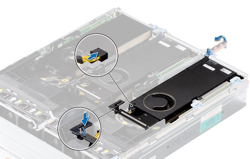
Contents

Chapter 1: Introduction................................................................................................................. 4
  Product overview................................................................................................................................................................ 4
  Operating system.................................................................................................................................................................4

Chapter 2: Field service information..............................................................................................5
  Safety instructions.............................................................................................................................................................. 5
     Safety precautions........................................................................................................................................................ 5
     Electrostatic discharge—ESD protection............................................................................................................... 6
     ESD field service kit ..................................................................................................................................................... 6
     Transporting sensitive components.......................................................................................................................... 7
     Recommended tools......................................................................................................................................................8
     Disassembly and reassembly....................................................................................................................................... 8

Chapter 3: Getting help and contacting Dell.................................................................................15

                                                                                                                                                        Contents                   3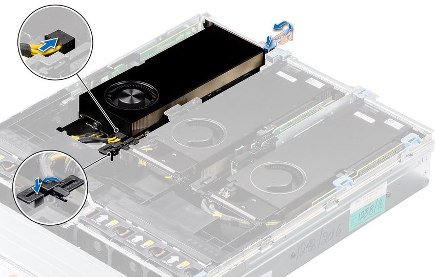
1
                                                                                             Introduction
Product overview
Dell Precision 7920 Rack is a refresh to Dell Precision Rack 7910 2U Rack featuring the Intel EP Skylake processor update
(PurleyPlatform). Supports incremental updates to graphics, manageability updates, security updates, other Dell end-user
solutions, and client operating system options.

Key features
●   8xPCIe slots
●   Supports 8x3.5 SATA/SAS drive (2.5 with adapters)
●   Maximum memory is 768 GB per processor.
●   Support Intel Xeon EP Processor including Top Bins.
●   Huge Performance increases with tuning for leading ISV workloads.

Operating system
Your Precision 7920 Rack supports the following operating systems:
●   Windows   11 Pro, 64-bit
●   Windows   11 Pro for Workstations, 64-bit
●   Windows   10 Pro, 64-bit
●   Windows   7 Pro, 32-bit (downgradable)
●   Windows   7 Pro, 64-bit (downgradable)

4       Introduction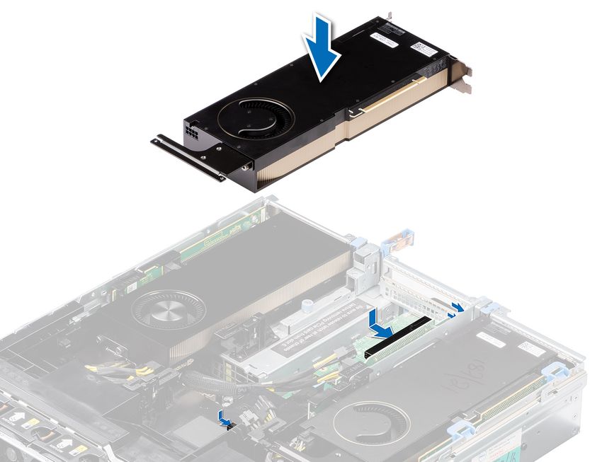
2
                                                          Field service information
Safety instructions
Use the following safety guidelines to protect your computer from potential damage and to ensure your personal safety. Unless
otherwise noted, each procedure included in this document assumes that you have read the safety information that shipped
with your computer.
    WARNING: Before working inside your computer, read the safety information that is shipped with your
    computer. For more safety best practices, see the Regulatory Compliance home page at www.dell.com/
    regulatory_compliance.

    WARNING: Disconnect your computer from all power sources before opening the computer cover or panels.
    After you finish working inside the computer, replace all covers, panels, and screws before connecting your
    computer to an electrical outlet.

    CAUTION: To avoid damaging the computer, ensure that the work surface is flat, dry, and clean.

    CAUTION: To avoid damaging the components and cards, handle them by their edges, and avoid touching the
    pins and the contacts.

    CAUTION: You should only perform troubleshooting and repairs as authorized or directed by the Dell technical
    assistance team. Damage due to servicing that is not authorized by Dell is not covered by your warranty. See the
    safety instructions that is shipped with the product or at www.dell.com/regulatory_compliance.

    CAUTION: Before touching anything inside your computer, ground yourself by touching an unpainted metal
    surface, such as the metal at the back of the computer. While you work, periodically touch an unpainted metal
    surface to dissipate static electricity which could harm internal components.

    CAUTION: When you disconnect a cable, pull it by its connector or its pull tab, not the cable itself. Some cables
    have connectors with locking tabs or thumbscrews that you must disengage before disconnecting the cable.
    When disconnecting cables, keep them evenly aligned to avoid bending the connector pins. When connecting
    cables, ensure that the ports and the connectors are correctly oriented and aligned.

    CAUTION: Press and eject any installed card from the media-card reader.

    CAUTION: Exercise caution when handling Lithium-ion batteries in laptops. Swollen batteries should not be used
    and should be replaced and disposed properly.

    NOTE: The color of your computer and certain components may appear differently than shown in this document.

Safety precautions
The safety precautions chapter details the primary steps to be taken before performing any disassembly instructions.
Observe the following safety precautions before you perform any installation or break/fix procedures involving disassembly or
reassembly:
● Turn off the system and all attached peripherals.
● Disconnect the system and all attached peripherals from AC power.
● Disconnect all network cables, telephone, and telecommunications lines from the system.
● Use an ESD field service kit when working inside any desktop to avoid electrostatic discharge (ESD) damage.
● After removing any system component, carefully place the removed component on an anti-static mat.
● Wear shoes with non-conductive rubber soles to reduce the chance of getting electrocuted.

                                                                                            Field service information           5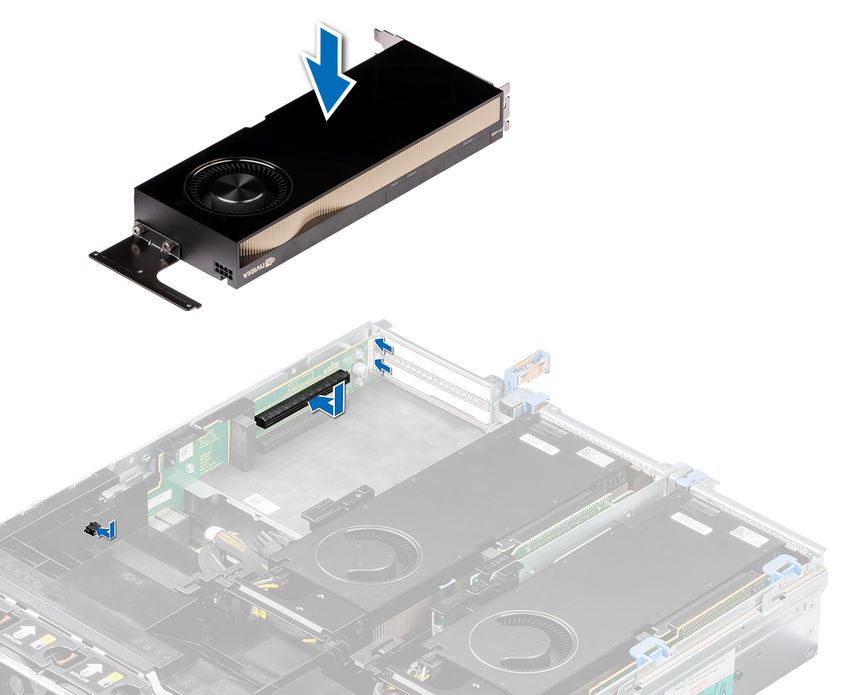
Standby power
Dell products with standby power must be unplugged before you open the case. Systems that incorporate standby power are
essentially powered while turned off. The internal power enables the system to be remotely turned on (wake on LAN) and
suspended into a sleep mode and has other advanced power management features.
Unplugging, pressing and holding the power button for 15 seconds should discharge residual power in the system board.

Bonding
Bonding is a method for connecting two or more grounding conductors to the same electrical potential. This is done through
the use of a field service electrostatic discharge (ESD) kit. When connecting a bonding wire, ensure that it is connected to bare
metal and never to a painted or non-metal surface. The wrist strap should be secure and in full contact with your skin, and
ensure that you remove all jewelry such as watches, bracelets, or rings prior to bonding yourself and the equipment.

Electrostatic discharge—ESD protection
ESD is a major concern when you handle electronic components, especially sensitive components such as expansion cards,
processors, memory DIMMs, and system boards. Very slight charges can damage circuits in ways that may not be obvious, such
as intermittent problems or a shortened product life span. As the industry pushes for lower power requirements and increased
density, ESD protection is an increasing concern.
Due to the increased density of semiconductors used in recent Dell products, the sensitivity to static damage is now higher than
in previous Dell products. For this reason, some previously approved methods of handling parts are no longer applicable.
Two recognized types of ESD damage are catastrophic and intermittent failures.
● Catastrophic – Catastrophic failures represent approximately 20 percent of ESD-related failures. The damage causes
  an immediate and complete loss of device functionality. An example of catastrophic failure is a memory DIMM that has
  received a static shock and immediately generates a "No POST/No Video" symptom with a beep code emitted for missing or
  nonfunctional memory.
● Intermittent – Intermittent failures represent approximately 80 percent of ESD-related failures. The high rate of
  intermittent failures means that most of the time when damage occurs, it is not immediately recognizable. The DIMM
  receives a static shock, but the tracing is merely weakened and does not immediately produce outward symptoms related to
  the damage. The weakened trace may take weeks or months to melt, and in the meantime may cause degradation of memory
  integrity, intermittent memory errors, etc.
The more difficult type of damage to recognize and troubleshoot is the intermittent (also called latent or "walking wounded")
failure.
Perform the following steps to prevent ESD damage:
● Use a wired ESD wrist strap that is properly grounded. The use of wireless anti-static straps is no longer allowed; they do not
   provide adequate protection. Touching the chassis before handling parts does not ensure adequate ESD protection on parts
   with increased sensitivity to ESD damage.
● Handle all static-sensitive components in a static-safe area. If possible, use anti-static floor pads and workbench pads.
● When unpacking a static-sensitive component from its shipping carton, do not remove the component from the anti-static
   packing material until you are ready to install the component. Before unwrapping the anti-static packaging, ensure that you
   discharge static electricity from your body.
● Before transporting a static-sensitive component, place it in an anti-static container or packaging.

ESD field service kit
The unmonitored Field Service kit is the most commonly used service kit. Each Field Service kit includes three main components:
anti-static mat, wrist strap, and bonding wire.

Components of an ESD field service kit
The components of an ESD field service kit are:
● Anti-Static Mat – The anti-static mat is dissipative and parts can be placed on it during service procedures. When using an
   anti-static mat, your wrist strap should be snug and the bonding wire should be connected to the mat and to any bare metal

6       Field service information
on the system being worked on. Once deployed properly, service parts can be removed from the ESD bag and placed directly
     on the mat. ESD-sensitive items are safe in your hand, on the ESD mat, in the system, or inside a bag.
●    Wrist Strap and Bonding Wire – The wrist strap and bonding wire can be either directly connected between your wrist
     and bare metal on the hardware if the ESD mat is not required, or connected to the anti-static mat to protect hardware that
     is temporarily placed on the mat. The physical connection of the wrist strap and bonding wire between your skin, the ESD
     mat, and the hardware is known as bonding. Use only Field Service kits with a wrist strap, mat, and bonding wire. Never
     use wireless wrist straps. Always be aware that the internal wires of a wrist strap are prone to damage from normal wear
     and tear, and must be checked regularly with a wrist strap tester in order to avoid accidental ESD hardware damage. It is
     recommended to test the wrist strap and bonding wire at least once per week.
●    ESD Wrist Strap Tester – The wires inside of an ESD strap are prone to damage over time. When using an unmonitored
     kit, it is a best practice to regularly test the strap prior to each service call, and at a minimum, test once per week. A
     wrist strap tester is the best method for doing this test. If you do not have your own wrist strap tester, check with your
     regional office to find out if they have one. To perform the test, plug the wrist-strap's bonding-wire into the tester while it is
     strapped to your wrist and push the button to test. A green LED is lit if the test is successful; a red LED is lit and an alarm
     sounds if the test fails.
●    Insulator Elements – It is critical to keep ESD sensitive devices, such as plastic heat sink casings, away from internal parts
     that are insulators and often highly charged.
●    Working Environment – Before deploying the ESD Field Service kit, assess the situation at the customer location. For
     example, deploying the kit for a server environment is different than for a desktop or portable environment. Servers are
     typically installed in a rack within a data center; desktops or portables are typically placed on office desks or cubicles. Always
     look for a large open flat work area that is free of clutter and large enough to deploy the ESD kit with additional space to
     accommodate the type of system that is being repaired. The workspace should also be free of insulators that can cause an
     ESD event. On the work area, insulators such as Styrofoam and other plastics should always be moved at least 12 inches or
     30 centimeters away from sensitive parts before physically handling any hardware components
●    ESD Packaging – All ESD-sensitive devices must be shipped and received in static-safe packaging. Metal, static-shielded
     bags are preferred. However, you should always return the damaged part using the same ESD bag and packaging that the
     new part arrived in. The ESD bag should be folded over and taped shut and all the same foam packing material should be
     used in the original box that the new part arrived in. ESD-sensitive devices should be removed from packaging only at an
     ESD-protected work surface, and parts should never be placed on top of the ESD bag because only the inside of the bag is
     shielded. Always place parts in your hand, on the ESD mat, in the system, or inside an anti-static bag.
●    Transporting Sensitive Components – When transporting ESD sensitive components such as replacement parts or parts
     to be returned to Dell, it is critical to place these parts in anti-static bags for safe transport.

ESD protection summary
It is recommended that all field service technicians use the traditional wired ESD grounding wrist strap and protective anti-static
mat at all times when servicing Dell products. In addition, it is critical that technicians keep sensitive parts separate from all
insulator parts while performing service and that they use anti-static bags for transporting sensitive components.

Transporting sensitive components
When transporting ESD sensitive components such as replacement parts or parts to be returned to Dell, it is critical to place
these parts in anti-static bags for safe transport.

Lifting equipment
Adhere to the following guidelines when lifting heavy weight equipment:
   CAUTION: Do not lift greater than 50 pounds. Always obtain additional resources or use a mechanical lifting
   device.
1. Get a firm balanced footing. Keep your feet apart for a stable base, and point your toes out.
2. Tighten stomach muscles. Abdominal muscles support your spine when you lift, offsetting the force of the load.
3. Lift with your legs, not your back.
4. Keep the load close. The closer it is to your spine, the less force it exerts on your back.
5. Keep your back upright, whether lifting or setting down the load. Do not add the weight of your body to the load. Avoid
   twisting your body and back.
6. Follow the same techniques in reverse to set the load down.

                                                                                                 Field service information           7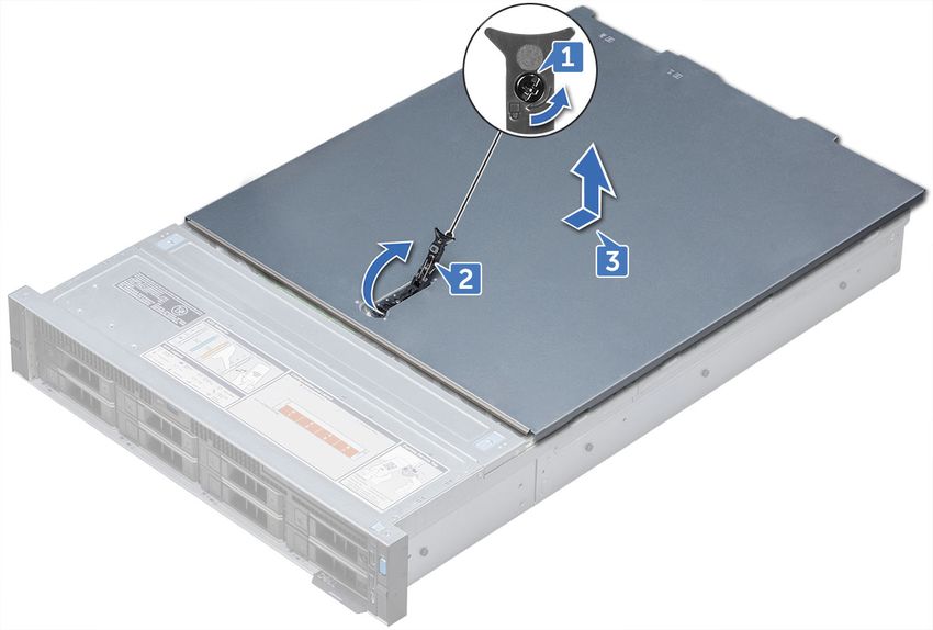
Recommended tools
Table 1. Recommended tools and optional tools
Recommended tools Optional tools
● Key to the system keylock ● Needle-nose pliers to disconnect cables and connectors in
● #1 and #2 Phillips screwdriver hard-to-reach locations
● T30 and T8 Torx screwdrivers ● Small flat-head screwdriver to disconnect small cables
● Wrist-grounding strap connected to the ground from boards
● ESD Mat
Disassembly and reassembly
The following sections contain the procedures for removing and replacing system components.
Front Bezel
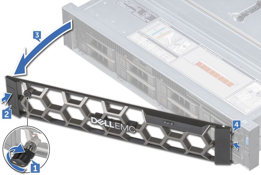
Removing the optional front bezel
Steps
1. Locate and remove the bezel key.
NOTE: The bezel key is attached to the LCD bezel package.
2. Unlock the bezel by using the key.
3. Press the release button to release the bezel, and pull the left end of the bezel.
4. Unhook the right end, and remove the bezel.
8 Field service information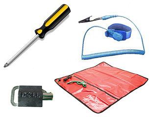
Installing the optional front bezel

Steps
1. Locate and remove the bezel key.
        NOTE: The bezel key is attached to the LCD bezel package.

2. Align and insert the right end of the bezel onto the system .
3. Press the release button and fit the left end of the bezel onto the system.
4. Lock the bezel by using the key.

System cover

Removing system cover

Prerequisites
1. Turn off the system, including any attached peripherals.
2. Disconnect the system from the electrical outlet and disconnect the peripherals.

Steps
1. Using a flat head screwdriver, rotate the latch release lock counter clockwise to the unlocked position.
2. Lift the latch till the system cover slides back and the tabs on the system cover disengage from the slots on the system.
3. Hold the cover on both sides, and lift the cover away from the system.

                                                                                             Field service information         9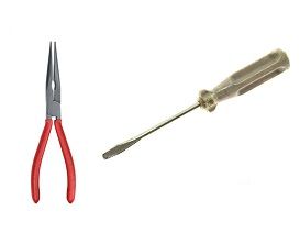
Installing system cover

Prerequisites
1. Ensure that all internal cables are routed correctly and connected, and no tools or extra parts are left inside the system.

Steps
1. Align the tabs on the system cover with the slots on the system.
2. Push the system cover latch down.
3. Using a flat head screwdriver, rotate the latch release lock clockwise to the locked position.

Next steps
1. Reconnect the peripherals and connect the system to the electrical outlet.
2. Turn on the system, including any attached peripherals.

GPU Host Card Installation
This section describes the following hardware installation processes

NVIDIA A6000 Graphics Card Installation

Steps
1. Connect the GPU power cable to the connector on the system board.
        NOTE:

        While installing a GPU on riser 1, connect the GPU power cable to the connector on riser 1 and route the cable through
        the slot on the GPU air shroud.

        While installing a GPU on risers 2 or riser 3, connect the GPU power cable to the connector on the system board.

10      Field service information
2. Connect the other end of the GPU power cable to the GPU.
3. Lift the expansion card latch and remove the filler bracket.
NOTE: You must install a filler bracket over an empty expansion card slot to maintain Federal Communications
Commission (FCC) certification of the system. The brackets also keep dust and dirt out of the system and aid in
proper cooling and airflow inside the system.
NOTE: The filler bracket is necessary to maintain proper thermal conditions.
4. Align the connector on the GPU with the connector on the riser.
5. Insert the GPU into the riser until it is fully seated.
6. Press the PCIe lock on the GPU air shroud and riser to release the PCIe card holder latch.
NOTE: Ensure that the GPU edges are seated properly in the GPU air shroud slot and PCIe card holder latch to secure
the GPU in place.
7. Close the expansion card latch.
Figure 1. Installing GPU 1
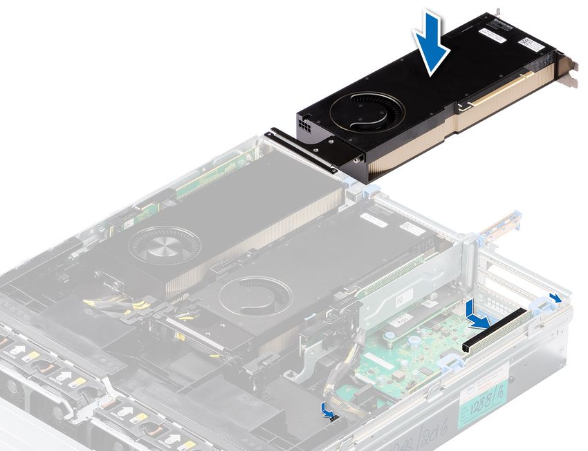
Field service information 11Figure 2. Securing GPU 1
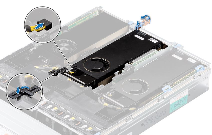
Figure 3. Installing GPU 2
12 Field service informationFigure 4. Securing GPU 2
Figure 5. Installing GPU 3
Field service information 13Figure 6. Securing GPU 3 14 Field service information
3
                                     Getting help and contacting Dell
Self-help resources
You can get information and help on Dell products and services using these self-help resources:

Table 2. Self-help resources
Self-help resources                                              Resource location
Information about Dell products and services                     www.dell.com
My Dell app

Tips

Contact Support                                                  In Windows search, type Contact Support, and press
                                                                 Enter.
Online help for operating system                                 www.dell.com/support/windows
Access top solutions, diagnostics, drivers and downloads, and    Your Dell computer is uniquely identified by a Service Tag or
learn more about your computer through videos, manuals and       Express Service Code. To view relevant support resources for
documents.                                                       your Dell computer, enter the Service Tag or Express Service
                                                                 Code at www.dell.com/support.
                                                                 For more information on how to find the Service Tag for your
                                                                 computer, see Locate the Service Tag on your computer.

Dell knowledge base articles for a variety of computer           1. Go to www.dell.com/support.
concerns                                                         2. On the menu bar at the top of the Support page, select
                                                                    Support > Knowledge Base.
                                                                 3. In the Search field on the Knowledge Base page, type the
                                                                    keyword, topic, or model number, and then click or tap the
                                                                    search icon to view the related articles.

Contacting Dell
To contact Dell for sales, technical support, or customer service issues, see www.dell.com/contactdell.
    NOTE: Availability varies by country/region and product, and some services may not be available in your country/region.

    NOTE: If you do not have an active Internet connection, you can find contact information about your purchase invoice,
    packing slip, bill, or Dell product catalog.

                                                                                    Getting help and contacting Dell          15
You can also read