Design Analysis and Calculations for Economical Electric Go-kart
←
→
Page content transcription
If your browser does not render page correctly, please read the page content below
© April 2021| IJIRT | Volume 7 Issue 11 | ISSN: 2349-6002

Design Analysis and Calculations for Economical Electric
                       Go-kart

                                               Sahil dalal1, Arpit James2
                   1,2
                         Students, B-tech, Dept. of Mechanical engineering, ADGITM, GGSIPU

Abstract - 40% of the world’s pollution is caused by        Art ingles was a veteran hot rod and race car builder at
automobiles which run on either petrol or diesel.           Kurtis Kraft in California4. In the starting karting was
Emergent gases like CO2, CO, SOx etc. from cars play        mainly used for the leisure motorsport enjoyed by the
an essential role in global warming.so basically it is
                                                            airmen during the World War period. It quickly caught
crucial to design such vehicles which are entirely eco-
                                                            in the eyes of the manufacturing corporation and being
friendly, do not produce harmful gases and are cost-
effective.                                                  the first company to manufacture. It produced go-kart
This paper aims to design simple Go-kart which runs         for two years with profits.11
totally on electric power. The primary purpose behind
the design and development of the electric Go-kart is to
make it simple in design, making it simple in working for
non-professional racers, available at a low price and
suitable for everyone.

                  INTRODUCTION

Go-kart is four-wheeled mini vehicles, which was
used in western countries (united states)4. Art Ingles4
invented it. A Go-kart is a small four-wheeled mini car
without suspension and differential axle. It has a low                 Fig.1 Art ingles with first go-kart
center of gravity the same as F1 cars. Go-kart is a         Although it was originated in America soon later,
simple four-wheeled, small engine or electric motor,        other countries from all over the world took an interest
single-seated racing car used mainly in united states.      in it. Today, Karting is governed by the CIK-FIA
They initially created in the 1950s post-war period by      (founded in 1958)11 Main components of the Go-kart
airmen as a way to pass the spare time. a Go-kart by        are chassis, steering, wheels, engine, battery (electric
definition has no suspension and no differential. They      Go-kart), motor (electric Go-kart) and E.C.U. (electric
are usually raced on scaled-down tracks but are             Go-kart). These are the main components’, which are
sometimes driven as entertainment or as a hobby by          essential for every go-kart.
non-professionals.
Go-kart bears a resemblance to formula one cars1, but       Technical specification:
they are not as fast as standard F1 cars. And also, are     Dimension
very cost-effective as compared to F1 cars in all           Overall length:1866.9 mm
aspects.                                                    Overall width: 1112.5 mm
Nowadays, Go-kart is primarily used for karting             Front track width: 965.2 mm
events, professional races, fun for kids and hobbies.       Wheelbase: 1270 mm
Go-kart is far cheaper than standard F1 cars in terms       Ground clearance: 46.99 mm
of manufacturing, fabrication, repairing and events. It
is also far safer than a regular F1 car.                    Battery specification
                                                            Battery type: rechargeable battery
              LITERATURE REVIEW                             Current: 14.5ah

IJIRT 150987                 INTERNATIONAL JOURNAL OF INNOVATIVE RESEARCH IN TECHNOLOGY                        262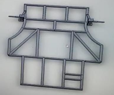
© April 2021| IJIRT | Volume 7 Issue 11 | ISSN: 2349-6002
Voltage:36v
Charging time:10hours
Motor specification
Power: 500w
Voltage: 36v
Rpm: 3000 rpm
Transmission
Transmission type: simple chain
Driver sprocket: 42 teeth
Driven sprocket: 14 teeth
Tire specification Fig2. Design of chassis
Front diameter: 10 inches
Rear diameter: 11 inches Material Selection
Rim size: 5 inches The material that has been used for the chassis is AISI
1018. AISI 1018 mild/low carbon steel has excellent
Steering specification weldability, produces a uniform and harder case, and
Steering type: Ackermann steering it is considered the best steel for carburized parts. AISI
Steering ratio: 1.4:1 1018 mild/low carbon steel offers a right balance of
Turning angle: 2.7 m toughness, strength and ductility4. AISI 1018 hot
rolled steel has significant mechanical properties,
Frame design: The frame design is the most integral improved machining characteristics and has a high
part of every Go-kart. It forms the base of the project. Brinell hardness measure.
a. It should not bend. Specific manufacturing controls are used for surface
b. It should have torsional rigidity. preparation, chemical composition.
c. It should have lightweight.
The objective of the design of this project includes all Material specification
the above points. Element Content
Carbon, C 0.14 - 0.20 %
Iron, Fe 98.8-99.26%
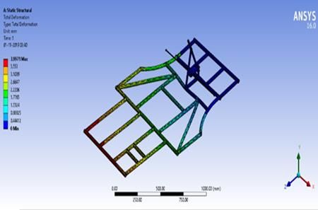
COMPUTER-AIDED DESIGN (CAD): The chassis Manganese, Mn 0.60 - 0.90 %
is designed on Solid works 2018. the chassis is Phosphorous, P ≤ 0.040 %
designed for a rear-mounted electric motor. The
chassis has the minimum wheelbase of mm and small Table.1 Chemical composition5
front track width. The motor and the driver are not in Mechanical Properties Imperial Metric
Hardness, Brinell 126 126
the same line and are separated by the firewall. The
Tensile Strength 440 MPa 63800 psi
design includes the mounting features if the following. Yield Strength 370 MPa 53700 psi
a. Motor mounting Reduction of Area 40.0 % 40.0 %
b. Steering assembly Modulus of Elasticity 205 GPa 29700 ksi
c. Bodyworks Bulk Modulus 140 GPa 20300 ksi
Poisson Ratio 0.290 0.290
d. Rear-axle assembly
Machinability 70 % 70 %
e. Driver seat Table.2 Mechanical properties5
f. Battery mounting
g. Electronic controller unit mounting COMPUTER-AIDED ENGINEERING (CAE) &
The design of the chassis is made keeping in mind the OPTIMISATION
dynamics forces and other external forces on the For C.A.E. of the go-kart frame, we performed
chassis for high performance Requirement. different analyses on ANSYS 14.5. Different load
IJIRT 150987 INTERNATIONAL JOURNAL OF INNOVATIVE RESEARCH IN TECHNOLOGY 263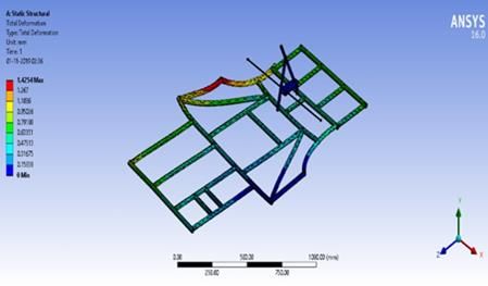
© April 2021| IJIRT | Volume 7 Issue 11 | ISSN: 2349-6002

cases were considered to carry out a thorough analysis       hits our vehicle from the rear. The load is calculated
of the frame, which included front impact, rear impact       by using the equation F=m*v/t.
and side-impact. Based on finite-element and through
advanced analysis and optimization algorithms. Mesh
size of 10mm was selected to facilitate accurate results
and save solving time. R-TRIA and QUAD elements
were selected for meshing. Geometry was modelled by
using the shell model as shell model can include shear
deformations and local buckling effects. SHELL 181
and SHELL 281 were the element types we have used.
Beam model has not opted as shear deformation, and
local buckling effects play a crucial role in the analysis
of the done on ANSYS MECHANICAL APDL
                                                                               Fig.5 rear impact
Solver.
                                                                               FRONT       REAR        SIDE
Front-impact test: The case considered during the front
impact of the vehicle is that when our vehicle of 150          Impact Force     5000 N       5000 N      4000 N
kg is moving with its maximum velocity of 60 kmph,                Total         4.2 mm      3.35 mm     1.65 mm
                                                               Deformation
it hits a stationary object from the front. The load is
                                                                  F.O.S.          1.21        1.02         1.1
calculated by using the equation F=m*v/t.
                                                             Table.3 Applied forces

                                                             Torsional rigidity
                                                             To measure the overall frame rigidity, torsional
                                                             rigidity analysis was conducted through F.E.A. The
                                                             objective of the torsional rigidity analysis was to
                                                             manipulate the chassis design within the F.E.A.
                                                             software to increase the amount of torque per degree
                                                             of chassis deflection. By theoretically increasing this
                                                             value, the actual vehicle could have the ability to be
                                                             more torsion-ally rigid, making it able to withstand
                   Fig.3 front impact                        more intensive without failure. To achieve this
Side impact test: The case considered during side            analysis, a simulated torque of which is equivalent to
impact is that during the vehicle is stationary and          the gross weight is calculated, i.e. Gross weight = 150
another vehicle having a mass of 150 Kg travelling           kg and the equivalent force that is –
with a velocity of 16.66m/s hits it from the side.           F = M x (V^2)/R
                                                             F = 150 × 8.32/2
                                                             F = 2697.5 N
                                                             The calculated force is placed on two knuckle ends of
                                                             the frame while the rear of the frame was constrained.
                                                             The deformation of the analysis was coming out to be
                                                             41.34 mm.
                                                             Hence according to the result obtained the frame
                                                             would be torsionally rigid.

                                                                              CALCULATIONS
                  Fig.4 Side impact
Rear impact: The case considered during the rear
                                                             1. Speed calculations
impact of the vehicle is that when our vehicle is
                                                             Gear ratio (G.R.) = Zg/Zp
stationary, and another vehicle with a mass of 150kg
                                                                       =42/14 = 3
and moving with its maximum velocity of 60 kmph

IJIRT 150987               INTERNATIONAL JOURNAL OF INNOVATIVE RESEARCH IN TECHNOLOGY                            264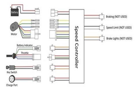
© April 2021| IJIRT | Volume 7 Issue 11 | ISSN: 2349-6002

Unloaded motor rpm = 3100 rpm                       • Length of chain (L)7
Loaded rpm = 2800rpm                                Let’s consider the distance between sprocket and
Tire radius = 278/2=139mm                           pinion 30 times the pitch
                                                    =30P = 30*12.07= 362mm
• Loaded                                            Due to the initial slag, center distance is reduced by
Speed= (Nmotor/G.R.) * 3.14*(2R/60)                 the 2mm-5mm. we take 4mm
= (2800/3) *3.14*(2*139/60)                         X= 362-4= 358mm
Speed= 13.56m/s
Speed=48.816km/hr                                   Number of chain links
                                                    K=((T1+T2)/2)+(2X/P)+((T2-T1)/2*3.14)^2 * P/X
• Unloaded                                          K=((42+14)/2)+(2*358/12.07)+
Speed=(Nmotor/G.R.) * 3.14*(2R/60)                  ((42-14)/2*3.14)2*12.07/358
= (3100/3) *3.14*(2*139/60)                         K=87.975
Speed=15.028m/s                                     L=K*P= 87.975*12.07= 1.06M= 1061MM
Speed= 54.10km/hr
                                                    3. Braking calculations1
2. Go-kart axle rotational speed                    We chose tandem master cylinder, pulsar180 rotor and
We chose 42 driver teeth sprocket and               apache rear calliper. DOT3 oil is used for the braking
14 driver teeth /R428-108 L chain                   oil
Pitch(p)=12.07mm                                    Gross wt.: 180*9.81= 1765.8 N
T2 = 42                                             Pedal ratio: 5:1
T1= 14                                              The normal force of pedal:180*5=900N
N1= 3100                                            Tandem master cylinder (TMC) bore:19.05
N2=?                                                Area of T.M.C.:286mm2
                                                    Calliper diameter:25.4
T2/T1=N1/N2                                         Area of calliper:1013.85 mm2
42/14=3100/N2
N2 = 1033 rpm                                       • Brake line pressure (B.L.P.)
w.r.t 1033 R428 means p=12.07                       BLP= (900*5)/ (3.14/4(19.05) 2)
                                                    =15.78 N/mm2
• Velocity ratio= N1/N2
=3100/1033                                          • Clamping force (C.F.)
=3.0009 ~ 3                                         CF= BLP* area of calliper* no. of a piston
=3                                                  = 15.78*1013.85*2
• Power=rated power*service factor                  =31997.1 N
Ks=K11*K2*K3
=1.25*1*1                                           • Rotating force (R.F.)
=1.25                                               RF= CF*no. of pistons*coefficient of friction
Rated power= 500=0.5KW                              =31997.1*2*0.4
Power= 0.5*1.25                                     =25597.68 N
      =0.625 KW
      =625W                                         • Braking torque (B.T.)
• Diameter of pinion gear                           BT= RF*effective disc radius
D1=(P/sin(180/T1))                                  =25597.6*0.087
   = (12.07/sin (180/14))                           =2226.9 Nm
D1= 60.35mm
 Similarly                                          • Braking force (B.F.)
D2=201.16mm                                         BF= BT/tire radius

IJIRT 150987            INTERNATIONAL JOURNAL OF INNOVATIVE RESEARCH IN TECHNOLOGY                   265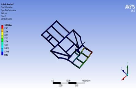
© April 2021| IJIRT | Volume 7 Issue 11 | ISSN: 2349-6002

= (2226.9/0.41) *0.8                                  Charging time of the battery= AHR/CC
=4345.36                                              AHR= ampere-hour rating
                                                      CC= charging current
• Deceleration                                          = 145/1.45
BF= -ma                                                 =10 hours
a= -BF/m
= 4345.36/180                                         2. Practical case (considering 50% losses)
=-24.1 m/s2                                           In this battery, 50% losses occur.
                                                      Actual required charging time = ideal charging time +
• Stopping distance                                   additional charging time when losses occur
V2 – u2 = 2aS                                         =10 + (50/100) *10
V=0 U=15.02                                           = 15 hours
S= -(15.02) 2/-(2*24.16)
S= 4.68 m                                             • The discharge time of the battery
                                                      1. Ideal case
4. Steering calculations                              Battery voltage = 36 v
Track width (W)= 964 mm                               Applied voltage=1000v
1/tan Ɵo - 1/tan Ɵi = W/B
Ɵo=38o Ɵi = 27o                                       Discharge time = AHR*battery voltage/
1/tan 38o - 1/tan 27 = 964/B                                            Applied voltage
B= 1377.14mm                                                         = 14.5*36/1000
B= wheel base                                                        = 0.522 hours
 b= 610mm                                             2. Practical case (considering 50% losses)
R1 = B/tan Ɵi + W/2                                   Actual discharge time= ideal discharge time - loss in
   = (1377.14/tan 88) + (964/2)                       discharge time when loss occurs.
   =2244.65                                           =0.522 - 0.522* (50/100)
                                                      =0.261 hour
•
    Turning radius= √ R2 + b2
              = 2326mm                                           ELECTRICAL CONNECTIONS

•   Outer angle                                       The central unit of the electrical system is E.C.U.
   =(Tanx=L)/R-d/2                                    (electronic control unit). It consists of different port for
=1377.14/ (2326-1377.14/2)                            battery, motor, on/off switch, reverse, brake, lights etc.
=29.03o                                               battery, accelerator pedal, on/off switch and motor are
                                                      connected to derailleur in E.C. U. The battery needs to
• Inner angle                                         be connected in series if we were using 12v*3 batteries
=(Tanx=L)/R+d/2                                       but should be connected normally if we were using one
=1377.14/ (2326+1377.14/2)                            unit of a battery.
= 20.8o

5. Battery calculation
• Charging of the battery
1. Ideal case (neglecting losses)
Amp-hour rating of the battery=14.5ah Charging
current should be 10% of it of Ah     rating of the
battery
Charging current (CC)= (10/100) *14.5
                      =1.45 A
                                                                    Fig.5 electrical connections

IJIRT 150987               INTERNATIONAL JOURNAL OF INNOVATIVE RESEARCH IN TECHNOLOGY                        266
© April 2021| IJIRT | Volume 7 Issue 11 | ISSN: 2349-6002
RESULT AUTHOR DETAIL
The design of electric Go-kart has been completed 1. Sahil Dalal – Student of final year, B-tech, dept of
successfully as planned. It is designed according to the mechanical engineering, ADGITM, Former
calculations and can handle the weight and able to member of SAE BAJA 2018 and NEKC. Scored
achieve speed around 35-40 kmph. first rank in BAJA virtual 2018.
2. Arpit James – Student of final year, B-tech, dept
CONCLUSIONS of mechanical engineering, ADGITM, Former
member of SAE BAJA 2018 and NEKC. Scored
Through this paper, we aimed to design a vehicle with first rank in BAJA virtual 2018.
a combination of both electronics as well as
mechanical models and also to present it aesthetically
and ergonomically strong. With a very light and robust
frame, pure steering, efficient braking system and
optimum power to mass ratio, the kart can easily fulfil
all the static and dynamic tests put through.
REFERENCES
[1] Prof. Ambeprasad Kushwaha1 & Prof. Avinash
Chavan, Tapeshwar A. Das, Shubham S.
Kenjale4, Jay A. Patel, Pradeep R. Prajapati
“DESIGN AND FABRICATION OF COST-
EFFECTIVE ELECTRIC GO-KART”
International Research Journal of Engineering
and Technology (IRJET) e-ISSN: 2395-0056, p-
ISSN: 2395-0072, Volume: 05 Issue: 04 | Apr-
2018 www.irjet.net
[2] Nipun Jalhotra, Shivam sethia, Rahul Sharma and
Himanshu Singh, IJREAS VOLUME 5, ISSUE 7
(July 2015) (ISSN 2249-3905), International
Journal of Research in Engineering and Applied
Sciences (IMPACT FACTOR – 5.981)
[3] Carbikesketch.com/CHASSIS
[4] https://www.polepositionraceway.com/blog/what
-karting/
[5] https://www.azom.com/article.aspx?ArticleID=6
115
[6] Design Machine Elements by V B Bhandari
[7] Machine Design by R S Khurmi
[8] https://auto.howstuffworks.com/auto-
racing/motorsports/go-kart-racing.htm
[9] www.ehow.com
[10] www.kartingbuilding.net
[11] Aberdeen lim jian rong, low fiber glass go kart,
Universiti tunku abdul Rahman, ME-2011-
0705783-1.
IJIRT 150987 INTERNATIONAL JOURNAL OF INNOVATIVE RESEARCH IN TECHNOLOGY 267You can also read