Hydraulic Trailer Jack Installation and Operation Guide Hydraulic Trailer Jack AJ Dual Leg
←
→
Page content transcription
If your browser does not render page correctly, please read the page content below
1-800-846-9659
www.equalizersystems.com
Hydraulic Trailer Jack
Installation and
Operation Guide
October 2010
Revision January 2021
Hydraulic Trailer Jack
AJ Dual Leg
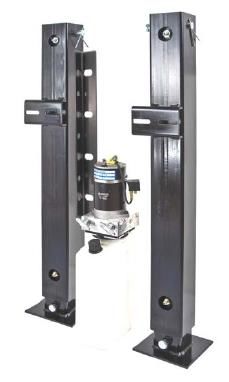
General Description
• Dual leg trailer jack
• Lifting capacity: 14,000 lbs
• Stroke: 24 inches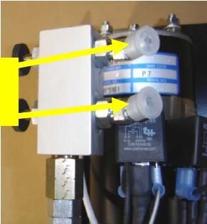
Installation
      Tools Required for Installation

  •   Ratchet, sockets and wrench set
  •   Wire cutters/crimpers
  •   Electric drill and bits
  •   Screw gun bit
  •   Welding equipment (if welding leg in place)

      Additional Parts Needed for Installation

  • # 6 gauge power wire (to connect battery +12V to the pump)
  • # 6 gauge ground wire (to connect battery –12V ground to pump)
  • # 6 gauge ring terminals
  • Wire loom and clips (to secure and protect harness and switch)
  • Self tapping screws or pop rivets (to secure loom clips)
  • Wire ties
  • Automatic transmissinon fluid (multi purpose or Dexron) (aprox 6 qts) to fill the resivior and
      system

Jack Mounting
The AJ style jacks are available in “bolt on” or “weld on” configurations (depending on the
mounting option ordered for the system). Mounting provisions must be designed with
adequate strength to sustain trailer weight and jack lifting capacity. If bolting the jack
in place, ensure the use of appropriate size for the application (½” or 3/8”) and
quantity of mounting hardware. The use of Grade 8 bolts is recommended. Welding
the jack in place requires sound welding practices.

The jacks should be mounted so that when the trailer is level (while mounted to the tow
vehicle) there is a Minimum of 10 inches of Ground Clearance. This is usually
achieved by mounting the jacks so that the foot is slightly below the bottom edge of
trailer. The bottom of the footpads should not be lower than any other item mounted on
the trailer.
Pump Mounting
The pump is mounted with threaded studs that are fitted to the pump body. Flange
nuts are provided. The pump is designed to be mounted vertically only.

Switch Harness and Hydraulic Lines
The jack system has been shipped with all necessary switchgear, harnesses and
hydraulic lines. These items are specifically engineered to operate your system and
should not be altered in any manner.
Modification of any factory-supplied item may result in the denial of all
Warranty claims.

EQ009R3
                                               2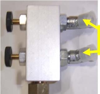
Switchgear
The unit may have been provided with a key switch in the switchgear box (depending
on the option ordered). If unit is not supplied with a key switch, the +12v battery lead
must be fed through a power disconnect switch to fully isolate the system during
travel or inactivity. Minimum disconnect switch rating must be 80 ampere DC. Switchgear is
plugged into the system harness through a weather resistant connector (shown in
Fig.1)

                                                   Fig.1
                                                   Weather Resistant Connector

Battery Connections
Battery Lead (+12volts): Attach a # 6-gauge (minimum) wire between the positive
+12 volt terminal on the battery and the plus ( + ) terminal on the contactor; shown in
Fig.2
If circuit protection is required, install an 80 amp (minimum) circuit breaker.

                                                                  Attach battery negative (ground) to
        Fig.2                                                               contactor here

                                                                      Attach +12V Positive from
                                                                            Power Supply
                                                                             (6 gage min)

 Pump Ground (-12volts): Attach a # 6 gauge (minimum) wire between the negative
-12 volt terminal on the battery and the negitive terminal on the contactor as shown in Fig.2.
 These unts will not ground thru the mounting. The decribed ground/negitive battery to
 contactor connection must be made.

                                              3.
Reversing Contactor Wiring Pump 3041 and 3201

Note: on pump # 3201KS the Blue and green wires are reversed
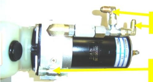
Hydraulic Hose Connections

Connections to Top/ Extend Jack Port:
If equipped with a manual selector valve:
The extend port on the pump is fitted with a manual selector valve extending from
the manifold block. The Selector Valve has Twist Turn Knobs to select jack
operation. The hoses are to be connected from the selector valve to the top fittings
(cap or closed end) of each jack leg.

                                              Connect
                                              to Jack
                                              Top
                                              Fittings

If not equipped with manual selector valve:
The extend port on the pump is fitted dual connection assembly (see below). Hoses
are routed from this assembly to the top fitting (cap or closed end) of each jackleg.
The port is marked with a “T” or “A” near the reservoir.

                                                                         Connect to Jack
                                                                          Top Fittings

                                                                         Connect to Jack
                                                                          Bottom Fittings

Hose Connections Bottom/ Retract Jack Port: The pump retracts port is
equipped with a TEE fitting. The port is marked with a “B” near the reservoir. This
fitting is connected to the bottom fitting of each jack (rod end). It does not matter
which one is left or right.

                                             5
System Purging
Following component installation, this procedure must be performed with the initial
running of hydraulic system. All electrical and hose connections must be completed
before the purging process.
1) Fill the reservoir with Dexron Automatic Transmission Fluid.
2) Make sure the manual selector valves (black trumpet valves), if equipped, are
fully pushed in to the IN/OPEN position to allow proper fluid flow.
3) Remove the Bottom (Retract) hoses from the TEE fitting at the pump and
place them into a clean container. Cap the ends of the TEE fitting on the
pump to ensure that no air or debris can enter.
4) With the Bottom hoses placed in a container, run the pump to fully EXTEND
the jacks(s). Maintain the fluid level in the reservoir approx ½ full. Do not
allow reservoir to run empty. If jacks(s) will not fully extend, crack loose the
upper hose(s) at the jack(s) and run pump to extend until all the air is
expelled. Retighten the hoses and complete the extension of the jack(s).
Continue to maintain the fluid level in reservoir at 1/2 full. Note: normally only
air will be expelled from the disconnected bottom hoses, however, it is
possible some residual oil will be expelled.
5) Reconnect the Bottom (Retract) hoses to the Tee fitting at the pump.
6) Run the pump to RETRACT the jack(s). Maintain the fluid level in reservoir at
¾ full. Do not fill to full until after the legs are fully retracted.
7) If fluid in reservoir appears to be aerated (foaming), allow unit to sit until foam
dissipates (approx 5- 10 minutes).
8) Fully extend and retract jack leg(s) a minimum of 3 times. Allow the air in the
foamed oil to dissipate as needed. Maintain the fluid level in the reservoir as
needed.
Reservoir Breather Cap
Once the system is purged, install the fill/breather cap. Failure to do so will allow
unwanted debris or water into the system.
Fluid Level: When the jack is fully retracted, the fluid level in the reservoir should be
approximately one inch below the fill/breather cap. If fluid needs to be added, use Dexron
automatic transmission fluid (the same as used for a GM automobile).
To Raise and Lower the jacks:
Activate the keyed switch (if equipped), then push and hold the rocker switch in the up
or down position. TRAILER UP to extend the jacks or TRAILER DOWN to retract.
6If the system is equipped with a manual selector valve:
1. Twisting the knob counter clockwise to opens the valve for the desired
jack operation. By turning both knobs out (counter clockwise), the jacks
will operate in tandem. To operate only one jack, close the valve (turn
it fully clockwise) to the jack that is to remain stationary.
2. Operate the switch in the desired direction. Trailer up to extend jacks
or trailer down to retract jacks.
3. Twist the valve knobs to the IN/Closed (clockwise) position for storage
or travel.
When finished, remove the key or operate the manual disconnect to prepare the system
for travel.
The jack will “hold” a position by releasing the switch at any time. There is no need to
take the “weight” off the jack when storing the trailer. Positive check valves in the
system will not allow the jack to “bleed down”.
Warning: With any hydraulic application, holding any position on a cylinder must
be done with safety in mind. Failure in the system may cause the leg to retract or
extend on its own. When working under or near the trailer, always use jack stands
of appropriate rating to support the weight of the trailer.
The keyed switch must be in the off position and the key must be removed when the jack is
not in use and/or when the trailer is in transit. If unit is not supplied with a keyed switch,
the +12v battery lead must be fed through a power disconnect switch to fully isolate the
system during inactivity or travel. The minimum disconnect switch rating must be 80 ampere DC.
7Manual Override
The AJ series pump has provisions for manual override.
Before you begin this
procedure, please read and
understand these
instructions.
Required Items:
End of
Reversible Drill-capable of Motor
producing a minimum of
2000 r.p.m.
1/4” (6mm) Allen Hex
Wrench bit or driver.
To override the jack:
Open Manual selector
valves (if equipped).
Remove the foil seal from
the top of the motor. Use a
small flat head screwdriver if
necessary.
Insert the ¼” (6mm) Allen Override Coupler
Hex key bit on the manual (Under Foil Seal)
override shaft located at the Accepts
top of the motor. 1/4” (6mm) Hex
To Retract: Allen Driver
Run drill in the clockwise
direction at 2000 r.p.m.
(minimum). The jack will
retract.
To Extend:
Run drill in the
counterclockwise direction
at 2000 r.p.m. (minimum).
The jack will extend.8
Problem Solving

The Jacks run for a few seconds, then stops” The battery is weak or battery capacity
is diminished. Charge the battery fully. It may be necessary to “load test” the battery.

“The jacks only run in one direction” Verify appropriate battery voltage. Verify that all
wires are attached appropriately. Verify proper function of the switchgear.

“I push the switch and nothing happens” Ensure both positive (+12V) and negative
(-12V) have adequate connection. Ensure full charge on your battery.
 Ensure that the pump unit is properly connected both positive and negitive to the
battery with a minimum # 6-gauge wire. Check all associated wiring.

Most of the calls to the Equalizer Systems Help Desk are related to low battery voltage

“The jack is jerky when retracting” This may be caused by air in the system, low
fluid level, or incorrect hose installation. To purge leg, add fluid as necessary and
run the leg to full extension and retraction at least twice. If problem persists, call
Equalizer Systems for assistance.

 Fluid Level: When the jack is fully retracted, the fluid level in the reservoir should be
 approximately one inch below the fill cap. If fluid needs to be added, use Dexron
 automatic transmission fluid (the same as used for a GM automobile).

          If your problem is not listed or persists, call Equalizer Systems at
                               1- (800) 846-9659
            Please gain prior authorization for warranty service or repair.

                                              9
Equalizer Systems Limited Warranty Policy
March 2017
1. Only warranty claims with prior written or verbal authorization from Equalizer Systems will be recognized, all other
claims will be denied.
2. Equalizer Systems warrants single and dual jack system components for a period of two years from the date of original
sale of the vehicle. This warranty covers defects in material and workmanship only. Equalizer Systems is not liable for any
damage due to abuse, neglect, misuse, negligence, misapplication, error of operation, accidental or purposeful damage
or damage due to an “act of God” such as, wind or rain damage, flood, lightning or other natural occurrence of the like.
Equalizer Systems limited warranty is applicable to the Equalizer Systems components only and does not apply to the
vehicle, apparatus or property to which it is attached. Warranty parts will be shipped at no charge if the repair is
authorized by an Equalizer Systems representative. Purchased components used in authorized warranty repairs will be
reimbursed at the original purchase price.
3. Labor and freight expenses due to warrantable parts defects or workmanship will be reimbursed for a period of one
year from the date of original sale of the vehicle. Freight expenses will either be prepaid by Equalizer Systems or
reimbursed at the UPS Ground rate only. Any additional shipping charges or requirements are the obligation of the
vehicle owner or service center performing the warranty repair. The owner or service center’s obligation may include
overseas shipping charges, border fees, brokerage fees and any other additional fee of the like.
4. Warranty labor will be reimbursed only for claims that have prior written or verbal authorization from an Equalizer
Systems representative. Warranty labor compensation is required to correspond with the “Warranty Parts Replacement
Time Guideline” published by Equalizer Systems. Any warranty repair not listed on this guideline will require prior
authorization from an Equalizer Systems representative. A reasonable time allowance will be determined by the Equalizer
Systems representative. Any warranty repair that is not listed on this guideline that is performed without prior
authorization will be denied without exception. Time associated with learning about the repair or excessive diagnostic
and installation time will not be reimbursed. Warranty labor will be reimbursed at the authorized service center’s
published shop rate if the rate is reasonable for that region. Overtime labor will not be reimbursed without exception.
5. Labor, parts and freight credit (if applicable) will be sent after the parts are tested and the warranty claim is validated.
Returned parts that are found to be in normal operating condition are not warrantable and will be charged to the owner
or service center. Equalizer Systems reserves the right to charge back the service center for labor claim payments
previously submitted if the installation of the warranted part is found to be inadequate at a later date.
6. Claims will be denied if the date submitted is greater than 30 days from the repair date.
7. Prior authorization is required before parts may be sent back to Equalizer Systems. A Return Authorization Number is
required for items to be accepted.
8. Complete systems are not warranted unless authorized by an Equalizer Systems representative. There are absolutely
no exceptions to this clause.
9. Warranty coverage for parts or systems sold by non-authorized resellers (such as live or internet auctions) will be at the
discretion of Equalizer Systems.
10. Equalizer Systems is not liable for loss of time, manufacturing costs, labor, material, loss of profits, direct or indirect
damages incurred by the vehicle manufacturer.
11. Excessive warranty labor resulting from inadequate access to the Equalizer Systems product will not be reimbursed.
12. Equalizer Systems will not pay a markup on warranty parts unless required by law.
13. Travel expenses, hotel, telephone, fuel or any other expenses of the like are not covered under warranty.
Replacement Parts:
1. Replacement parts are warranted under the same guidelines listed above for the remainder of the original warranty or
90 days, whichever is longer. Proof of warranty repair date and original vehicle purchase date are required.
No additional warranties, expressed or implied, are authorized by Equalizer Systems
This warranty voids all previous issues.
Questions concerning this warranty should be directed to:
Equalizer Systems
55169 CR 3 North
Elkhart, IN 46515
1-(800) 846-9659
1-(574) 266-6083 fax
To activate your warranty, please visit our website at http://equalizersystems.com/service/activate-warranty
EQ009R3You can also read