Structural Design Concept - KISPE Space KS-DOC-01253-01, March 2021 - Open Source Satellite programme
←
→
Page content transcription
If your browser does not render page correctly, please read the page content below
Structural Design Concept
Open Source Satellite 2021

                                           KISPE Space
                                    KS-DOC-01253-01, March 2021
CC BY-SA 4.0: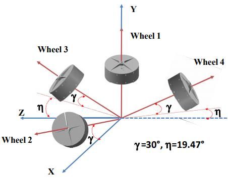
Contents

                               Problem Statement

                               Open Source Satellite Structure Requirements

                               General Spacecraft Structure Requirements

                               Application-Specific Structure Requirements
Open Source Satellite 2021

                               Further questions or want to get involved?
CC BY-SA 4.0:

                                                                              2
OSSAT Structure Design
Problem Statement
What are we trying to do and why?
Open Source Satellite 2021
CC BY-SA 4.0:
3Problem Statement
• The Open Source Satellite (OSSAT) is intended to be an
open source, 25-250 kg microsatellite platform which is
capable of servicing a wide variety of applications.
• The OSSAT structure poses an interesting design
challenge as it needs to be capable of accommodating
different payloads with minimal redesign for different
missions.
• We believe, to achieve the aim of accommodating
various payload types, there should be a clear
delineation between the platform and payload in the
Open Source Satellite 2021
structure.
CC BY-SA 4.0:
4Problem Statement
• Units that do not change between missions will be
placed in the platform area and any equipment that is
required only for individual applications will be placed in
the payload area.
• The structure needs to be designed so
that it is easy to scale depending on the
size and needs of the payload. Payload
Area
• A key objective of the OSSAT
programme is to reduce the size of the
platform. This will be achieved by
Open Source Satellite 2021
integrating as many as possible of the
platform specific units into a single
entity which will be the core avionics. Platform Area
CC BY-SA 4.0:
5Problem Statement
• We are really looking for novel and innovative ideas to solve
our problem. Is there something that can be done that hasn’t
yet been seen before in the space domain? Can we leverage
ideas from other domains?
• No space experience? Don’t worry! We aren’t only looking for
people who have experience in the space industry. There
should be enough information in this pack to point those
without experience in the right direction – and you can always
drop us a line with any questions!
• The designs can be generated in any sensible format, whether
that be sketches, engineering drawings or CAD models. We
are interested in the conceptual design at this stage.
Open Source Satellite 2021
• For those of you who want to flex your CAD muscles then
there are some free CAD packages out there including:
CC BY-SA 4.0:
• OnShape (https://www.onshape.com/en/products/free)
6Open Source Satellite
Structure Requirements
What things do we need to consider?
Open Source Satellite 2021
CC BY-SA 4.0:
7Core Avionics Box (1)
• The OSSAT Core Avionics Box will encompass units that
you would typically find within a satellite, so you only
need to include a single box for this item.
• It will also have built in redundancy so only one of
these boxes will be needed within the concept.
• For those of you who are interested, the OSSAT Core
Avionics Box will include the functionality of the
following components:
• Onboard computer
• GPS receiver
• Magnetorquer driver electronics
• Reaction wheel driver electronics
• Propulsion controller (if required by application)
Open Source Satellite 2021
• Star tracker electronics
• Inertial measurement units
• Transceiver units
Power control and distribution unit
CC BY-SA 4.0:
•
8Core Avionics Box (2)
• The key part of the design of the OSSAT Core Avionics
Box is that it is not to change between missions!
• The items that might change are the peripheral units
described in the platform and payload components list
in the upcoming slides depending on the mission type.
• One idea we had, since this aspect shouldn’t change,
was whether the Core Avionics Box could form an
integral part of the structure, potentially providing
loading paths between the platform and payload
sections.
Open Source Satellite 2021
• This is not to say that this is the only way to provide these
loading paths so interesting alternatives to this idea are
definitely encouraged!
CC BY-SA 4.0:
9Generalised Component List
• To allow you to see what kind of volume is needed for
the platform and payload sections, the following slides
provide descriptions of each of the units needed and
what section they should fall into.
• The descriptions and datasheets are to provide
information to allow you to appropriately size the
various items.
• They are representative parts that we have chosen. At this
stage in our programme we have not yet selected what
peripherals are going to fly. The inclusion of specific units is
intended to be merely for representative purposes and does
not mean that that unit will be used in the final OSSAT
Open Source Satellite 2021
design.
CC BY-SA 4.0:
• We have taken an optical Earth Observation imaging
payload as the starting point for the structural design. 10Platform Component List (1)
Approx.
Unit Quantity Size Notes
Mass (kg)
Core Avionics 1 4.5 Approximate volume of 0.015 m3 The approximate volume for
Box or 15 litres. the avionics box has been
given. The shape of this is
for you to decide!
Reaction 4 See NewSpace System’s NRWA-T065 Tetrahedral configuration
Wheels datasheet reaction wheel - Datasheet using angles provided on
slide 32.
Magnetorquers 3 See NewSpace System’s NCTR-M016 One in each of the
datasheet torque rod - Datasheet spacecraft body axis.
Magnetometers 2 See NewSpace System’s NMRM Generally positioned away
datasheet magnetometer - Datasheet from magnetorquers.
Open Source Satellite 2021
Battery 1 1.5 Representative box with
dimensions: 170 x 200 x 100 mm
CC BY-SA 4.0:
• These items should all be housed within the platform area.
11Platform Component List (2)
Approx.
Unit Quantity Size Notes
Mass (kg)
Separation 1 See 15 inch separation system - Fixed to the centre of an
System datasheet Datasheet external face of the OSSAT.
Solar Array - 3 kg/m2 Use the following solar cell if you See slide 14 for more
want to make a detailed solar information.
panel model - Datasheet
Star Tracker 2 See Auriga SA – Datasheet (only need Positioned according to
Optical Head datasheet to model the star tracker optics) slide 30.
Sun Sensors 4 See NewSpace System’s NCSS-SA05 Positioned according to
datasheet Datasheet slide 30.
S-band Antenna 4 See Datasheet Positioned according to
datasheet slide 28.
GPS Antenna 1 See NewSpace System’s NANT-PCLT1 Positioned according to
Open Source Satellite 2021
datasheet Datasheet slide 28.
• These items should all be housed within the platform area.
CC BY-SA 4.0:
12Earth Observation Payload
Approx.
Unit Quantity Size Notes
Mass (kg)
Imaging 1 25 A cylindrical volume with height: This payload volume
Payload 750 mm and diameter: 400 mm. encompasses all of the
One circular face of the cylinder payload electronics and
must have an external field-of- processing units and can
view. therefore be modelled as a
simple cylinder.
X-band 2 1.0 Representative box with Should be placed in payload
Transceiver dimensions: 175 x 120 x 50 mm area.
Payload Power 1 See AAC Clyde’s Starbuck Micro - A power interface for the
Control Unit datasheet Datasheet payload. Should be placed
in payload area.
Payload Data 1 1.5 Representative box with Should be placed in payload
Storage dimensions: 150 x 75 x 30 mm. area.
Payload Battery 1 1.5 Representative box with A payload battery for
Open Source Satellite 2021
dimensions: 170 x 200 x 100 mm additional payload power
requirements. Should be
placed in payload area.
CC BY-SA 4.0:
X-band antenna 2 See SpaceTeq’s Xhorn-18 antenna : Positioned according to
datasheet Datasheet slide 28.
• These items should all be housed within the payload area. 13Minimum Solar Panel Area
• In order to generate power, the OSSAT
will need to have solar panels.
• Our preference is for these to be
mounted on the body of the satellite
rather than as deployables.
• The minimum area of the solar panels
needs to be ~ 1.2 m2, distributed around
Example Body
the different faces of the satellite. Mounted Panel -
• The exact sizing and positioning of solar Source
panels will depend on the spacecraft’s
Open Source Satellite 2021
power requirement and orbit.
• The concept designs should try and meet
this solar panel area requirement but not let
CC BY-SA 4.0:
it be a major limitation that will inhibit
innovative ideas. 14Application-Specific
Requirements
What about other mission types?
Open Source Satellite 2021
CC BY-SA 4.0:
15Application-Specific
Requirements
• If you have devised a concept for the Earth Observation
satellite, time to see if it can be repurposed to
accommodate some different missions!
• These additional applications introduce some
interesting additional features into the satellite.
• The specific Earth Observation payload items will need
to be removed and replaced with the specific payload
units for the new applications.
Open Source Satellite 2021
• The aim is to have a structure that can accommodate a
variety of payloads with minimal reconfiguration
between missions.
CC BY-SA 4.0:
16Orbital Manoeuvring Vehicle
(OMV)
• The next challenge is seeing if your concept can
accommodate an Orbital Manoeuvring Vehicle (OMV)
mission. What needs to change and what can stay the
same?
• An OMV is a spacecraft which carries a number of smaller
satellites which it then deploys into different orbits. In the
context of the OSSAT, this would likely mean carrying a
number of CubeSats.
• The need to carry these CubeSats will drive the design of the
structure. For each CubeSat a dispenser is required which
will need to be attached either to the outside faces of the
satellite or contained within the structure.
Open Source Satellite 2021
• This application will also need a propulsion system to
transfer between different orbits. This means a propellant
CC BY-SA 4.0:
tank and thrusters must now be incorporated into the
design.
17OMV Payload Units
Approx.
Unit Quantity Size Notes
Mass (kg)
CubeSat At least 4- 4 kg per ISIS Space’s 3-Unit ISIPOD - 4-6, 3U CubeSat dispensers
Dispensers 6 dispenser Datasheet should be accommodated. These
and could be attached externally or
payload contained within the structure
satellite. with an external field-of-view to
deploy the satellites. The
dispenser placement will also
need to consider the solar
panels.
Propellant Tank 1 20 kg (tank Approximate volume: 20 The approx. volume has been
and fuel) Litres. provided. The shape can change
depending on design.
Thrusters (orbit 4 0.33 Aerojet Rocketdyne’s MR- Assume four thrusters are
transfer and de- kg/thruster 103G 1N- Datasheet required pointing in the same
Open Source Satellite 2021
orbit direction to conduct orbit
manoeuvres) transfers. These thrusters should
be pointed in the same direction
as the separation system.
CC BY-SA 4.0:
• These items should all be housed within the payload area.
18Debris Removal Mission (1)
• Another challenge is seeing if your concept can
accommodate a debris removal mission. What needs
to change and what can stay the same?
• The aim of a debris removal mission is to rendezvous
with a piece of space debris, capture the object and
then transfer to a lower orbit where the debris will be
released to burn up in the atmosphere.
• Debris removal missions require a range of additional
sensors, all pointed along the same direction, in order
to identify and approach the target object. The units
Open Source Satellite 2021
that must be placed on the same external face have
been marked with External Field-of-View (EF). These
will be considered as part of the payload in the context
CC BY-SA 4.0:
of the OSSAT.
19Debris Removal Mission (2)
• Such a mission will also require a capture mechanism.
Many different forms of capture mechanisms have
been proposed. For the OSSAT structure concept, we
will keep a volume of payload space free to
accommodate a range of capture mechanisms.
• A debris removal mission will also require a propulsion
system to rendezvous with the target object and
conduct orbit transfers. A propellant tank and multiple
thrusters will therefore also need to be included.
Open Source Satellite 2021
CC BY-SA 4.0:
20Debris Removal Payload Units
Unit Quantity Approx. Size Notes
Mass (kg)
Capture 1 N/A A cylindrical volume with We will assume a ‘keep out’
Mechanism (EF) diameter: 450 mm and height: volume where a range of
400 mm. Positioned in the centre capture mechanisms could
of an external face. be accommodated.
Narrow Angle 1 See Kairo Space’s 22m camera - Used to take pictures of the
Camera (EF) datasheet Datasheet target object. Must be on
same face as capture
mechanism and other
payload sensors.
Wide Angle 1 See O.C.E Technology’s miniature Used to image target objects
Camera (EF) datasheet aerospace camera - Datasheet at close range.
Infrared Camera 1 See Malin Space Science Systems Used to image target object
(EF) datasheet ECAM-IR1 - Datasheet when out of sunlight.
Open Source Satellite 2021
Lidar Device 1 0.5 Representative volume: 60 x 60 x Used to construct 3D images
(EF) 70 mm of target object at close
CC BY-SA 4.0:
range.
• These items should all be housed within the payload area.
21Debris Removal Payload Units
Unit Quantity Approx. Size Notes
Mass (kg)
Illuminator (EF) 1 0.3 Representative volume: Used to illuminate the target at
70 x 70 x 50 mm close range for optical imaging.
Payload Data 1 1.5 Representative box with Should be placed in payload
Storage dimensions: 150 x 75 x 30 area.
mm.
Propellant Tank 1 20 kg (tank Approximate volume: 20 The approx. volume has been
and fuel) Litres. provided. The shape can change
depending on design.
Thrusters (for 8 0.33 Aerojet Rocketdyne’s MR- One thruster is required on each
rendezvous and kg/thruster 103G 1N- Datasheet corner of the structure to
docking conduct rendezvous
procedures) manoeuvres, enabling
manoeuvring in all directions.
Open Source Satellite 2021
CC BY-SA 4.0:
22General Spacecraft
Structure Design
Guidelines
Full of hopefully helpful hints and tips!
Open Source Satellite 2021
CC BY-SA 4.0:
23Spacecraft Structure Design
• The following slides describe some of the general
requirements of a spacecraft’s structure that remain
relatively consistent despite the mission type.
• These are intended to give those of you less familiar
with satellite design some useful pointers!
• In our experience, these form the basis of structural
design requirements, but don’t let them constrain you!
As mentioned at the start, we are really keen to explore
suggestions of novel alternatives to some of the
standard practices presented here!
Open Source Satellite 2021
CC BY-SA 4.0:
24Spacecraft Axes
Spacecrafts use the x, y and z axis as their frames of
reference:
• X axis: velocity vector
• Y axis: orbit normal
• Z axis: nadir
X-axis
(velocity vector)
Y-axis
(orbit normal)
(pointing out of slide)
Z-axis
(nadir)
2021 2021
Satellite
Satellite
4.0:4.0:
Open Source
Source
BY-SA
Earth
CC BY-SA
Open
25
CCSatellite Aperture Faces
• On a satellite, a variety of units requires an external
field-of-view. This equipment often has to be pointed in
a certain direction.
• This then drives the positioning of such units with
respect to the spacecraft’s attitude during normal
operations.
• For an Earth-orbiting satellite with a payload that
requires pointing at the Earth (e.g. Earth Observation
mission), this would then become the satellite surface
that the rest of the units’ positions are defined with
respect to.
Open Source Satellite 2021
• The following slides give some general unit positioning
considerations.
CC BY-SA 4.0:
26Peripheral Unit Positioning:
Antennas
• A spacecraft requires antennas in order to communicate
with the ground.
• These are typically placed on the surface that would most
often be pointed towards the Earth. This means that the
spacecraft does not need to change attitude in order to
contact the ground.
• For an Earth Observation mission, these antenna could be
placed pointing along the same direction as the payload
telescope. Additional antenna may also be placed on other
surfaces so the spacecraft can be contacted if it suffers a
failure and is not pointed in the correct direction.
Open Source Satellite 2021
• An example diagram is given on the next slide.
CC BY-SA 4.0:
• Note: Antenna placement is not crucial for this design challenge
as they can be placed on most external surfaces.
27Example Antenna Positioning
GPS Antenna.
Traditionally placed on
a face pointing away
from the Earth towards
GPS constellation.
Body
x-axis
Satellite
Antennas X-band horn antenna
to downlink payload
data. Placed on
Earth-facing side.
Antenna Payload Aperture
beam-widths Direction (e.g. Earth
observation
Body Telescope)
z-axis
2021 2021
Satellite
Earth
Satellite
4.0:4.0:
Open Source
Source
BY-SA
CC BY-SA
Open
28
CCPeripheral Unit Positioning:
Sensors
• A spacecraft requires a variety of sensors in order to
determine its attitude with respect to the environment.
• Sun sensors and star trackers require external views.
• A star tracker will typically be positioned on a surface that is
most often pointed away from the Earth, towards deep
space (it needs to see the stars!).
• Sun sensors will be positioned on surfaces that experience
the most exposure to sunlight (they need to see the Sun!).
Open Source Satellite 2021
• The ultimate positioning of such units is however completely
dependent on the particular orbit of the mission and the
CC BY-SA 4.0:
spacecraft AOCS and is therefore not crucial for these
structure concepts.
29Sensor Positioning
Example sun
Example star sensor positions
tracker optical
head position
Body
x-axis
Payload Aperture
Direction (e.g. Earth
observation
Telescope)
2021 2021
Body
Satellite
z-axis
Satellite
4.0:4.0:
Open Source
Earth
Source
BY-SA
CC BY-SA
Open
30
CCActuator Positioning
• Spacecraft require actuators in order to change their attitude
and/or transfer between different orbits.
• The actuators must be carefully positioned to provide the
required control over the spacecraft.
• Magnetorquers exert a torque on the spacecraft by
interacting with the Earth’s magnetic field.
• To provide control in 3-axis a magnetorquer must be placed in
each of the body x, y and z-axis.
• They should typically be positioned away from the
magnetometers to reduce the interference between the two
types of unit.
Open Source Satellite 2021
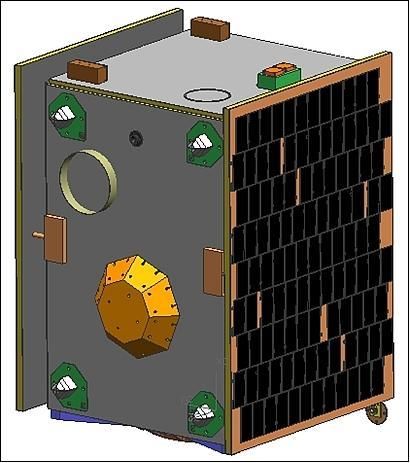
• Reaction wheels are used to change the spacecraft’s
attitude. Four reaction wheels are most commonly placed in
a tetrahedral configuration to provide 3-axis control even in
the event of one of the wheels failing. Details of this
CC BY-SA 4.0:
configuration are provided on the next slide.
31Reaction Wheel Configuration
The tetrahedral reaction wheel configuration is
Z preferred as in the event of a single wheel failure,
control over all 3-axis of the spacecraft is still possible
with the remaining wheels.
The tetrahedral configuration also enables the
generation of twice as much torque in each of the
body axis compared to a standard 3-wheel design.
The figure on the left is one possible tetrahedral
reaction wheel configuration. It is called the
Y tetrahedral configuration as the rotation axis of each
of the wheels point along one of the vertices of a
tetrahedron.
The x, y and z axis shown are the body-fixed axis of the
spacecraft. The angles describing the orientation of
these wheels can be used in your structure concepts.
X It is the direction of the spin axis of reaction wheels
Example Tetrahedral Reaction that is important, rather than their position within the
Wheel Configuration - Source spacecraft. They are however typically placed on a
single level, far from the centre of mass as this results
2021 2021
in a more favourable mass distribution.
Satellite
Satellite
4.0:4.0:
Open Source
Source
BY-SA
CC BY-SA
Open
32
CCLaunch Vehicle Fairings &
Integration
• A spacecraft must fit inside of the fairing envelope of
the launch vehicle that it is going to use.
• The OSSAT will need to fit inside of a wide range of
launch vehicle fairings. Launcher datasheets will be
provided with this slide deck. These documents can be
used to determine the maximum dimensions of the
structure concept.
• A satellite also requires a separation system which is
how it is attached to the launch vehicle. An example of
a separation system that should be used for the
Open Source Satellite 2021
structure concepts is given on slide 12
CC BY-SA 4.0:
33Centre of Mass Considerations
• The centre of mass has a number of implications on
the operation of the spacecraft.
• Launch vehicle providers will typically have a
requirement on the position of the centre of mass with
respect to the separation system.
• For this level of concept design, the centre of mass
should be as close to the centreline of the satellite as
possible. This centreline should be taken as running
along the centre of the satellite, through the centre of
the separation system.
Open Source Satellite 2021
• Thruster positioning with respect to the centre of mass
is also important. The propulsion system should be
designed such that the resultant thrust vector acts
CC BY-SA 4.0:
approximately through the centre of mass.
34Please feel free to contact
a member of our team if
you have any questions!
Good luck! We can’t wait to see what you come up with!
Open Source Satellite 2021
CC BY-SA 4.0:
35Get Involved:
www.opensourcesatellite.org/register
linkedin.com/company/open-source-satellite
@SatelliteOpen
info@opensourcesatellite.org
Open Source Satellite 2021
Building A2, Cody Technology Park,
Farnborough, GU14 OLX
CC BY-SA 4.0:CC BY-SA 4.0: Open Source Satellite 2021
You can also read