Kinetic Model Generation from Triangular Mesh Models - CAD Journal
←
→
Page content transcription
If your browser does not render page correctly, please read the page content below
1130

         Kinetic Model Generation from Triangular Mesh Models

                 Ji M. Park1   , Min S.Ko2   , Woong G.Lee3      and Sang C. Park4

                               1Ajou University, jmpark89@ajou.ac.kr
                                  2AjouUniversity, killay@ajou.ac.kr
                               3Ajou University, boilerno1@ajou.ac.kr
                                4Ajou University, scpark@ajou.ac.kr

                      Corresponding author: Sang C. Park, scpark@ajou.ac.kr

        Abstract. The virtual commissioning technology has been considered as a very
        effective tool to detect and correct errors generated during the design stage of a
        production system. To enjoy the benefits of virtual commissioning technology, it is
        essential to develop a more efficient methodology to construct virtual device
        models. A virtual device model consists of two sub-models, a geometric model and
        a kinetic model. This paper proposes a methodology to extract a kinetic model from
        the geometric model of a virtual device. The proposed approach consists of four
        steps; 1) find all cylindrical shapes from two links, 2) identify sliding surface areas
        from the set of cylindrical shapes, 3) identify the limiting surface areas by finding
        the adjacent triangles of the sliding surface areas, and 4) identify a joint between
        two given links. Among the four steps, the first step, finding cylindrical shapes from
        a solid model, is not a trivial problem when the design history information is not
        available. To solve the problem, we devise the concept of a T-Gauss map. By using
        the T-Gauss map, we can easily find cylindrical shapes by finding great circles on a
        T-Gauss map. The proposed procedure has been implemented and tested with
        various examples.

        Keywords: Virtual commissioning, Fixture modeling, Kinetic model, Geometric
        model, Gauss map
        DOI: https://doi.org/10.14733/cadaps.2020.1130-1142

1   INTRODUCTION
The modern manufacturing environment can be characterized by significant cost constraints,
global competition, shifting customer values, shortening of product life-cycles and rapid time-to-
market. To be successful in the fast changing manufacturing scenario, manufacturers must strive
to improve not only the quality of their products but also the efficiency of their production
systems. This demand has resulted in the concept of a virtual factory which is a model executing
virtual manufacturing processes within a computer simulation [1, 9, 16]. For the implementation of
a virtual factory, it is necessary to construct digital models for all the physical and logical elements

                                     Computer-Aided Design & Applications, 17(6), 2020, 1130-1142
                                           © 2020 CAD Solutions, LLC, http://www.cad-journal.net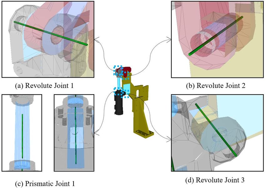
1131

(entities and activities) of a real manufacturing system [5, 7, 12, 13]. Once a virtual factory is
constructed, it is possible to evaluate the physical validity and efficiency of co-working machines,
as well as the production capability of the system. Figure 1 shows the concept of virtual
commissioning by making use of a virtual factory. The key idea of virtual commissioning is to
include real control devices (PLCs, PCs) of a production system in the simulation of a virtual
factory. One of the major benefits of virtual commissioning is the early detection and correction of
errors generated during the design stage of a production system. As a result, we can save a lot of
time and efforts for debugging and correction expended during real commissioning. An
experienced study in virtual commissioning [6] shows the positive effect of virtual commissioning
on the error rate during real commissioning. The results showed a reduction of real commissioning
time by 75%, resulting from enhanced quality of the manufacturing system at the start of real
commissioning.
     Although virtual commissioning may provide various benefits, it is not easy to enjoy the
benefits of the technology in reality. One of the major obstacles of the virtual commissioning is the
excessive time and efforts expended during the construction of virtual device models which require
high fidelity. A virtual factory consists of various virtual devices such as robots, conveyors,
fixtures, machining and assembly tools. Many of these devices need to contain both of a geometric
model and a kinetic model. Figure 2 shows an example of a fixture model. The virtual device model
(Figure 2-(c)) consists of a geometric model (Figure 2-(a)) and a kinetic model (Figure 2-(b)).
Once a virtual device model is properly constructed, it is possible to do the motion planning (Figure
2-(d)) which is very essential for the virtual commissioning.

                          Figure 1: The concept of virtual commissioning.

                                    Computer-Aided Design & Applications, 17(6), 2020, 1130-1142
                                          © 2020 CAD Solutions, LLC, http://www.cad-journal.net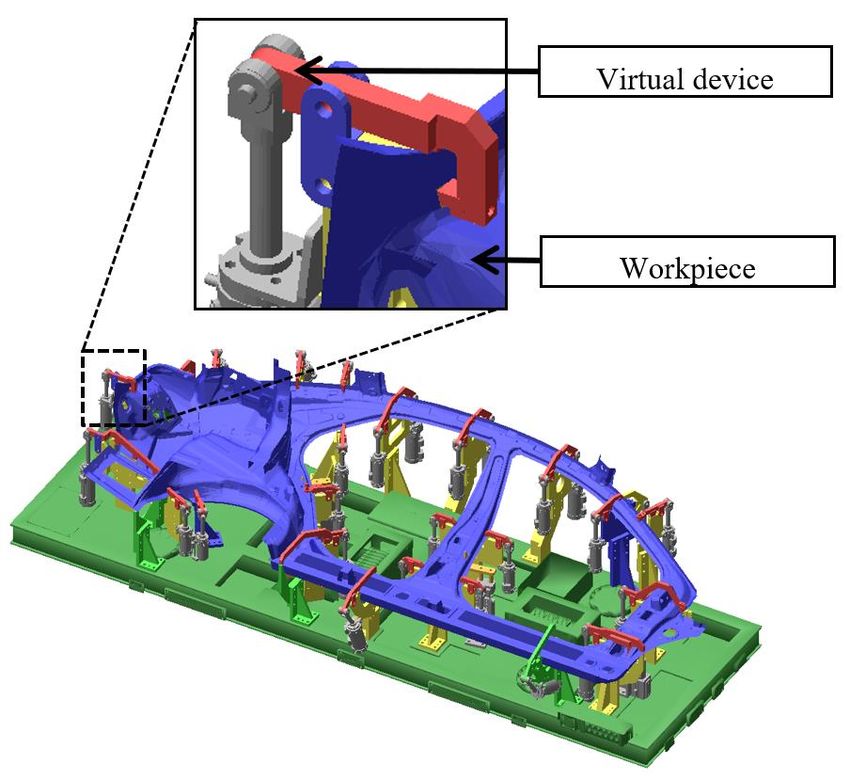
1132

Figure 2: Virtual device consisting of a geometric model and a kinetic model.

  Figure 3: Geometry modeling of a virtual device for a given workpiece.

                        Computer-Aided Design & Applications, 17(6), 2020, 1130-1142
                              © 2020 CAD Solutions, LLC, http://www.cad-journal.net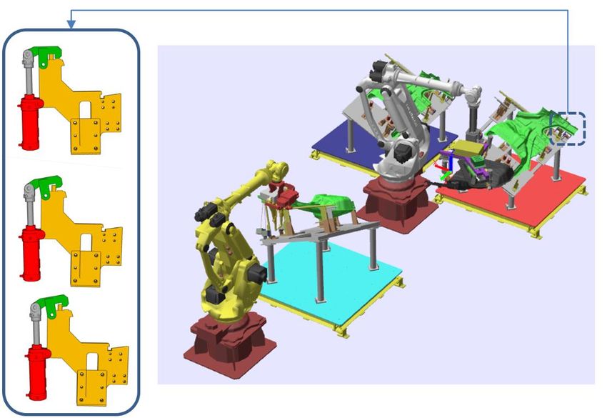
1133

As shown in Figure 3, the geometric model of a virtual device should be designed for a given
workpiece with 3-dimensional CAD data [11, 14]. Since manufacturing devices should locate, hold
and support a workpiece during manufacturing process, the geometry of a virtual device contacting
with a workpiece should be designed very carefully, as shown in Figure 3. For the geometric
modeling of virtual device, there have been many previous research results. Asada and By used the
Jacobian Matrix to model the device-workpiece relationship in 3D space [2]. Trappey et al.
discussed the time-variant stability problem with consideration of fixture force limits and directions
[15]. Later, Kang, Rong et al. proposed a framework for the modeling of a virtual device [8]. Two
sub-models, geometric and kinetic, are established in the proposed framework. They are applied to
three areas of fixture applications including locator analysis, tolerance analysis, and stability
analysis. Recently, Mervyn, Kumar et al. developed an evolutionary search algorithm exploring the
large number of possible alternatives and suggesting an appropriate geometric design of a virtual
device [20]. Although most of previous research deals with the geometric modeling of a virtual
device, Chang, Ko et al. proposed a procedure for the kinetic modeling of the slider-crank
mechanism, a four-axis system with three revolute and one prismatic axis [3]. They used the
concept of ‘moment of inertia’, which is a measure of an object’s resistance to changes in its
rotation rate, to identify the kinetic model of the slider-crank mechanism. Although their algorithm
works efficiently, it cannot apply to general devices other than the slider-crank mechanism.
     To enjoy the benefits of virtual commissioning technology, it is essential to develop a more
efficient methodology to construct virtual device models. As depicted earlier, a virtual device
model consists of two sub-models, a geometric model and a kinetic model. While the geometric
modeling of a virtual device has been given a great deal of attention, the kinetic modeling of a
virtual device has rarely been brought into focus. Currently, the kinetic modeling of a virtual device
is performed manually, and it takes much time and effort.

                  Figure 4: Industrial devices with revolute and prismatic joints.

                                    Computer-Aided Design & Applications, 17(6), 2020, 1130-1142
                                          © 2020 CAD Solutions, LLC, http://www.cad-journal.net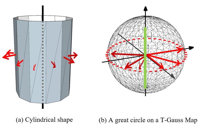
1134

    To cope with the problem, this paper proposes a procedure for the efficient construction of the
kinetic model of a virtual device. The proposed procedure only focuses on general industrial
devices (Figure 4) consisting of revolute and prismatic joints without any complicated joints which
can be found in special purpose machines. The remainder of this paper is organized as follows.
Section 2 presents the overall approach to the construction of a kinetic model from a given
geometric model. Section 3 explains the details of the proposed algorithm. Section 4 presents
concluding remarks.

2   APPROACH TO CONSTRUCT A KINETIC MODEL
Our objective is to develop an efficient procedure to construct a kinetic model for a virtual device.
The input of the procedure is the geometric model of a virtual device which consists of multiple
components (links). Each link of a virtual device is represented by a solid model (a triangular
mesh). Two adjacent links are connected through a joint. Most of virtual devices can be
represented by using two types of joints; 1) a revolute joint describing single-axis rotational
movements between two links, and 2) a prismatic joint providing a liner sliding movement between
two links. Formal definitions of the two joints are as follows:
    •   A revolute joint requires a line (axis of the joint) in the moving body (link) to remain co-
        linear with a line in the fixed body, and a plane “perpendicular” to this line in the moving
        body maintain contact with a similar “perpendicular” plane in the fixed body.
    •   A prismatic joint requires that a line (axis of the joint) in the moving body (link) remain co-
        linear with a line in the fixed body, and a plane “parallel” to this line in the moving body
        maintain contact with a similar “parallel” plane in the fixed body.

Both of joints impose five constraints on the relative movement of the links, which therefore has
one degree of freedom. To define a joint, we need to find the axis as well as the type (prismatic or
revolute). As shown in Figure 5, the proposed procedure extracts the kinetic model (set of joints)
from the given geometric model of a virtual device.

                          Figure 5: A revolute joint and a prismatic joint.

                                    Computer-Aided Design & Applications, 17(6), 2020, 1130-1142
                                          © 2020 CAD Solutions, LLC, http://www.cad-journal.net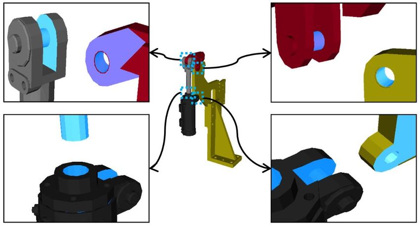
1135

When two links touch, a certain portion of their surface areas will be in contact each other. Since a
joint may exist between two connected links, it is necessary to find the ‘contact surface areas (CA)’
between them to identify the joint. Friction is the force that resists motion when the surface of one
object comes into contact with the surface of another. Since, friction reduces the mechanical
advantage or the ratio of output to input, it is desirable to minimize the force due to friction.
Without loss of generality, we can assume that the contact surface areas between two links include
cylindrical shapes which minimize the force due to friction. As shown in Figure 6, we can extract
the cylindrical areas from contact surface areas, and call them ‘sliding surface areas (SA)’. In the
case of non-cylindrical surface areas of contact surface areas are referred to as ‘limiting surface
areas (LA)’. In other words, contact surface areas consists of sliding surface areas and limiting
surface areas (CA = SA + LA).
     Without the limiting surface areas of the contact areas, it is not possible to differentiate the
revolute joint from the prismatic joint. While the limiting surface areas of a prismatic joint allow
the linear movement along the joint axis (Figure 7), those of a revolute joint do not allow any
linear movements along the joint axis (Figure 6). Once the sliding surface areas and limiting
surface areas are identified, the joint type can be determined by checking the possibility of linear
movements along the joint axis. To do so, it is necessary to have an efficient algorithm to find the
limiting surface areas and sliding surface areas between two links. The algorithm will be explained
in the next section.

                        Figure 6: Contact surface areas of a revolute joint.

3   ALGORITHM TO FIND SLIDING PART & LIMITING PART
As mentioned earlier, the identification of sliding surface areas and limiting surface areas between
two links is very important for the extraction of a kinetic model from a given geometric model. To
do so, we may think of a trivial approach; 1) compute the contact surface areas between two links
(solid models), and 2) extract the sliding & limiting surface areas from the contact surface areas.
Although this method looks quite simple, it has two major problems; 1) the computation of contact

                                    Computer-Aided Design & Applications, 17(6), 2020, 1130-1142
                                          © 2020 CAD Solutions, LLC, http://www.cad-journal.net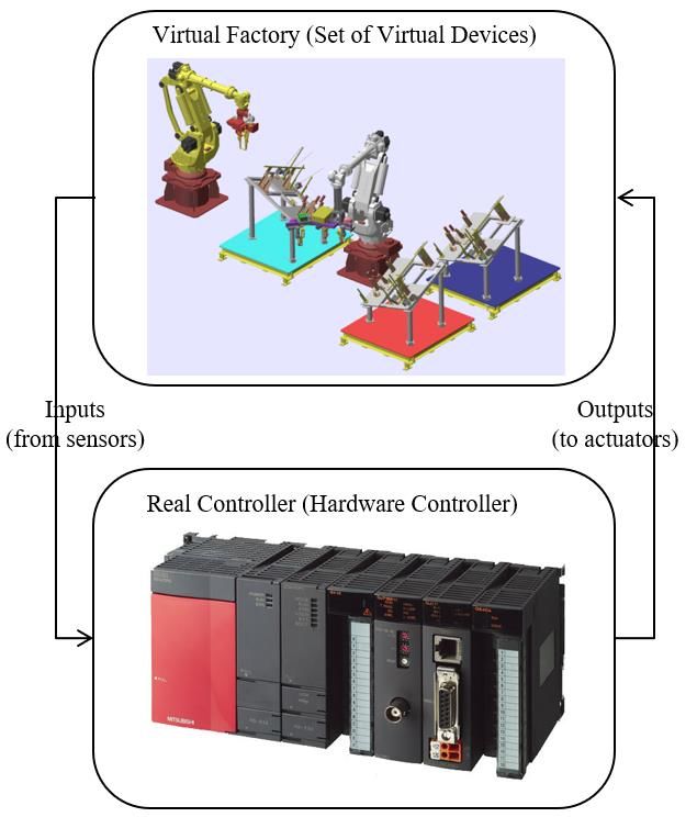
1136

surface areas between two solid models is an expensive operation especially for complicated
models [13], and 2) the extraction of the sliding & limiting surface areas from the contact surface
areas is not a trivial problem.

                        Figure 7: Contact surface areas of a prismatic joint.

To cope with the problems, we make use of the inherent attributes of the given geometric model
consisting of multiple links. Each link is a solid model and represented in the form of a triangular
mesh. As mentioned earlier, the sliding surface areas between two links are cylindrical shapes to
minimize the force due to friction. Considering the attribute, we can narrow the range of interest
to the cylindrical surface areas of two given solid models (links). Once the two groups of cylindrical
surface areas are identified from two links, we can intuitively identify the sliding surface areas
from the contact of the two groups of cylindrical surface areas. At this time, the computation
becomes very efficient, because we only focus on cylindrical areas. Now the problem is how to find
cylindrical areas from a given solid model.
    To find cylindrical areas from a given solid model, we introduce the concept of ‘Gauss map’
[4]. In differential geometry, the ‘Gauss map’ maps a surface in Euclidean space to the unit
sphere. Based on the Gauss map, we propose a new data concept called a ‘T-Gauss map’. The T-
Gauss map is devised for the effective identification of cylindrical surface areas from a triangular
mesh. For a triangular mesh, a Gauss map can be defined as a unit sphere with intersection points
of the normal vectors of all triangles and the unit sphere, as shown in Figure 8-(a). While a Gauss

                                    Computer-Aided Design & Applications, 17(6), 2020, 1130-1142
                                          © 2020 CAD Solutions, LLC, http://www.cad-journal.net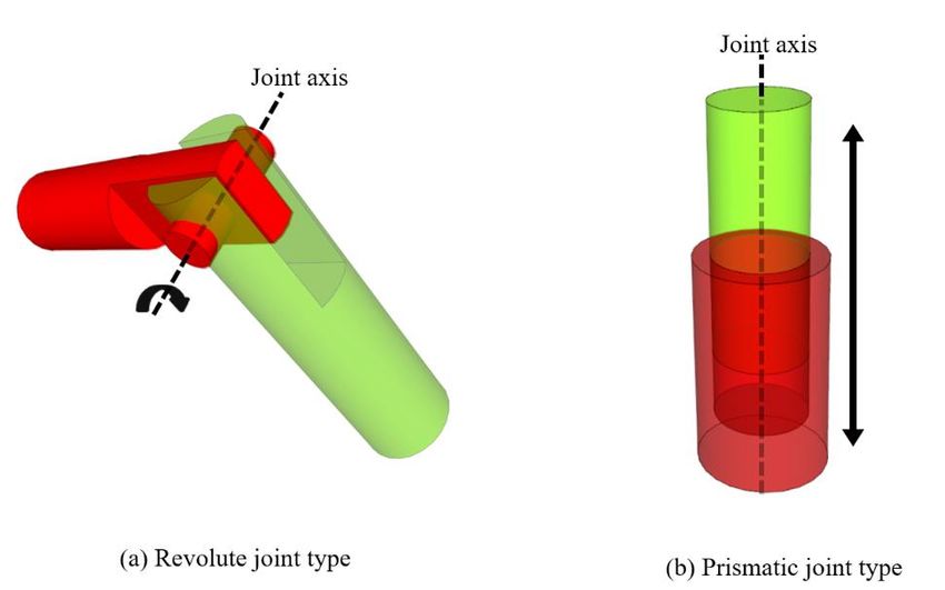
1137

map shows only the intersections points, the T-Gauss map additionally represents the topology
information of a given triangular mesh. Figure 8-(b) shows a T-Gauss map for a given triangular
mesh consisting of three triangles T1, T2 and T3. Since two pairs of triangles (T1 & T2, T2& T3) are
adjacent (sharing the same edge), the T-Gauss map includes two arcs on the unit sphere
representing the topology information of the given triangular mesh. Considering this attribute of a
T-Gauss map, we can easily identify cylindrical shapes from a solid model, because a cylindrical
shape makes a great circle on a T-Gauss map, as shown in Figure 9.
    The proposed approach consists of four steps; 1) find all cylindrical shapes from two links, 2)
identify sliding surface areas from the set of cylindrical shapes, 3) identify the limiting surface
areas by finding the adjacent triangles of the sliding surface areas, and 4) identify a joint between
two given links. Among the four steps, the first step, finding cylindrical shapes from a solid model,
is not a trivial problem when the design history information is not available. To solve the problem,
we devise the concept of a T-Gauss map. By using the T-Gauss map, we can easily find cylindrical
shapes by finding great circles on a T-Gauss map. The problem of identifying the joint between
two links can be described as follows:
    Joint_Identification_between_Two_Links
    •   Input: Two links (solid models) L1, L2
    •   Output: Joint_axis, Joint_type (revolute or prismatic)
    •   Variables:
        S1, S2, S3: set of cylinders, Gmap1, Gmap2: T-Gauss maps
        1) Gmap1 = Construct a T-Gauss map with L1;
        2) Gmap2 = Construct a T-Gauss map with L2;
        3) S1 = find all cylinders by identifying the great circles of Gmap1   ;
        4) S2 = find all cylinders by identifying the great circles of Gmap2   ;
        5) For (every cylinder ci of S1) {
                 a1 = axis of ci ;
                 For (every cylinder cj of S2) {
                         If (a1 == axis of cj) {
                                   Joint_axis = a1 ;
                                   Go to Step 7;
                         }
                 }
            }
        6) Return joint_axis & joint_type (NULL); // no joint
        7) S3 = extract cylinders having the same axis with the joint_axis     from S1 & S2;
        8) Limiting_part = Find all adjacent faces of S3;
        9) If (Limiting_part constrains a linear movement along                    with   the   joint_axis)
                 joint_type = revolute ; Else joint_type = prismatic ;
        10) Return joint_axis & joint_type ;

As mentioned earlier, the objective of this paper is to extract a kinetic model from the geometric
model of a virtual device. A kinetic model is a set of joints, and a joint has an axis and its type
(prismatic or revolute). By using the joint identification algorithm, we can describe the full
procedure as follows:

     Kinetic model extraction algorithm from a geometric model
    •   Input: A virtual device consisting of multiple links, L1, L2, … , Lk
    •   Output: KM (a kinetic model), a set of joints
    •   Variables:
        J: a joint, La & Lb: links
      1) KM = {};
      2) For (int i= 1; i < k ; i++) {

                                     Computer-Aided Design & Applications, 17(6), 2020, 1130-1142
                                           © 2020 CAD Solutions, LLC, http://www.cad-journal.net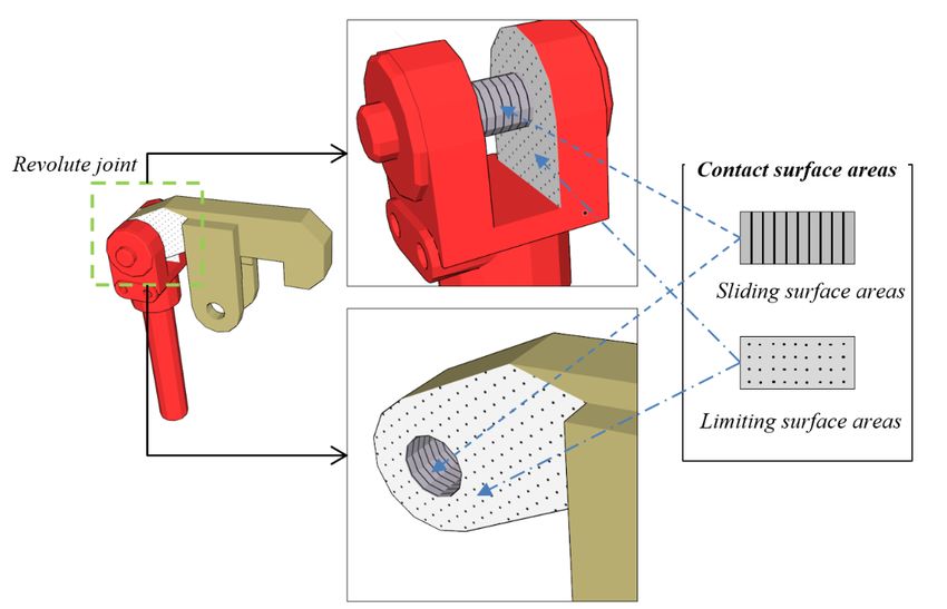
1138

             For (int j = i+1 ; j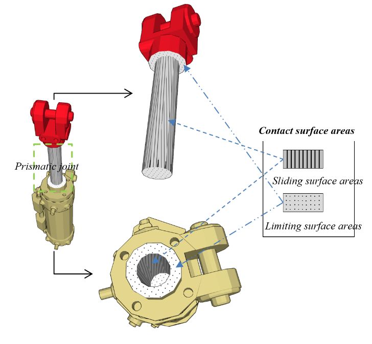
1139
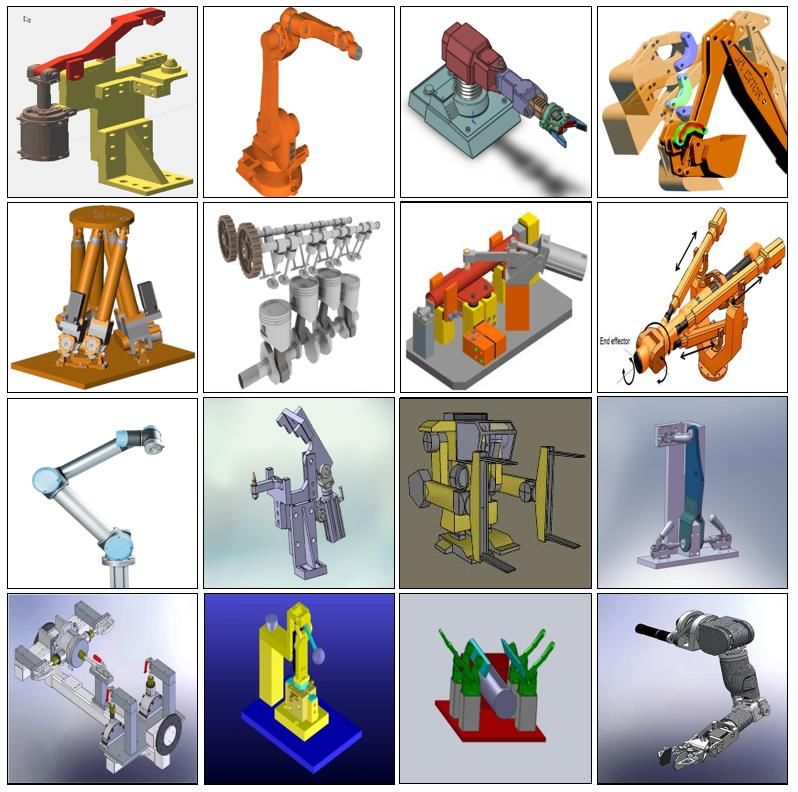
for given links. As shown in Figure 10, it is possible to identify the sliding surface areas and the
limiting surface areas by making use of the found cylindrical shapes. Once the sliding surface areas
and the limiting surface areas are identified, we can determine the joint axis & type, as shown in
Figure 11.
Figure 10: Identification of contact surface areas for a given virtual device consisting of four links.
Figure 11: Identification of three revolute joints and one prismatic joint.
Computer-Aided Design & Applications, 17(6), 2020, 1130-1142
© 2020 CAD Solutions, LLC, http://www.cad-journal.net1140
The work-holding device in a robotic cell is a fixture, and it is very important to design & verify the
geometry of fixtures, as well as the motion of fixtures. Figure 12 shows a robotic cell consisting of
two robots and three fixtures holding automotive components. Once the fixture motions are
defined, it is necessary to check if the motions cause any unintended interference or collisions.
After verification, the fixture designs go to downstream applications including the off-line
programming of robots, and the manufacturing of fixtures.
Figure 12: Motion simulation & the virtual commissioning of a robotic cell.
4 CONCLUSIONS
The virtual commissioning includes real controllers in the simulation of a virtual factory, a digital
model imitating the physical and logical aspects of a real manufacturing system. A virtual factory
consists of multiple virtual devices, and a virtual device model consists of two sub-models, a
geometric model and a kinetic model. This paper proposes a methodology to extract a kinetic
model from the geometric model of a virtual device.
The input of the proposed procedure is the geometric model of a virtual device which consists
of multiple components (links). Each link of a virtual device is represented by a solid model (a
triangular mesh). Two adjacent links are connected through a joint. Most of virtual devices can be
represented by using two types of joints; 1) a revolute joint describing single-axis rotational
movements between two links, and 2) a prismatic joint providing a liner sliding movement
between two links. The proposed approach, extracting a kinetic model from the geometric model of
a virtual device, consists of four steps. Among the four steps, the first step, finding cylindrical
shapes from a solid model, is not a trivial problem when the design history information is not
Computer-Aided Design & Applications, 17(6), 2020, 1130-1142
© 2020 CAD Solutions, LLC, http://www.cad-journal.net1141
available. To solve the problem, we devise the concept of a T-Gauss map. By using the T-Gauss
map, we can easily find cylindrical shapes by finding great circles on a T-Gauss map. we verified
the generation of a kinematic model with the work-holding device in a robotic cell.
Although the main application of the proposed approach is an automated production system,
it can be applied to any other industries requiring the virtual commissioning. In the future, we will
apply the results of this study to motion simulations to verify that the mission can be satisfied at
the design stage of the aircraft and ship.
Ji M. Park, https://orcid.org/0000-0002-0629-6987
Min S. Ko, https://orcid.org/0000-0001-7088-3150
Woong G. Lee, https://orcid.org/0000-0002-3117-7429
Sang C. Park, https://orcid.org/0000-0002-7832-2742
ACKNOWLEDGEMENTS
This work was supported by the technology innovation program (20002772, Development of the
smart manufacturing collaboration system for the innovation of pipe and steel outfit and block
logistics in the shipbuilding and marine) funded by the Ministry of Trade, Industry & Energy
(MOTIE, Korea). Also, the research was supported by the Defense Acquisition Program
Administration and the Agency for Defense Development (UD180018AD).
REFERENCES
[1] Anglani, A.; Grieco, A.; Pacella, M.; Tolio, T.: Object-oriented modeling and simulation of
flexible manufacturing system: a rule-based procedure, Simulation Modeling Practice and
Theory, 10, 2002, 209-234. https://doi.org/10.1016/S1569-190X(02)00100-4
[2] Asada, H.; By, A.: Kinematic analysis of workpart fixturing for flexible assembly with
automatically reconfigurable fixtures, IEEE Journal on Robotics and Automation, 1985, 86-94.
https://doi.org/10.1109/JRA.1985.1087007
[3] Chang, M. H.; Ko, M. S.; Park, S. C.: Fixture modelling for an automotive assembly line,
International Journal of Production Research, 49(15), 2011, 4593-4604.
https://doi.org/10.1080/00207543.2010.506893
[4] Chen, L. L.; Woo, T. C.: Computational geometry on the sphere with application to
automated machining, Journal of Mechanical Design, 114, 1992, 288-295.
https://doi.org/10.1115/1.2916945
[5] Choi, B. K.; Kim, B. H.: New trends in CIM: Virtual manufacturing systems for next
generation manufacturing, Current Advances in Mechanical Design and Production Seventh
Cairo University International MDP Conference, Cairo, February 15-17, 2000, 425-436.
[6] Hoffman, P.; Maksoud, T. M. A.; Schuman, R.; Premier, G. C.: Virtual commissioning of
manufacturing systems a review and new approaches for simplification, Proceedings 24th
European Conference on Modeling and Simulation, 2010, 407–412.
https://doi.org/10.7148/2010-0175-0181
[7] Iwata, K.; Onosato, M.; Teramoto, K.; Osaki, S.: A modeling and simulation architecture for
virtual manufacturing systems, CIRP Annals, 44(1), 1995, 399-402.
https://doi.org/10.1016/S0007-8506(07)62350-6
[8] Kang, Y.; Rong, Y.; Yang, J. A.: Geometric and kinetic model based computer-aided fixture
design verification, Journal of Computing and Information Science in Engineering, 3, 2003,
187-199. https://doi.org/10.1115/1.1607352
[9] Klingstam, P.; Gullander, P.: Overview of simulation tools for computer-aided production
engineering, Computers in Industry, 38, 1999, 173-186. https://doi.org/10.1016/S0166-
3615(98)00117-1
Computer-Aided Design & Applications, 17(6), 2020, 1130-1142
© 2020 CAD Solutions, LLC, http://www.cad-journal.net1142
[10] Mervyn, F.; Kumar, A. S.; Nee, A. Y. C.: Automated synthesis of modular fixture design using
and evolutionary search algorithm, International Journal of Production Research, 43(23),
2005, 5047-5070. https://doi.org/10.1080/00207540500160904
[11] Mervyn, F.; Kumar, A.S.; Nee, A.Y.C.: Fixture design information support for integrated
design and manufacturing, International Journal of Production Research, 44(11), 2006, 2205-
2219. https://doi.org/10.1080/00207540500465303
[12] Onosato, M.; Iwata, K.: Development of a virtual manufacturing system by integrating
product models and factory models, CIRP Annals, 42(1), 1993, 475-478.
https://doi.org/10.1016/S0007-8506(07)62489-5
[13] Park, S. C.; Chang, M. H.: An algorithm to extract machining volumes, The International
Journal of Advanced Manufacturing Technology, 36(9-10), 2008, 942-949.
[14] Pehlivan, S.; Summers, J. D.: A review of computer-aided fixture design with respect to
information support requirements, International Journal of Production Research, 46(4), 2008,
929-947. https://doi.org/10.1080/00207540600865386
[15] Trappey, A. J. C.; Liu, C. R.: Automatic workholding verification system, Robotics and
Computer-Integrated Manufacturing, 9(4), 1992, 321-326.
[16] Ye, L.; Lin, F.: Virtual system simulation – A step beyond the conventional simulation,
Proceeding of the 22nd International Conference on Computer and Industrial Engineering,
1997, 304-306.
Computer-Aided Design & Applications, 17(6), 2020, 1130-1142
© 2020 CAD Solutions, LLC, http://www.cad-journal.netYou can also read