Measuring Pleated Knitted Sensors - Proceedings - MDPI
←
→
Page content transcription
If your browser does not render page correctly, please read the page content below
Proceedings

Measuring Pleated Knitted Sensors †
Giorgia Petri * and Berit Greinke

 College of Architecture, Media and Design, Berlin University of the Arts, 10587 Berlin, Germany;
 b.greinke@udk-berlin.de
 * Correspondence: g.petri@udk-berlin.de
 † Presented at the International Conference on the Challenges, Opportunities, Innovations and Applications
 in Electronic Textiles (E-Textiles 2020), Virtual venue, UK, 4 November 2020.

 Abstract: This paper presents preliminary results from a study of pleated electronic textile (e-textile)
 sensors, focusing on prototyping and measuring electrical resistance of three knitted sensors. This
 work is part of a larger research project, investigating the interaction between body and e-textiles
 with a three-dimensional structure for creative performance applications. First, electrical properties
 of the pleated textile sensors were determined. Sensors were measured in a purpose-built low-cost
 recording device, which was set up to record electrical resistance, taken from the fabric while it was
 folded and unfolded. Different modes of connecting the samples to the microcontroller were also
 tested. Each sensor was tested three times with three different stretch lengths. The results show that
 one of the most significant factors to use knitted pleats as an input is the combination of yarns com-
 bined with the tension of the knitting machine.

 Keywords: pleated e-textiles; sensor properties; knitting

 1. Introduction
 This project focuses on the interconnection between fashion, art, and technology. As
 an inspiration for the conceptual and technical development of pleated sensor structures,
Citation: Petri, G.; Greinke, B.
 an investigation was carried out into concepts of fold, language, body, and performance.
Measuring Pleated Knitted Sensors.
 As a foundation for the early concepts of the study, the relation between the body
Proceedings 2021, 68, 10. https://doi.
 and the fold of the fabric was explored through the notion of folds defined by Deleuze [1].
org/10.3390/proceedings2021068010
 Clothing for Deleuze is no longer subjugated by the body, but becomes an autonomous
 independent entity, which through its folds interacts with the body, complementing and
Published: 13 January 2021
 enriching it, instead of just covering it [2]. For that reason, this research focuses on the
Publisher’s Note: MDPI stays neu-
 creation of autonomous three-dimensional shapes and volumes through the use of folds.
tral with regard to jurisdictional Different textile pleating techniques were examined with respect to aesthetics, per-
claims in published maps and insti- formance, and interaction potential of pleated textile interfaces. Despite advances in the
tutional affiliations. field of e-textiles, problems are still encountered with the controllability and stability of
 the textile sensors [3].
 Textile sensors, especially pressure and stretch sensors, have been used for a number
 of years, in particular for health monitoring. Used as breath sensors embedded in gar-
Copyright: © 2021 by the authors.
 ments [4] or pressure sensors embedded in socks [5], sensors are often knitted or woven.
Licensee MDPI, Basel, Switzerland.
 In this research, an industrial mechanical knitting machine was used to produce the first
This article is an open access article
 samples. Unlike weaving, which links multiple yarns in a cross-section, knitting creates a
distributed under the terms and con-
 three-dimensional structure using a single yarn. The varying of the number and the posi-
ditions of the Creative Commons At-
 tion of the needles in the respective knitting machine, or the stitches during the knitting
tribution (CC BY) license (http://cre-
ativecommons.org/licenses/by/4.0/).
 process, allows for more variety of design and less waste of material.

Proceedings 2021, 68, 10; doi:10.3390/proceedings2021068010 www.mdpi.com/journal/proceedings
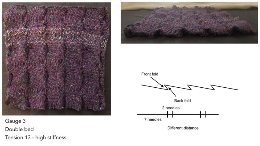
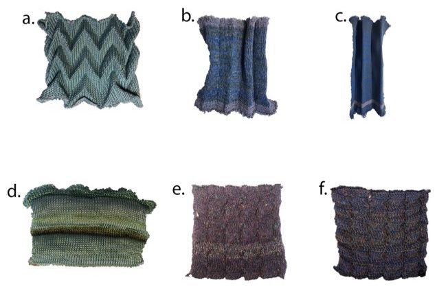
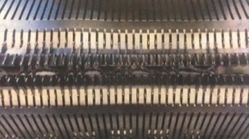
Proceedings 2021, 68, 10 2 of 7

 2. Material and Knitting Techniques
 In the first part of the study, pleated fabrics were developed using a manual, double-
 bed knitting machine. The intention was to study possibilities to incorporate three-dimen-
 sional electronic elements already during the fabric construction process. A first series of
 samples was used to study the stiffness necessary for the pleat to be used as an input
 device. Different knitting techniques were tested for the sampling of textile sensors. Vari-
 ous conductive and supporting threads and yarns were used for binary switches and
 stretch sensor designs [3]. Two basic approaches were adopted in this step. One was to
 knit the sample flat and then fold it using paper molds and steam (Figure 1a). The other
 was to create the three-dimensional shape with the conductive material embedded during
 the knitting process (Figure 1b–f). Regarding the pleating technique during the knitting
 process, the following two-fold shapes were made: straight lines and zigzag lines. For the
 straight lines, two needles between four knitting needles in the front bed were deactivated
 and their stitches were hung on the back bed. The two needles in the back bed, on the
 right side next to the needles with the hung-on stitches from the front bed, were also
 turned off and their stitches were hung to the front bed (Figure 2). The knitting process
 was continued (Figure 1b,c). As for the zigzag lines, two needles between seven knitting
 needles in the front bed were deactivated and their stitches were hung on the back bed.
 The same process was followed for the back bed as for the straight lines. The difference
 was that, during the knitting process, the back bed was moved in one direction and it
 stayed in the new position for two rows of knitting. After four rows of knitting, the same
 process was followed in the other direction (Figure 1e,f).

 Figure 1. Study on pleats and stiffness: (a) Knitted sample, pleated with steam; (b) Knitted pleated
 sample, no stiffness; (c) knitted pleated sample, medium stiffness; (d) knitted sample, pressure
 sensor with conductive wool inside; (e) knitted pleated sample, good stiffness; (f) knitted pleated
 sample, good stiffness.

 Figure 2. Knitting machine setup to pleat.

 It was found that the use of an industrial manual knitting machine with gauge 3 and
 a wool yarn mixed with elastic yarn and Schoeller 100% Inox NM 22/2 yarn (Figure 3) led
 to the best outcomes. These make the fabric sufficiently stiff to keep the structure folded
 and deliver robust data input. In some cases, the conductive thread broke during the knit-
 ting process when the tension was changed.
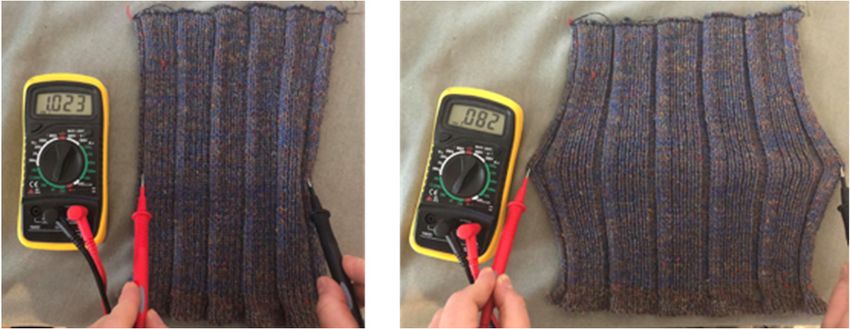
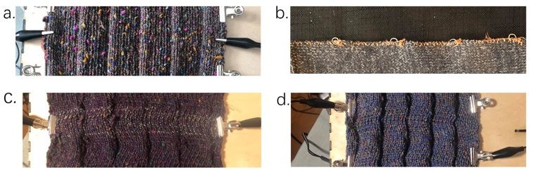
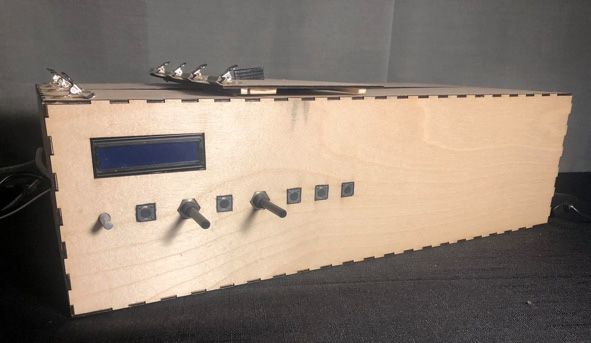
Proceedings 2021, 68, 10 3 of 7

 Figure 3. Schoeller 100% Inox NM 22/2.

 3. Measurement Setup
 A measurement setup was designed and built for recording electrical resistance dur-
 ing the stretching and releasing of the structure (Figure 4). Sequences of stretching and
 releasing can be programmed by setting speed, starting position, and length of movement.
 The sensors were measured in cycles of six motions, with three different distances. To
 record the values coming from the sensor, an Arduino Uno microcontroller (arduino.cc)
 was used combined with the softwares Arduino IDE (v. 1.8.10) and Max 8 (v. 8.0.6; Cycling
 ’74, San Francisco, CA, USA). Different modes of connecting the samples to the microcon-
 troller were also tested (Figure 5). The highest stability was achieved using metal clip con-
 nectors on the same line (Figure 5c), and when a larger surface for connection was added
 using conductive thread (Figure 5b). Where it was possible and the width of the sensitive area
 allowed it, a test was made with crocodiles placed on clips at different heights (Figure 5d).

 Figure 4. Testing machine: it makes a linear movement to stretch and release the sample. It is pos-
 sible to set the starting position, the speed and the length of the movement.

 Figure 5. Connections: Leads with (a) crocodile clips, (b) stitches, (c) clips, (d) clips at different
 heights.

 A voltage divider circuit was built (Figure 6) to record the change in the resistance of
 the sensor connected to an analog pin of the microcontroller. The reference resistance was
 determined in advance testing the samples with the multimeter (Figure 7).
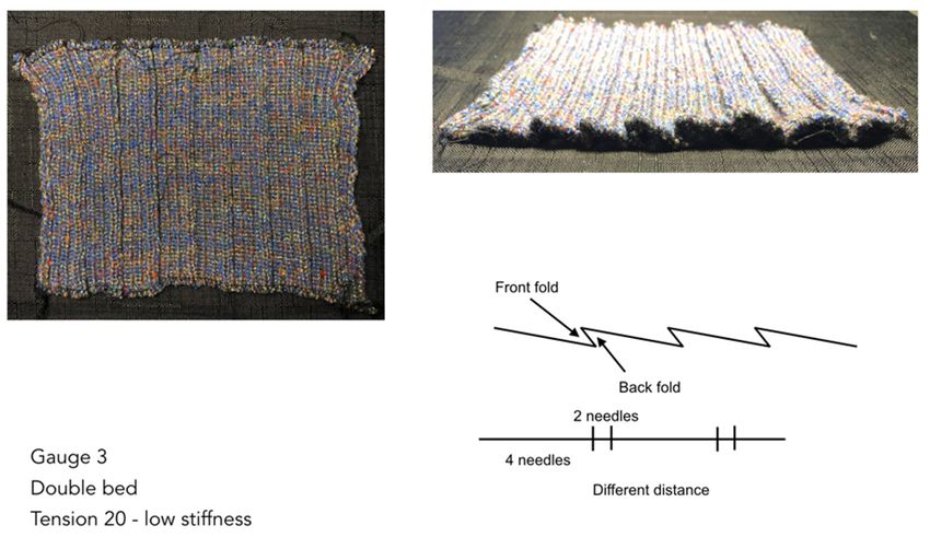
Proceedings 2021, 68, 10 4 of 7

 Figure 6. Voltage divider circuit.

 Figure 7. Testing resistance with the multimeter.

 Since Arduino’s analog pins read voltage and not the resistance over the two points,
 the output value needs to be converted. The real output voltage is calculated using the
 following equation:
 5

 1023
 The output voltage is converted to the sensor resistance using Ohm’s Law. After the
 conversion, the values are sent to a Max 8 patch for instant visual feedback and saving the
 data.

 4. Results
 Figures 8–10 show the samples selected for this measurement.

 Figure 8. Sample 1. Medium stiffness.
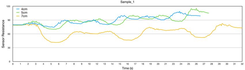
Proceedings 2021, 68, 10 5 of 7

 Figure 9. Sample 2. Low stiffness.

 Figure 10. Sample 3. High stiffness.

 All samples were made with a manual knitting machine with gauge 3 and double-
 bed functionality. The first sensor was set up with the machine tension set to 15. The textile
 sample was made with one elastic yarn, one thicker wool yarn, and Schoeller 100% Inox
 NM 22/2 yarn. A knife fold was used and with the distance of two needles between the
 fold on the front bed and the fold on the back bed. This combination of materials and
 structure resulted in good rigidity. The second sensor was set up with the tension set to
 20. The textile sample was made with the same yarns as the first one, but due to the dif-
 ferent tension this sensor was softer and less stiff. The distance between the folds in the
 two beds was the same as that of the first sample. The third sensor was set up with the
 tension of the machine set to 13. The textile sample was made with two yarns, i.e., one
 wool yarn and the Schoeller yarn. In this sample, the folds were not straight but followed
 a zigzag path. This sample was the stiffest of the three. The main weakness with this com-
 bination of materials, tension, and structure is that the conductive thread often broke, ei-
 ther during the knitting process or the measurements. Each sensor was measured three
 times with three different stretch lengths, to observe the sensor response and to test the chosen
 textile technique. The results show that the three sensors behave differently. Figures 11–13
 show electrical resistance (R) over the length of the elongation. The first sample demon-
 strates the most reliable performance in regard to the chosen textile technique. After the
 measurement, the sample has the same dimensions and all conductive threads are intact.
 What stands out in this sample (Figure 11) is the good behavior in terms of fatigue. We
 attribute this to the threads in combination with the setup of the machine. The initial R
 value is always similar after each testing cycle. The second sample differs from the first in
 the behavior after each testing cycle. In Figure 12, it can be seen that the resistance value
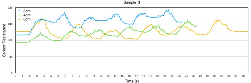
Proceedings 2021, 68, 10 6 of 7

 is always different. The value is shifting from 250 Ω to 450 Ω. Furthermore, it can be ob-
 served that, with the shorter movement of 4 cm, there has been just a small change in R so
 this combination of yarns and setting of the machine cannot detect small movements of
 the folds. The third sensor has a reasonably good response in terms of fatigue, with the
 resistance shifting from 186 Ω to 200 Ω. The chosen textile technique however was under-
 performing as the conductive thread often broke. Finally, using this technique and mate-
 rials, after even a single test cycle, the size of the sample changed as it stretched in the
 direction of the tested movement.

 Figure 11. Results of sample 1.

 Figure 12. Results of sample 2.

 Figure 13. Results of sample 3.

 5. Conclusions
 This paper presents the results of pleated knitted samples measurements. The find-
 ing shows that the tension of the machine is a key aspect to consider when designing
 pleated sensors so that the pleat is the input element.
 Further work is needed to improve the measurement setup, e.g., to eliminate noise
 and improve connections.

 Institutional Review Board Statement: Not applicable.
 Informed Consent Statement: Not applicable.
 Data Availability Statement: The data presented in this study are provided by the corresponding
 author upon request.
Proceedings 2021, 68, 10 7 of 7

References
1. Deleuze, G. The Fold, 3rd ed.; The Athlone Press: London, UK, 1993.
2. Smelik, A. Gilles Deleuze: Bodies-without Organs in the Folds of Fashion. In Thinking Through Fashion; Rocamora, A., Smelik,
 A., Eds.; Bloomsbury Publishing: London, UK, 2018; pp. 165–183.
3. Liang, A.; Stewart, R.; Bryan-Kinns, N. Analysis of sensitivity, linearity, hysteresis, responsiveness, and fatigue of textile knit
 stretch sensors. Sensors (Switzerland) 2019, 19, 3618.
4. Qureshi, W.; Guo, L.; Peterson, J.; Berglin, L.; Skrifvars, M. Knitted Wearable Stretch Sensor for Breathing Monitoring
 Application. In Proceedings of the Ambience’11, Borås, Sweden, 28–30 November 2011.
5. Qiu, P.Z. Importance of Home-Based, Self-Monitoring Devices and the Role of Pressure-Sensing Socks in Diabetic Foot Ulceration
 Prevention; Preliminary Report; Department of Design Engineering, Imperial College London: London, UK, 2020.
You can also read