Design and Control of an Air-Jet Lump Display
←
→
Page content transcription
If your browser does not render page correctly, please read the page content below
Design and Control of an Air-Jet Lump Display
James C. Gwilliam* Alperen Degirmenci∗ Matteo Bianchi† Allison M. Okamura‡
A BSTRACT
A common surgical task is identifying hard lumps embedded in
soft tissue. During open procedures, surgeons can localize lumps
using the distributed tactile feedback provided through manual pal-
pation with the fingers. Tactile displays developed to restore tactile
feedback for both traditional and robot-assisted minimally invasive
surgery (RMIS) are designed generically to provide a wide range
of tactile sensations to the finger, and as such, are often bulky and
electro-mechanically complex. We developed a novel adjustable
aperture air-jet pneumatic lump display that directs a thin stream
of pressurized air through an aperture onto the fingerpad. The dis-
play is designed to produce the sensation of a lump to the finger,
with minimal hardware requirements. It has two degrees of free-
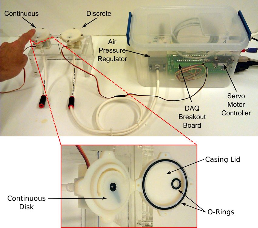
dom, enabling independent control of pressure and aperture size. (a) Air-Jet Lump Display (b) Control Parameters
We describe the design of the display and demonstrate the process
through which the output of the display can be controlled, using Figure 1: Pneumatic air-jet lump display and control parameters. (a)
two different methods for adjusting aperture size. The output of Pneumatic air-jet lump displays with continous (1) and discrete (2)
the pneumatic air-jet lump display is quantitatively measured with aperture disks. (b) The effective lump size and stiffness are related
capacitive tactile sensor arrays, and results show that the display is to aperture size and air pressure, respectively.
capable of changing both the size and pressure of the output.
These constraints are addressed in part by adopting a pneumatic
Index Terms: H.5.2 [Information Interfaces and Presentation]: tactile display, which provides a compelling lump percept to the
User Interfaces—Haptics I/O finger, while maintaining a relatively simple device design and con-
trollable operating mechanism. Pneumatics have been used as a
1 I NTRODUCTION generalized stimulus to the finger in somatotopy mapping during
A common exploratory task in surgery is localizing and identify- fMRI studies [10] and to provide general touch feedback in vari-
ing hard lumps embedded within the soft tissues of the body. Since ous other forms [11], but have never been extensively explored as a
these lumps are not always visible, they must be found through pal- targeted haptic stimulus for an application such as lump display in
pation. During open procedures, lumps can be located with relative RMIS.
ease since the surgeon receives cutaneous feedback while palpat- In this paper we describe the design of a novel adjustable aper-
ing directly with the fingers. In contrast, during minimally inva- ture pneumatic air-jet lump display. We regulate air pressure using
sive surgery (MIS) and robot-assisted minimally invasive surgery an electronic pressure regulator and control aperture size using both
(RMIS), lump detection becomes considerably more challenging discrete and continuous methods. Finally, we use a capacitive tac-
because distributed tactile information is not sensed or displayed to tile sensor array to measure the output pressure distribution of the
the surgeon. The lack of distributed tactile information hinders the developed display (in both discrete and continuous modes) and pro-
surgeon’s ability to locate lumps. In addition, current open surgery vide a proof of concept implementation.
simulators usually lack the cutaneous feedback necessary to pro- 2 BACKGROUND
duce the sensation of a lump to the user’s finger.
Many groups have worked to provide tactile feedback in MIS Inoue et al. originally demonstrated that a thin stream of pressur-
and RMIS using tactile displays designed to recreate the local sur- ized air directed through a small aperture onto the surface of the
face profile on the skin to produce a desired percept. A com- skin produces a deformation of the skin that is hemispherical in
mon approach has involved an array of mechanically actuated shape [7]. This air-jet mechanism is especially advantageous for a
pins, e.g. [9, 3, 6]. lump display, since the hemispherical skin indentation produces a
Pin arrays are designed to allow a wide variety of stimuli to be compelling lump percept. Additionally, the hardware requirements
presented to the finger, which can yield displays that are bulky [8] to generate an air-jet display of this type are minimal. Inoue et al.
and electro-mechanically complex, with many moving parts; char- took advantage of the conical divergence of air expelled from a
acteristics that have prevented them from being fully adopted in the nozzle by varying the distance between the nozzle and the skin to
aforementioned applications. change the size of the resulting contact area. One problem with
this approach is that fluid (air) flow changes its development profile
∗ Laboratory for Computational Sensing and Robotics, Johns Hopkins University, as it escapes the aperture [2], which poses an additional variable
Baltimore, MD 21218, USA. {jim.gwilliam, alperen}@jhu.edu
for accurate control of the display. In contrast, we assume a fixed
† Interdepartmental Research Center “E. Piaggio”, University of Pisa, Pisa, 56126 distance between the air outlet and the point of impingement and
Italy. matteo.bianchi@centropiaggio.unipi.it change the size of the aperture directly.
‡ Collaborative Haptics and Robotics in Medicine Lab, Stanford University, Palo Inoue et al. directed the air-jet stream into a thin flexible sheet to
Alto, CA 94305, USA. aokamura@stanford.edu present lumps to the finger. The flexible sheet is somewhat prob-
lematic since it must be thick enough to withstand a large pressure
force from the impinging air, but also thin enough to deform lo-
cally at the impingement point to form a “lump” in the sheet. While
the stimulus is still compelling when presented in this manner, the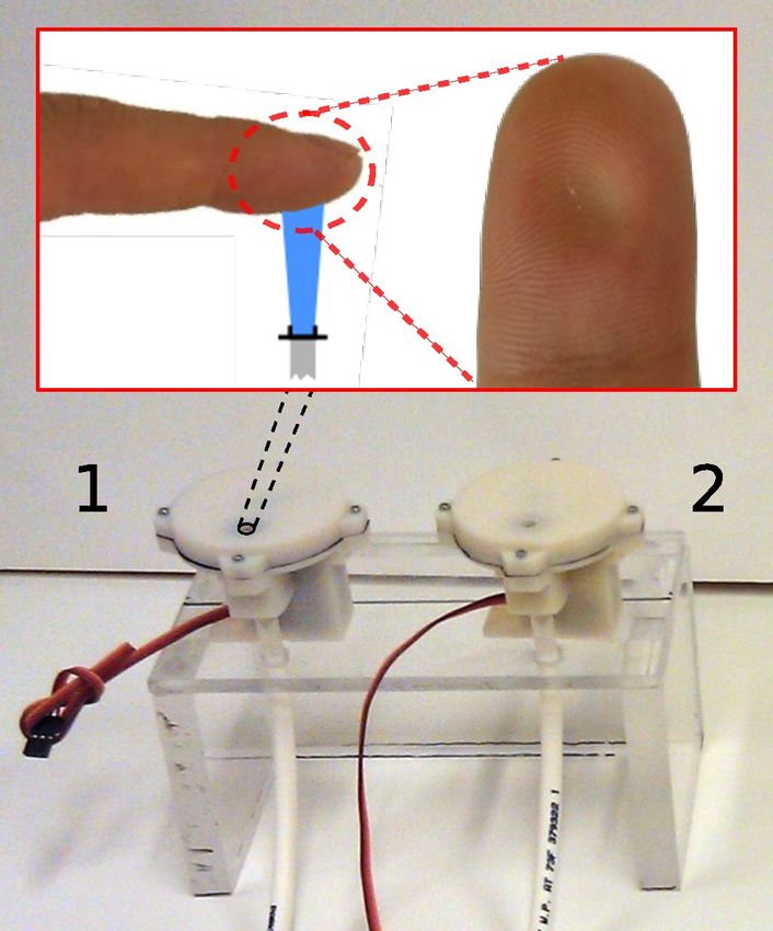
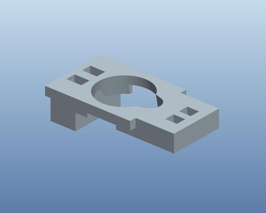
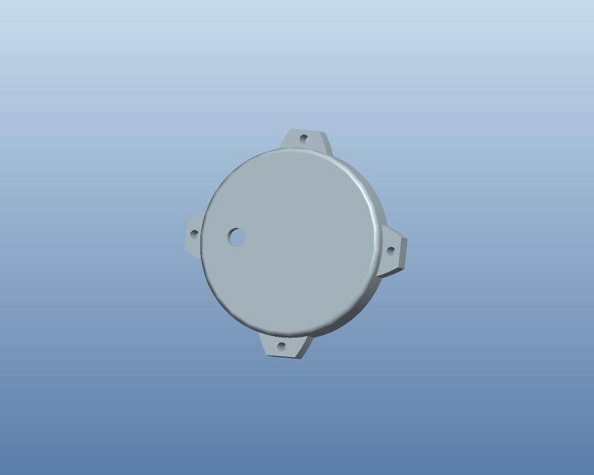
(a) Casing              (b) Continuous Disk              (c) Discrete Disk                   (d) Plug                          (e) Casing Lid

Figure 2: Components of the pneumatic air-jet lump display. (a) Casing: Encloses the servo motor and receives compressed air from the
pressure regulator. (b,c) Continuous and discrete aperture disks: Aperture disks sit flush with the casing top surface and fix to the servo motor
shaft. Servo-initiated rotation of disks changes the effective aperture size. (d) Plug: Stabilizes the servo inside the casing, preventing unwanted
axial shifts. (e) Casing Lid: Seals the display using a rubber o-ring and four binding sites. Has a hole on the top through which the air-jet escapes.

flexible sheet dampens the noticeable effects of changing control
parameters. As a result, we elected to design a display with the
intention of stimulating directly on the surface of the skin.
   In its simplest form, our air-jet display (Fig. 1a) can be described
and controlled using two degrees of freedom (Fig. 1b): (1) the sup-
ply pressure provided to the display, and (2) the size of the aper-
ture through which the air escapes. We hypothesize that the aper-
ture size and the air pressure will correspond in some way to the
perceived size and stiffness of the lump, respectively. Preliminary
psychophysical evaluation has focused on the just noticeable differ-            Figure 3: A typical air-jet opening envelope develops in a conical
ence (JND) of pressure perception [1]. Unlike balloon-type lump                 shape with a constant coefficient of proportionality of 11.8 ◦ . The jet
displays [4] that can not effectively decouple lump size and stiff-             radius (R) is a function of the distance from the outlet (x1 ) and the
ness, the air-jet display gives independent control over perceived              aperture diameter (d).
lump size (aperture size) and stiffness (air pressure).

                                                                                                                             ◦ 5
3     D EVICE D ESIGN   AND   C ONTROL                                                           R(X1 , d) = tan(11.8 ) X1 + d                   (1)
                                                                                                                               2
The air-jet display is comprised of five main parts: a main outer cas-             We fixed X1 to be 14 mm then identified the largest aperture di-
ing (Fig. 2a), a circular disk to control aperture size (Figs. 2b or 2c),       ameter (d) which kept the jet radius (R) near 5 mm. This resulted in
a small servo motor to rotate the aperture disk (not shown), a stabi-           a maximum aperture diameter of d = 3.97 mm. We selected 4.5 mm
lizing plug to secure the motor and reduce unwanted motion of the               as our maximum aperture size, which results in a jet diameter of
disk during operation (Fig. 2d), and the casing lid (Fig. 2e), which            ≈ 10.5 mm, less than the width of the average index fingerpad.
seals the device. All components shown in Fig. 2 were designed                     We selected eight aperture diameters ranging from 1.0 mm to
using ProEngineer (PTC, Needham, MA USA), and manufactured                      4.5 mm, equally spaced by 7/16 mm, except between the small-
using a u-Print rapid prototyping 3D printer (Dimension, Inc., Eden             est two apertures, where this space is doubled. The center of each
Prairie, MN USA). The uPrint uses ABSplus TM thermoplastic as                   aperture was fixed radially 15 mm from the center and arranged cir-
its building material (tensile strength of 5,300 psi). All designed             cumferentially around the disk such that the area of the apertures
components underwent several iterations, each aimed at reducing                 increased linearly with rotation angle (Fig. 5). The angular place-
the size and weight of the display, as well as minimizing air leaks.            ment of each aperture on the discrete disk is given by
   Aperture size is controlled using a TowerPro MG-90 servo mo-
tor (Tower-Pro Electron Co. Ltd, Shenzhen, China), which sits cen-                                             θ = γ ∆θ + θmin ,                            (2)
trally in the casing and rotates the aperture disk to a desired posi-
                                                                                where γ and ∆θ are determined entirely from the minimum (rmin )
tion to change the effective aperture size. Air pressure is controlled
                                                                                and maximum (rmax ) aperture size at θmin = 10◦ and θmax = 180◦ ,
using an electronic pneumatic regulator (SMC-ITV2031-21N2L4,
                                                                                respectively:
SMC Corporation, Noblesville, IN, USA) which provides step-less
control of air pressure (0.05 - 0.5 MPa) proportional to an electrical                                              2           2
signal (0 - 5 V), with a maximum flow rate of 1500 L/min. The de-                                                  raperture − rmin
                                                                                                              γ=      2 − r2
                                                                                                                                                           (3a)
sign and purpose of each component of the pneumatic air-jet lump                                                     rmax  min
display is described in greater detail in the sections that follow.
                                                                                                               ∆θ = θmax − θmin                            (3b)
3.1    Discrete Aperture Disk
Since the display was designed specifically for single finger stim-             3.2 Continuous Aperture Disk
ulation, we needed to carefully select a fixation distance from the             In addition to the discrete aperture disk, we evaluated an alterna-
outlet, and aperture sizes that keep the jet diameter smaller than the          tive “continuous” aperture disk by creating a circumferential slot
width of the index fingerpad. Jet theory explains that for any jet              that gradually changes width around the circumference of the disk
penetrating a fluid of the same density (e.g. air), the jet envelope            (Fig. 4a). The outer (ro ) and inner (ri ) curves defining the changing
adopts a conical shape (Fig. 3), and the opening angle of the jet en-           shape of the continuous slot are defined by
velope remains constant (11.8◦ ) regardless of aperture diameter or
discharge speed [5]. The jet radius (R) at a given distance from the                                      s
outlet (X1 ) originating from an aperture of diameter (d) is given by                                         (rmax )2 (θ − θo ) − (rmin )2 (θ − θ f )
                                                                                        ro,i (θ ) = r ±                                                ,    (4)
the equation                                                                                                                (θ f − θo )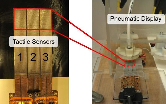
(a)                                                                             (b)

Figure 4: (a) Calculation of effective area of continuous disk. Radii rmin and rmax are the radii of the smallest and largest circles that can be
inscribed at slot ends. The center of the smallest circle is at (r, θo ), and the center of the largest circle is at (r, θ f ) in polar coordinates. Circle
rb represents the aperture size on the casing through which the air-jet interfaces with the continuous disk slot. Radii ro (θ ) and ri (θ ) represent
the distance from the disk center to the outer and inner curves, respectively, at a given θ . Ab represents the effective area of the intersection
between the continuous slot and the area of the base aperture. (b) Effective area of continuous disk aperture at varying values of θ .

                                                                                 function is illustrated clearly in Fig. 4b in the disk marked by 10◦ .
                                                                                 When the continuous disk reaches 18◦ , the endpoint of the small
                                                                                 end of the slot enters within the perimeter of the base aperture,
                                                                                 causing a change in the relationship between area and angle. The
                                                                                 piecewise equation provides a means to control the rotation of the
                                                                                 disk in a linear fashion in software. The user inputs a desired area,
                                                                                 and the software calculates the corresponding angular position.
                                                                                 3.3 Casing and Servo Motor
                                                                                 The servo motor rotating the aperture disks has a rotation range of
                                                                                 170◦ , a maximum speed of 545◦ per second, and 31 oz-in of torque.
                                                                                 A servo motor was used instead of other motor types because servos
                                                                                 produce a relatively high amount of torque for their small size and
                                                                                 weight. We use a Phidgets Advanced Servo 1066 servo controller
                                                                                 (Phidgets, Inc., Calgary, Alberta, Canada) to communicate with the
                                                                                 servo. Servo motor position is controlled by providing pulse widths
                                                                                 of a specified duration, which map linearly to shaft angle. Mini-
                                                                                 mum and maximum pulse widths used to control the angular posi-
Figure 5: Effective aperture area vs. angle of rotation for the discrete         tion of the servo shaft were 600 and 2350 µs, respectively.
and continuous aperture disks. Discrete apertures display a linear                  The casing houses the servo motor internally, and serves as a
relationship between aperture area and angular placement on the                  medium for transferring pressurized air from the pressure regulator
disk. The continuous aperture slot has two sections with differing               through the aperture disk. Air is fed from the pressure regulator
behaviors: A linear behavior is observed up to θ = 18◦ , after which             through 6.4 mm outer diameter (O.D.) polyurethane tubing, where
the curve can be expressed using a power relation.                               it connects to the underside of the casing by means of a push-to-
                                                                                 connect fitting. The air passes through the aperture disk and exits
where rmax and rmin refer to the radius of the circle that can be in-            through the 5 mm diameter hole on the casing lid. The display
scribed at the large and small ends of the slot, respectively. We                contains two Buna-N O-rings (each 2 mm thick) designed to seal
computed the area of the intersection (Ab ) between the base aper-               the system and force all pressurized air through the aperture disk
ture (rb ) and the continuous slot (ro,i (θ )) for all values of θ . As the      (Fig. 6, bottom). One O-ring (11 mm O.D.) is placed around the
slotted disk is rotated with respect to the base aperture, the effective         hole in the lid casing and seals between the lid and aperture disk,
area changes (Fig. 4b). The radii rmin and rmax were set so that the             and the other (44 mm O.D.) placed around the circumference of the
effective intersection area at minimum and maximum angular disk                  lid, sealing the lid and casing. The seals are compressed by screw-
angles were approximately equal to the areas at the endpoints of                 ing the lid to the casing with four small screws. Both O-rings fit
the discrete disk. Unlike the discrete disk which changes aperture               into circumferential grooves of rectangular cross-section, and were
area linearly with θ , the continuous disk exhibits a more complex               designed to provide 25% compression to the O-ring. This allows
behavior. Fig. 5 shows the effective aperture area (Ab ) as a function           sufficient compression to provide effective air sealing without in-
of disk rotation (θ ). This relationship is described by the piecewise           creasing the friction level on the disk beyond the ability of the servo
function                                                                         motor to rotate. Each display weighs 53 grams.
                            (
                             aθ − b     if θ ≤ 18◦                               4 D EVICE C HARACTERIZATION
                     Ab =                                              (5)       We used an array of capacitive tactile sensors (DigiTacts, Pressure
                              cθ n      if θ > 18◦                               Profile Systems, Los Angeles, CA USA) to quantitatively measure
                                                                                 the output of the air-jet lump display using both discrete and contin-
with a linear fit for small θ , and a power function fit for larger θ .          uous aperture disks. The tactile sensor array is comprised of three
Coefficients for equation (5) are shown in Fig. 5. The piecewise                 smaller sensors arranged contiguously to form a 6 × 12 array of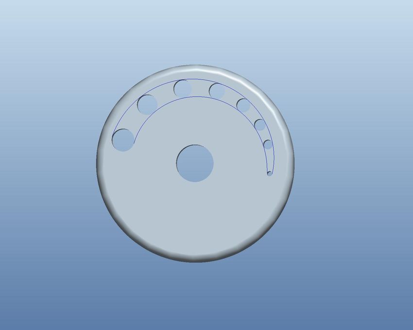
Figure 7: (Left) Tactile sensors forming the sensing array; the area
                                                                          encircled by the red box represents the location of the sensing ele-
                                                                          ments. (Right) Experimental setup used to measure the peak pres-
                                                                          sure of the impinging air-jet.

Figure 6: Pneumatic air-jet lump display. (Left) The continuous and
discrete display devices are mounted on the display unit. (Right)
Electronics box houses the pressure regulator, servo controller
board, and DAQ breakout board. (Bottom) Two sealing rings inte-
grated into the bottom side of the opened casing lid.                                            (a) Discrete Aperture Disk

tactile sensing elements (Fig. 7, left). The display was inverted and
placed 14 mm above the sensors with the output centered over the
tactile sensor array (Fig. 7, right).
   For the discrete disk, each aperture size (1.9, 2.3, 2.8, 3.2, 3.8,
4.1, and 4.5 mm) was measured at each supply pressure level (10,
20, 30, and 40 psi) first in ascending, then descending order. Prior
                                                                                                (b) Continuous Aperture Disk
to each measurement pair (aperture size, pressure), the pressure was
set to zero and the sensors were baselined to minimize sensor noise.
                                                                          Figure 8: Tactile images recorded at 40 psi supply pressure. (a) Tac-
Each measurement consisted of 150 samples of tactile data. The            tile images from discrete aperture disk. The aperture size ranges
1.0 mm aperture size was not used since the small diameter created        from 1.9mm (left) to 4.5mm (right). (b) Tactile images from continu-
a large resistance which compromised the seals of the display.            ous aperture disk. Area of effective aperture for each image matches
   For the continuous disk, we measured data at the angles where          the area of the equivalent discrete aperture.
the effective area of the continuous slot matched the areas of the dis-
crete apertures. Those values of θ were obtained from Equation (5).
At each measurement angle, data was recorded in the same manner           contained the maximum pressure value, and fit a Gaussian to the
as the discrete case. For both discrete and continuous disks, supply      data. Fig. 9 shows the Gaussian fits to the tactile data and illustrates
pressures up to 46 psi were attainable.                                   the changing shape of the pressure profile at every combination of
                                                                          aperture size and supply pressure. The maximum of the Gaussian
5     R ESULTS   AND   D ISCUSSION                                        curves are not always at the center of the x-axis, in part because of
5.1    Tactile Images and Pressure Distributions                          discretization and also because the aperture was not centered per-
                                                                          fectly on top of the sensors.
All 150 samples from a single measurement pair are averaged to
                                                                             Although subjective, the authors feel that the output of the dis-
form a “tactile image”, where the average value for each sensor
                                                                          play generates a compelling lump percept as the skin of the fin-
element is plotted in the same spatial configuration as the actual
                                                                          gerpad is indented in a spherical pattern. Peak pressure is consis-
tactile sensor. Each tactile image is then processed using bilinear
                                                                          tently perceived at the center of the stimulus. The air-jet display
interpolation. Fig. 8 shows tactile images recorded at a constant
                                                                          output feels slightly less spherical for the smaller slot size of the
supply pressure of 40 psi for both discrete (Fig. 8a) and continuous
                                                                          continuous aperture disk, but complete psychophysical tests will be
(Fig. 8b) aperture disks. Tactile images for smaller supply pressures
                                                                          required to evaluate the perceptual extents of the display more rig-
are not shown. The change in size of the air-jet pressure profile of
                                                                          orously.
the discrete disk apertures is clearly visible. Additionally, tactile
images show circular profiles which reflect the circular nature of
the aperture. One consequence of using a continuous slot is that the      5.2   Aperture-Pressure Curves
shape of the effective aperture becomes increasingly non-circular as      We extracted the maximum pressure value from the tactile im-
the disk rotates toward the smaller end of the slot. This results in a    age produced by each aperture and supply pressure combination.
slightly different pressure output profile that can be seen in Fig. 8b.   These “peak pressure values” for discrete (Fig. 10a) and continuous
   The air-jet lump display is a type of short impingement jet, which     (Fig. 10b) aperture disks show similar magnitudes, but slightly dif-
are known to exhibit a Gaussian pressure profile upon impinge-            ferent behavior with varying aperture size. For both aperture disks,
ment [12]. For each tactile image, we identified the row of data that     P1-P4 represent supply pressures of 10-40 psi, respectively. These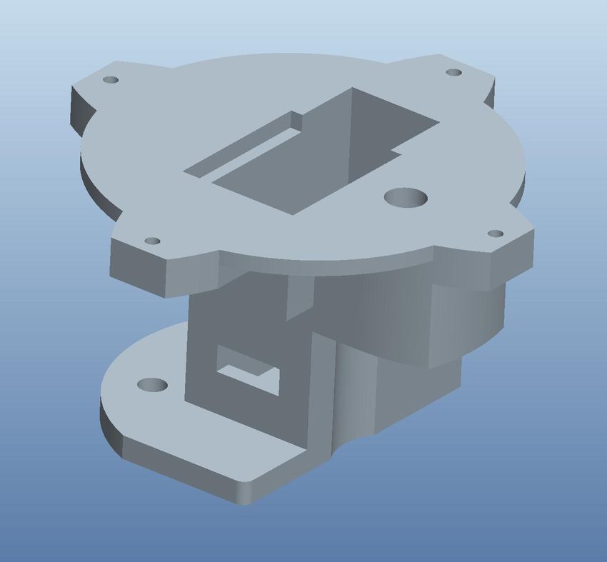
(a) Discrete

Figure 9: Pressure profiles for all supply pressures and aperture
sizes. Data points represent the row of recorded tactile sensor val-
ues spanning the sensor which contained the peak pressure value.
Red dashed lines are Gaussian fits for discrete disk tactile data.

                                                                                                         (b) Continuous
plots represent the maximum output pressure that can be achieved
across the range of aperture sizes and supply pressures. The peak
                                                                           Figure 10: Tactile sensor peak pressure values recorded at each
pressure is almost constant for the lowest supply pressure (10 psi)
                                                                           aperture and supply pressure. Supply pressures P1-P4 correspond
across all apertures. Smaller apertures give a lower peak pressure         to 10-40 psi, respectively. (a) Discrete disk peak pressure values (b)
than the larger apertures. Sharper changes in peak pressure values         Continuous disk peak pressure values.
are observed between apertures 1.9 mm and 3.2 mm. The smallest
aperture (1.0 mm) data was again omitted from the plot for reasons         C-0050, Johns Hopkins University, and a National Science Foun-
described previously.                                                      dation Graduate Research Fellowship.
6 C ONCLUSIONS AND F UTURE W ORK                                           R EFERENCES
We have designed an air-jet lump display capable of displaying              [1] M. Bianchi, J. C. Gwilliam, A. Degirmenci, and A. Okamura. Char-
lumps with different sizes and pressures by modulating the aper-                acterization of an Air Jet Haptic Lump Display. In Proc. Int’l Conf. of
ture size and supply pressure, respectively. We have collected tac-             the IEEE Engineering in Medicine and Biology Society, pages 3467–
tile data using capacitive pressure sensors in order to quantitatively          3470, 2011.
characterize the output of the display. Tactile data shows that the         [2] L. Boguslawski and C. O. Popiel. Flow structure of the free round
display is capable of altering the air-jet pressure, as well as the size        turbulent jet in the initial region. Journal of Fluid Mechanics,
of the impinging air-jet. Additionally, initial evaluations of the dis-         90(03):531, 2006.
play output, although subjective, have yielded compelling spheri-           [3] V. G. Chouvardas, A. N. Miliou, and M. K. Hatalis. Tactile displays:
cal, “lump-like” percepts. The accompanying videos illustrate the               Overview and recent advances. Displays, 29(3):185–194, 2008.
display mechanism and the accompanying tactile data (both contin-           [4] M. Culjat, C. H. King, M. Franco, J. Bisley, W. Grundfest, and
                                                                                E. Dutson. Pneumatic balloon actuators for tactile feedback in robotic
uous and discrete) as the aperture disk is rotated.
                                                                                surgery. Industrial Robot, 35(5):449–455, 2008.
    Future work will focus on rigorous psychophysical tests which
                                                                            [5] B. Cushman-Roisi. Turbulent Jets. In Environmental Fluid Mechan-
determine the just noticeable difference (JND) for supply pressure              ics, chapter 9. John Wiley and Sons, Hanover, New Hampshire, 2010.
and aperture size. This will allow additional tuning of control algo-       [6] R. Howe, W. Peine, D. Kantarinis, and J. Son. Remote palpation
rithms, and increase the accuracy of the percepts produced from the             technology. IEEE Engineering in Medicine and Biology Magazine,
display. One drawback of an air-jet display is the noise it produces,           14(3):318–323, 1995.
especially when impinging on a surface or at higher supply pres-            [7] K. Inoue, F. Kato, and S. Lee. Haptic device using flexible sheet
sures. There are measures which can be taken to reduce the noise                and air jet for presenting virtual lumps under skin. In Proceedings
(e.g. plastic box, foam), although noise may be more or less of a               IEEE/RSJ Int’l Conf. on Intelligent Robots and Systems, pages 1749–
concern depending on the application in which the air-jet display is            1754, 2009.
used. Additionally, the size of the device could be reduced from its        [8] J. Killebrew, S. Bensmaia, J. Dammann, P. Denchev, S. Hsiao,
current state. Since pressure regulation occurs upstream, the only              J. Craig, and K. Johnson. A dense array stimulator to generate ar-
mechanical component of the display is the servo used to change the             bitrary spatio-temporal tactile stimuli. Journal of Neuroscience Meth-
aperture size. We would like to explore other novel mechanisms to               ods, 161(1):62–74, 2007.
change the aperture size which could potentially occupy much less           [9] M. V. Ottermo, O. Stavdahl, and T. A. Johansen. A remote palpa-
space and therefore make the display much smaller.                              tion instrument for laparoscopic surgery: design and performance.
    A pneumatic-based approach is a largely unexplored and                      Minimally Invasive Therapy and Allied Technologies, 18(5):259–272,
untested strategy for a targeted haptic display task such as lump               2009.
rendering in RMIS applications. As we understand more about the            [10] S. Overduin and P. Servos. Distributed digit somatotopy in primary
                                                                                somatosensory cortex. NeuroImage, 23(2):462–472, 2004.
air-jet stimulus, how it is controlled and perceived, it can be used in
                                                                           [11] K. Shimoga. A survey of perceptual feedback issues in dexterous tele-
applications where the goal is to display a spherical shape to finger-
                                                                                manipulation. II. Finger touch feedback. In Proc. IEEE Virtual Reality
pad. Additionally, an array of air-jets can be used to display large            Annual International Symposium, pages 271–279, 1993.
spatial pressure variations.                                               [12] C. V. Tu and D. H. Wood. Wall pressure and shear stress measure-
                                                                                ments beneath an impinging jet. Experimental Thermal and Fluid
ACKNOWLEDGEMENTS
                                                                                Science, 13(4):364–373, 1996.
This work was supported in part by the US Army Medical Re-
search and Material Command under Contract No. W81XWH-11-
You can also read