Designing and dimensioning of a new type of pump that can be used in the field of land reclamation - E3S Web of Conferences
←
→
Page content transcription
If your browser does not render page correctly, please read the page content below
E3S Web of Conferences 286, 04001 (2021)                                 https://doi.org/10.1051/e3sconf/202128604001
TE-RE-RD 2021

      Designing and dimensioning of a new type of
      pump that can be used in the field of land
      reclamation
      Mariana Mirela Stoican (Prisecaru) ,*and Nicolae Băran1
      1
       University Politehnica of Bucharest, Faculty of Mechanical Engineering and Mechatronics, Splaiul
      Independenței, no. 313, Bucharest, Romania

                    Abstract. The findings made during the operation of the pumping stations
                    within the land improvement arrangements, energy balances,
                    measurements performed and low efficiencies that are currently between
                    50% -77%, it is necessary to continue research in order to improve
                    parameters and replacement of existing aggregates with energy efficient
                    equipment. Thus, theoretical and experimental research was performed in
                    order to improve the projected theoretical parameters of a rotating
                    volumetric pump. For a certain water flow rate that should be transported
                    to irrigate an area of agricultural land or discharged from a land area
                    equipped with drainage works, a rotating pump is dimensioned and the
                    flow rate according to the number of rotations diagram is plotted.

      1 Introduction
          A current research direction is to improve the performance of the machines that
      transports fluids. Optimizing the interior architecture of working machines is a very
      important issue, a problem studied both in our country and abroad.
          Both motor and working machines evolve over time in the following direction:
          - For motor machines, the aim is to produce the maximum mechanical work yielded
      outside.
          - For working machines, the minimum consumption of mechanical work from the
      outside is sought.
          The architectural problem of rotors, consists in finding solutions for optimizing their
      geometry and the choice of parameters that lead to a more efficient fluid transport.
          For rotating working machines with profiled rotors, the problem regarding the
      architecture of the rotor is the optimization of its geometry and the choice of parameters
      that lead to a more efficient fluid transport.
          Minimizing the driving power of volumetric pumps with profiled rotors and finding a
      new architecture of the profiled rotor are key elements in the conception and designing of a
      new rotating machine.

      *
          Corresponding author: mirela.prisecaru@yahoo.com

© The Authors, published by EDP Sciences. This is an open access article distributed under the terms of the Creative Commons
Attribution License 4.0 (http://creativecommons.org/licenses/by/4.0/).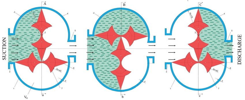
E3S Web of Conferences 286, 04001 (2021) https://doi.org/10.1051/e3sconf/202128604001
TE-RE-RD 2021
Rotating pumps are included in the category of rotating working machines for liquid
circulation.
In technics, there are two main criteria for pumps classification [1] [2]:
I. According to the operation principle;
II. According to the driving mode.
Ⅰ. According to the operation principle, two categories are distinguished:
A. Volumetric pumps;
B. Non-volumetric pumps.
The main feature of volumetric pumps is the relative independence of the flow rate from
the suction pressure values and especially at the pump discharge. For this type of hydraulic
generators, the flow rate is given by the sum of the elementary volumes pumped in the unit
of time.
Ⅱ. There are three categories of pumps according to the driving mode [2]:
- Electro-pumps; pumps; turbopump.
Table 1 classifies the pumps according to the operating principle [3].
Table 1. Categories of pumps.
a) Single cylinder pumps
b) Polycylindrical pumps
Piston pumps
c) Pumps with axial pistons
d) Blade pumps
A) Volumetric
pumps e) Gear pumps
f) Screw pumps
Rotating pumps
g) Lobe pumps
h) Pumps with profiled rotors
Centrifugal pumps
B) Non-volumetric
pumps
Axial pumps
Next, the paper will study the category of rotating volumetric pumps, namely, the one
with profiled rotors (h).
2 The pump sketch and the operation principle
The main dimensions of the pump, which has two identical rotors, must first be
determined:
- l - the rotor length [m];
- Rr - the machine rotor radius [m];
- z - the height of the rotating piston [m].
The case radius (Rc) results from the sum of the rotor radius (Rr) and the height of the
piston (z) (figure 1).
R
c Rr z m (1)
What is the connection between z and Rr? How big can z be in relation to Rr?
2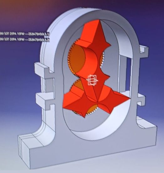
E3S Web of Conferences 286, 04001 (2021) https://doi.org/10.1051/e3sconf/202128604001
TE-RE-RD 2021
To solve this problem, we will consider a single piston (5) positioned on the lower rotor (1)
[4] [5].
Fig. 1. Calculation notations
1 - rotor located at the bottom; 2 - rotor located at the top;
3 - the driving shaft of the machine; 4 - the driven shaft of the machine;
5 - rotating triangular piston.
The radius of the rotor (1) of the rotating machine is extended by a length (z) so that the
line O1B reaches at point A the rotor (2). In this way, the sealing between the two rotors is
ensured by direct contact between the side surfaces of the rotors.
Analyzing the triangle O1O2A will result:
2
O1O 2 AO 2 2 AO12 (2)
(2 R r z ) 2 R r 2 ( R r z ) 2 (3)
relations that become:
z 3 2 R r z 2 Rr 2
0 (4)
If in relation (4) the derivative is performed according to the height of the rotating
piston (z) one can obtain:
z Rr (5)
That is, z is maximum when it becomes equal to the rotor radius Rr; from the conditions
of sealing and execution of the rotors, it is chosen z Rr .
The rotating volumetric pump with profiled rotors consists of (figure 2) two profiled
rotors (3, 7), which rotate at the same speed inside the cases (1, 4); the profiled rotors are
engaged by two gears (8) mounted inside the side wall of the pump case, thus ensuring their
synchronization. The shaft drives the lower rotor through a flange fixed with rotor screws;
the flange rotates inside the side wall of the case (figure 2.b) [6] [7].
3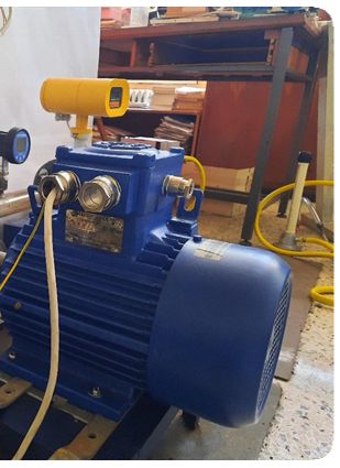
E3S Web of Conferences 286, 04001 (2021)                           https://doi.org/10.1051/e3sconf/202128604001
TE-RE-RD 2021

               Fig. 2. Cross section (a) and longitudinal section (b) through the rotating machine
                         a: 1 - lower case; 2 - fluid suction connection; 3 - upper rotor;
               4 - upper case; 5 - fluid discharge connection; 6 - rotating piston; 7 - lower rotor;
                            b: 8 - gears; 9 - bearings; 10 - side wall (left) of the case;
                          11– intermediate wall; 12 - bearing cover; 13 - driving shaft;
                                     14 - sealing caps; 15 - clamping screws.

          The technical solution shown in figure 2 has the following characteristics:
          a) The height of the piston is approximately equal to the radius of the rotor, thus
      increasing the useful volume of fluid conveyed;
         b) The shaft for each rotor does not penetrate inside the rotor, so z → Rr.
         For the construction of the rotors, a mathematical calculation program was elaborated,
      which specifies the shape of the rotor contour, and their execution was performed with the
      help of a numerically controlled machine tool (C.N.C.).
         Figure 3 shows the location of the rotors inside the case.

                                                       4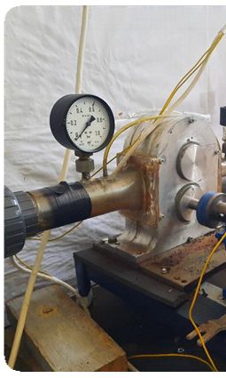
E3S Web of Conferences 286, 04001 (2021) https://doi.org/10.1051/e3sconf/202128604001
TE-RE-RD 2021
Fig. 3. Axonometric view of the case with the two rotors mounted inside it.
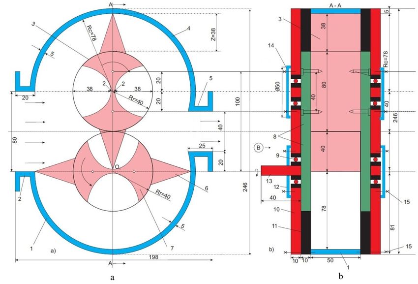
Figure 4 shows the operation of the rotating volumetric pump with profiled rotors. One
can observe that after a 180° rotation the useful volume of the transported fluid (Vu) is
discharged into the discharge chamber.
Fig. 4. Operating principle of the rotating volumetric machine
1 - lower case; 2 - fluid suction connection; 3 - upper rotor;
4 - upper case; 5 - fluid discharge connection; 6 - rotating piston; 7 - lower rotor.
The useful volume is the volume between two pistons and the case (figure 4.a).
When operating as a rotating volumetric pump with profiled rotors, two volumes (Vu)
will be transported from the suction to the discharge at a complete rotation of the shaft.
Vu = 2 Rc 2 Rr 2 l m 3 / rot (6)
where: l - the rotor length [m].
The case radius (Rc) is the sum of the rotor radius (Rr) and the height of the piston (z):
Rc = Rr + z m (7)
The volumetric flow rate of the fluid transported by the pump will be:
n
V l z z 2 Rr r m 3 / s (8)
30
One can observe that the volumetric flow rate increases linearly with the length (l) and
the rotor radius (Rr) and with the speed (n).
In the laboratory of the technical department of Faculty of Mechanics within the UPB, a
prototype of this volumetric pump with the following characteristics was designed and built
[8] [9]:
- the rotor length: l = 0.05 [m];
- the rotor radius: Rr = 0.04 [m];
- the height of the rotating piston: z = 0.038 [m].
So, the case radius will be:
Rc = Rr + z = 0.04 +0.038 = 0.078 m (9)
An overview of the pump mounted on the test stand is shown in Figure 4.
5
E3S Web of Conferences 286, 04001 (2021) https://doi.org/10.1051/e3sconf/202128604001
TE-RE-RD 2021
Fig. 5. Overview of the volume
volumetric pump in the test stand.
Equation (8) is repeated, which specifies the flow rate of the pump, the rotating pistons
are considered to have a triangular shape, the area of the section between the base of the
prism and the rotor is neglected,
eglected, and the volume of this prism will be:
1 1
V p = Abase l = b z l = 0.03 0.038 0.05 V p = 0.0285 10 -3 [m3 / rot ] (10)
2 2 ;
The theoretical flow rate of the machine will be lower with Vp.
n
Vu = lz z + 2Rr -V p r [m 3 / s ] (11)
30
500
V = 3.14 0.05 0.038 0.038 + 2 0.04 - 0.0285 10 -3
30 (12)
3
V = 0.011258 [ m / s ] 40.529 [ m / h ] 3
(13)
For the pump data presented above, choosing the operating spee speed of the pump as 200 ...
500 [rpm] the values in Table 2 resulted.
Table 2. The values of V f ( nr ) .
nr [rpm] 200 300 400 500
V dm3 / m in 270.18 405.3 540.42 675.48
V m3 / h 16.211 24.317 32.423 40.529
Based on the theoretical data in Table 2 and following the experimental researches, the
graph of the function V f (nr ) was drawn in Figure 6.
6E3S Web of Conferences 286, 04001 (2021) https://doi.org/10.1051/e3sconf/202128604001
TE-RE-RD 2021
V dm3 / min
700
650
600
550
500
450
400
theoretical values
350
300 experimental values
250
200
150
100
100 150 200 250 300 350 400 450 500 550 nr [rpm]
Fig. 6. The graphs of the function V f ( nr )
1 - theoretical values; 2 - experimental values.
Figure 6 shows that the two graphs are very close; as a result, the volumetric efficiency
will be [10]:
V
v t (14)
V r
Approximately, as the average value, it will be v 0.95 .
3 The use of the constructive solution of the rotating volumetric
pump in the field of land reclamation
If the characteristic sizes of the laboratory prototype are multiplied by 10, one can
obtain:
- the rotor length: l = 0.5 [m];
- the rotor radius: Rr = 0.4 [m];
- the height of the rotating piston: z = 0.38 [m].
The case radius will be:
Rc = Rr + z = 0,4 +0,38 = 0,78 m (15)
Substituting these values in relation (11), for different speeds 200 ... 500 [rpm] the data
in table 3 are obtained.
Table 3. The values of V f ( nr ) .
nr [rpm] 200 300 400 500
V m3 / h 16211.712 24317.568 33790.056 40529.280
7E3S Web of Conferences 286, 04001 (2021) https://doi.org/10.1051/e3sconf/202128604001
TE-RE-RD 2021
V m3 / h
40,000
35,000
30,000
25,000
20,000
15,000
10,000
100 200 300 400 500
nr [rpm]
Fig. 7. The graphs of the function V f ( nr )
This flow rate for nr = 400 [rpm] can ensure the irrigation of 28 hectares of agricultural
land, once a day with 10 l /m2.
4 Conclusion
a. Rotating working machines have the advantage of converting the motor torque
received from the shaft into potential pressure energy with minimal losses.
b. The advantages of this original construction solution is that it can transport high
flows rate water with lower energy consumption compared to existing pumps in irrigation
stations.
c. As a result of the theoretical and experimental research carried out in the laboratory,
the effective efficiency of the machine of 78% resulted. The actual efficiency of the
machine is influenced by the nature of the fluid transported by the viscosity and of the
machine speed.
d. Thus, we conclude that the driving power is influenced by the flow rate (i.e., by the
parameters mentioned above) by the increase in pressure (Δp) achieved by the rotating
machine between suction and discharge, the nature of the transported fluid.
e. Volumetric pump with profiled rotors can be used in the field of land reclamation, in
wastewater treatment plants, in: mining, energy, petrochemical industry.
f. There is a good concordance between theoretical data and those experimentally
determined.
References
1. N. Băran, P. Răducanu, a.o., Bases of Technical Thermodynamics, Technical
Thermodynamics (in Romanian), POLITEHNICA PRESS Publishing House,
Bucharest (2010).
2. C. Ţurcanu, N. Ganea, Volumetric Pumps for Liquids, (in Romanian), Technical
Publishing House, Bucharest (1980).
8E3S Web of Conferences 286, 04001 (2021) https://doi.org/10.1051/e3sconf/202128604001
TE-RE-RD 2021
3. M. Exarhu, Pneumatic and hydraulic machine and installations, (in Romanian), SC.
ANDOR SRL, Bucharest, 2011.
4. N. Băran, A. Detzortzis, M. Hawas, D. Besnea, The correlation between the rotor
shape and the energetic performance of a rotating machine with profile rotors, The
Romanian Review Precision Mechanics, Optics & Mechatronics, no. 45,18-26 (2014).
5. M. Hawas, N. Băran, A. Detzortzis, Influence of the rotor architecture and of the speed
on the volumetric efficiency of a new type of rotating volumetric machine, Advanced
Materials Research, Trans Tech Publications, Switzerland, 905, 487-491, (2014).
6. M. Hawas, The influence of fluid viscosity on the performance of rotating machine
with profiled rotors, PhD Thesis, Faculty of Mechanical Engineering and
Mechatronics, University Politehnica of Bucharest (2015).
7. A. Motorga, Influence of constructive and functional parameters on the performances
of rotating machines with profiled rotors, PhD Thesis, Faculty of Mechanical
Engineering and Mechatronics, University Politehnica of Bucharest (2011).
8. N. Băran a.o., Bases of Technical Thermodynamics, (in Romanian), POLITEHNICA
PRESS Publishing House, Bucharest, 3 (2010).
9. N. Băran, A. Motorga, D. Duminică, Research Regarding the Building of an
Experimental Setup for the Testing of a New Type of Rotating Machine with Profiles
Rotors, Mechatronics Magazine, no.1, 27-30, (2011).
10. N. Băran, D. Besnea, A. Motorga, Elements of computing the architecture and
manufacturing technology for a new type of profiled rotor, Proceedings International
Conference, 6th Workshop on European Scientific and Industrial Collaboration on
promoting Advanced Technologies in Manufacturing, WESIC’08, Bucharest, 233-241
(2008).
9You can also read