Simulation of cut off characteristics of 2.45 GHz microwave inside the open-ended conductor cylindrical pipe
←
→
Page content transcription
If your browser does not render page correctly, please read the page content below

Journal of Physics: Conference Series

PAPER • OPEN ACCESS

Simulation of cut off characteristics of 2.45 GHz microwave inside the
open-ended conductor cylindrical pipe
To cite this article: Apassara Rachpibul and Mudtorlep Nisoa 2021 J. Phys.: Conf. Ser. 1719 012049

View the article online for updates and enhancements.

                              This content was downloaded from IP address 46.4.80.155 on 01/02/2021 at 06:23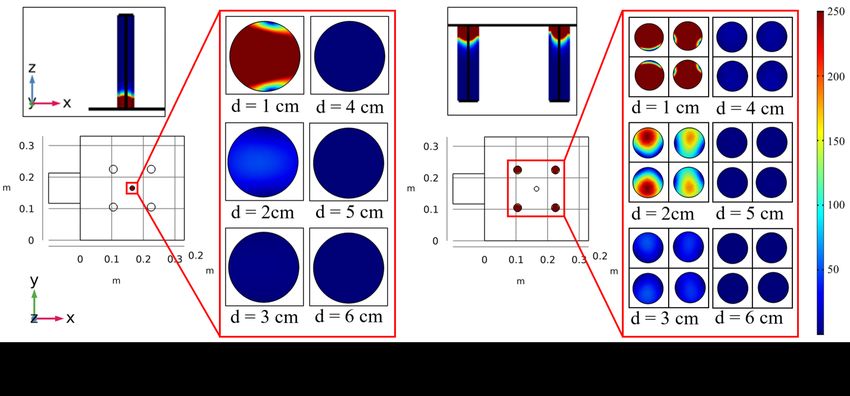
Siam Physics Congress (SPC) 2020                                                                                IOP Publishing
Journal of Physics: Conference Series                         1719 (2021) 012049          doi:10.1088/1742-6596/1719/1/012049

Simulation of cut off characteristics of 2.45 GHz
microwave inside the open-ended conductor
cylindrical pipe
                      Apassara Rachpibul1,∗ and Mudtorlep Nisoa1,2
                      1
                       School of Science, Walailak University, Nakhon Si Thammarat, 80160, Thailand
                      2
                       Center of Excellence in Plasma Science and Electromagnetic Wave, Walailak University,
                      Nakhon Si Thammarat, 80160, Thailand
                      *E-mail: r.apassara.k@gmail.com

                      Abstract. For a realtime measurement of moisture contents and temperature profiles of a
                      sample inside a microwave oven, Sensors and open-ended pipes are equipped to the microwave
                      system, allowing to measure those parameters from other ends of the pipes. The main role of the
                      pipes is to reduce the microwave wave from leaking out to the environment and the interference
                      with measuring equipment. In this research, a model of a microwave system with five installed
                      pipes is simulated using COMSOL Multiphysics. The microwave cavity is modelled to be a
                      cube with equal lengths of 33 cm. A pipe with diameter of 1.5 cm is installed on the top of
                      the microwave and the other four pipes with diameter of 2.5 cm are installed at the bottom.
                      The system is designed so that an infrared sensor can be attached to one end of the top pipe
                      to measure temperature and a load cell is equipped under the bottom four pipes to measure
                      the moisture content. The simulation result shows an exponential decay of electric field norm
                      along the pipes away from the microwave chamber. For the pipes with diameters of 1.5 cm and
                      2.5 cm, the microwave wave is reduced to virtually zero at the distance of 3 cm and 4 cm away
                      from the chamber, respectively.

1. Introduction
Microwaves are a form of electromagnetic radiation with frequencies ranging 300 MHz to 300
GHz [1]. In vacuum, microwaves travel at the speed of light. Microwaves behave like plane
waves in a boundless media but standing waves in a bounded media [2]. To use microwaves
in heating applications, a closed oven is usually used to control microwave leakage. Because of
harsh effects of microwaves on surroundings, a microwave system must be well designed to meet
safety standards [3].
   However, measuring various parameters, such as temperature and moisture level, of
microwave-heated samples in a closed oven are very tough. To measure such parameters, holes
must be drilled to the oven for the sensor installation, but without any control sensors and
other electronic devices will be interfered or broken by microwaves leaking out of those holes. A
method to solve this problem is to install attenuation pipes with a diameter not excess a half of
the wavelength of the microwave to reduce electric field strength.
   In this study, we use COMSOL Multiphysics [4] to simulate cut off characteristics of the
2.45 GHz microwave system inside the open-ended conductor cylindrical pipe. This simulation
              Content from this work may be used under the terms of the Creative Commons Attribution 3.0 licence. Any further distribution
              of this work must maintain attribution to the author(s) and the title of the work, journal citation and DOI.
Published under licence by IOP Publishing Ltd                          1
Siam Physics Congress (SPC) 2020 IOP Publishing
Journal of Physics: Conference Series 1719 (2021) 012049 doi:10.1088/1742-6596/1719/1/012049
has been used to design an functional microwave system used to heat fresh palm fruits. In
this system, the chamber has a cubic shape with five open-ended pipes attached. One of them
is at the middle-top of the oven and has an infrared sensor attached to one end to measure
temperature profile and the other four pipes are located at the bottom of the oven supported
by a load cell to measure weight of the sample which is translated to moisture content in real
time. More details of the microwave system are discussed in the next section.
2. Modelling
The simulation was done using COMSOL Multiphysics software version 5.4. The microwave
oven with the five pipes was modelled in the software as shown in figure 1. It composes of
a microwave cavity, a waveguide, a 1.5 cm-diameter cylindrical pipe for installing an infrared
sensor at the top of the oven, and four 2.5 cm-diameter cylindrical pipes for installing a load
cell at the bottom of the oven. The microwave oven is design as a cubic shape with an equal
side length of 33 cm. The origin (0, 0, 0) is positioned at one of the lower corners of the cube (in
figure 1, it is the closest corner to the viewer) and the three major axes are along the three edges
having that corner in common. The top pipe was installed vertically on at the position (16.5,
16.5, 33) and the lower four pipes were installed vertically at position (10.5, 10.5, 0), (10.5, 22.5,
0), (22.5, 10.5, 0), and (22.5, 10.5, 0). The waveguide is a boxed shape with the dimension as
shown in the figure which was installed at one side of the oven. An 800 W power source used
to generate microwave was attached to one end of the waveguide.
Figure 1. Microwave oven model in COMSOL Multiphysics.
In this work, our model which simulates microwave propagation in the oven is described by
the four Maxwell’s equations in vacuum [5]. From Faraday’s law and Ampere’s law in Maxwell’s
Equations are obtained the following microwave equation:
~
−1 ~ ~
2 σ ~ = 0,
∇ × µr ∇ × E − k0 εr − j E (1)
ωε0
where E~ is the electric field intensity (V/m), µr is the relative permeability, k0 is the wave
number of free space (rad/m), εr is the relative permittivity, and σ is the electric conductivity
(S/m), ω is the angular frequency (Hz), ε0 is the permittivity of vacuum (F/m). The electric
2Siam Physics Congress (SPC) 2020 IOP Publishing
Journal of Physics: Conference Series 1719 (2021) 012049 doi:10.1088/1742-6596/1719/1/012049
field in parallel to each side of the is assumed to vanish, giving the boundary conditions for
simulating the motion of microwaves in the waveguide and inside the wave chamber:
~ = 0,
n̂ × E
where n̂ is the normal vector perpendicular to the wall. COMSOL Multiphysics involves the finite
element method for simulation. The mesh is the important factor for modelling requirements.
Identifying the mesh best-suited depends on element types and sizes of mesh. Our modelling
used element types, including a tetrahedron, hexahedron, triangular prism, and pyramid and
determined element size between 168 mm and 0.8 mm, with the result that mesh density have
around 4 × 10⁷ elements per cubic meter. After the model was calculated by the software, it
gives the results of intensity values of the electric field depending on the position in the three
dimensional space. The electric field intensity is the factor to decide the length of pipes. When
the electric field in the pipes is less than 138 v/m, it is safe to the surrounding.
3. Results
COMSOL Multiphysics was used to simulate electric field inside the five pipes between 0 cm
and 10 cm away from the oven. The graphs of electric field intensity inside the pipes are shown
in figure 2 and the graphical simulations of the electric fields are shown in figure 3.
Figure 2. Figures show the electric field intensity along the the top pipe(a) and one of the
bottom pipes(b), respectively.
Both graphs of electric field intensity in figure 2 show a similar trend; the intensities of
electric field are approximately 4000 V/m at the ends of the pipes contacting to the oven and
they decrease exponentially further away from those ends. The distance, d, denotes the distance
along the length of the pipe away from the oven instead of the actual z-coordinate. Due to the
cutoff frequency of the cylindrical pipe, the 2.45 GHz microwave can not propagate into the
pipe, the microwave behaves as evanescent wave. Its intensity decreases exponentially with the
length of the pipe.
The graphical simulation of the electric field in figure 3 shows a good agreement with the
graphs. Inside the top pipe at d = 1 cm. The non-symmetry of the electric field distributions in
the pipe might be caused by the non-circular polarization of the fields. However, they have the
evanescent fields as the symmetry ones, their intensity also decrease exponentially in the cutoff
pipes. Inside the bottom pipes at d = 1 cm, similar non-uniformity occurs, and as d increases
the electric field intensity decreases, the center of the cross-section is higher than the intensity
on the outer area. However as d increases further, the uniformity develops, similar to the top
pipe.
3Siam Physics Congress (SPC) 2020 IOP Publishing
Journal of Physics: Conference Series 1719 (2021) 012049 doi:10.1088/1742-6596/1719/1/012049
Figure 3. (a): The figures show electric fields in the cross section parallel to the xy-plane of
the top pipe at distances d = 1, 2, 3, 4, 5, 6 cm away from the oven. The figure of the upper left
box shows the electric field of the pipe along the xz-plane. (b): The figures show electric fields
in the cross section along the xy-plane of the four bottom pipes at the same distances away from
the oven and the electric field of two pipes along the xz-plane is shown as well.
4. Discussion and conclusion
The electric field intensities are decreased with the distance in all pipes. It follows that the
cut-off distances are chosen to be 3 cm for the top pipe and 4 cm for the bottom ones. Above
these values, the electric field intensities virtually vanish and less than safety standard of 138
V/m.
This simulation was used to estimate before building an actual microwave system that is
used to heat palm fruits. In the actual system, length of the top pipe used to attach an infrared
sensor is 5 cm and the four bottom pipes for a load cell are 6 cm long. The simulation shows
a good prediction to the experiments as we measured the microwave leakages [6]. There were
also no interferences occurring to the infrared sensor and the load cell. However, this is not our
scope of this paper and detailed discussion is not included here.
Acknowledgements
The authors would to thank Research and Researchers for Industries (grant number
MSD61I0043) and Sang Aroon Palm Oil limited company for partially funding this project.
Special gratitude goes to Center of Excellence in Plasma Science and Electromagnetic Wave,
Walailak University for providing the software and equipment.
References
[1] Vollmer M 2004 Physics of the microwave oven Phys. Educ. 39(1) 74
[2] Kamol S, Limsuwan P and Onreabroy W 2010 Am. J. Phys. 78 492
[3] Meredith R 1998 Engineers’ Handbook of Industrial Microwave Heating (Stevenage: The Institution of
Engineering and Technology) p 325
[4] Yeong S P, Law M C, Vincent Lee C C and Chan Y S 2017 J. Phys.: Conf. Ser. 217 012035
[5] Griffith D J 1999 Introduction to Electrodynamics (Cambridge: Cambridge University Press) p 337
[6] Rachpibul A 2019 Development of an Automatic Microwave Heating System Case Study: Effect of Microwave
on Qualities of Crude Palm Oil (Nakhon Si Thammarat: MSc thesis Walailak University Thailand) pp 60
–1
4You can also read