DETC2021-71611 - Robotics and Mechatronics Lab
←
→
Page content transcription
If your browser does not render page correctly, please read the page content below
Proceedings of the ASME 2021
                                                              International Design Engineering Technical Conferences and
                                                                    Computers and Information in Engineering Conference
                                                                                                          IDETC-CIE2021
                                                                                        August 17-19, 2021, Virtual, Online

                                                                                                    DETC2021-71611

                 FEEDBACK CONTROL OF THE LOCOMOTION OF A TAILED QUADRUPED ROBOT

                                                 Yujiong Liu, Pinhas Ben-Tzvi*
                                               Robotics and Mechatronics Laboratory
                                                Mechanical Engineering Department
                                                           Virginia Tech
                                                       Blacksburg, VA, USA

ABSTRACT
     The traditional locomotion paradigm of quadruped robots
is to use dexterous (multi degrees of freedom) legs and                                           (a)                yp zp
                                                                                                                                 (b)
dynamically optimized footholds to balance the body and                                                                P   xp
achieve stable locomotion. With the introduction of a robotic
tail, a new locomotion paradigm becomes possible as the
balancing is achieved by the tail and the legs are only                                                                  zs
responsible for propulsion. Since the burden on the leg is                                                          ys   S xs
reduced, leg complexity can be also reduced. This paper
explores this new paradigm by tackling the dynamic locomotion
control problem of a reduced complexity quadruped (RCQ) with                 FIGURE 1. (a) The conceptual design of a reduced
a pendulum tail. For this specific control task, a new control           complexity quadruped (RCQ) with a biomimetic robotic tail
strategy is proposed in a manner that the legs are planned to              realizing the new locomotion paradigm. (b) The abstract
execute the open-loop gait motion in advance, while the tail is          model used in this paper where the green arrows on the feet
controlled in a closed-loop to prepare the quadruped body in                       indicate the ground reaction force (GRF).
the desired orientation. With these two parts working
cooperatively, the quadruped achieves dynamic locomotion.
                                                                            However, by looking to nature, tails are widely used as
Partial feedback linearization (PFL) controller is used for the
                                                                       appendages for animals to assist in maneuvering, balancing,
closed-loop tail control. Pronking, bounding, and maneuvering
                                                                       manipulation, and propelling. Among all these benefits, the core
are tested to evaluate the controller’s performance. The results
                                                                       advantage is that the tail can provide a means of influencing the
validate the proposed controller and demonstrate the feasibility
                                                                       body dynamics independent of the leg’s ground contact.
and potential of the new locomotion paradigm.
                                                                       Therefore, various case studies [8-14] were carried out to
                                                                       investigate the tail’s usefulness in helping the locomotion of
1    INTRODUCTION                                                      mobile robots. Although effective and successful, most existing
     Locomotion using legs is usually thought to have better
                                                                       research focuses on simple airborne righting tests and few trials
traversability compared to wheeled/tracked locomotion in
                                                                       on dynamic locomotion of legged robot have been conducted.
unconstructed environments. At present, several quadruped
                                                                       As for the existing tail controllers, momentum-based tail motion
robots have been successfully developed, including the well-
                                                                       planning and traditional trajectory tracking controller (e.g., PID)
known Big Dog series [1], HyQ [2], ANYmal [3], MIT Cheetah
                                                                       are the mainstream approaches. Nonlinear geometric control has
series [4], etc. The core locomotion technology behind these
                                                                       not been applied yet, which has the potential advantage of being
robots is the motion planning algorithm, which is to use
                                                                       more stable and robust than the experience-based controllers.
optimization techniques to find the proper gait sequence, step-
                                                                            Another important observation based on existing tail
timing, footholds, as well as foot trajectory [5-7]. To simplify
                                                                       research is that after the tail was introduced to adjust the robot
the control problem and maintain similar dexterity as
                                                                       orientation, the mobile platform may no longer need a
quadrupedal animals, most quadrupedal robots chose a tailless
                                                                       complicated leg system to achieve balance. The leg complexity
structure with three degrees of freedom (DOF) legs.
                                                                       (in terms of DOFs) could be reduced such that the legs are only

    *Corresponding author – bentzvi@vt.edu
                                                                   1                                       Copyright © 2021 by ASME
responsible for propelling. Following this idea, a new                     curve and the only controllable variables are the crank position
quadrupedal locomotion paradigm might be feasible whereby                  and the crank speed. The crank position has a one-to-one
the leg complexity is reduced on the account of incorporating an           correspondence with a point on the foot trajectory and the
onboard robotic tail system, especially multi-link tails since             associated pushing angle , which can largely determine how
they can provide more control inputs. This newly proposed                  each leg pushes against the ground. The crank speed affects the
locomotion paradigm has several advantages, resulting in a                 pushing speed against the ground. These two variables together,
simpler mechanical structure and fewer actuators due to the                determine the leg’s ground pushing motion, which in turn
reduction of the DOFs in each leg. More importantly, with less             generates the ground reaction force (GRF) that drives the
control input from the leg, the focus of locomotion control is             quadruped motion. Therefore, the leg motion planning for the
shifted from finding proper footholds to finding the proper tail           RCQ locomotion task requires determining the crank angle and
controller, which is thought to be much simpler since the latter           the corresponding crank speed for the ground touchdown and
does not require direct interaction with the environment (the              liftoff events.
control problem degenerates into a classic nonlinear control
problem) while the former usually leads to time-consuming,                                 vii
large scale, highly nonlinear optimization problem. However,                           P         A             vii        iii A
                                                                                           θ1        iii
this new paradigm also has trade-offs such that it does not have                   i                            i
                                                                                                                     ii           B
the same dexterous motion as the traditional quadruped. For                         D      ii C B               D
instance, a traditional 12-DOF quadruped can change its                                                                    iv
orientation without moving its footholds while a simplified                                     iv                                       E
                                                                                                           E
quadruped without abduction joints is unable to do this (unless
                                                                                                     G                               G
using tail when the quadruped is airborne).                                                                v                         v
     Therefore, this paper aims to explore this new paradigm by
tackling the dynamic locomotion problem of a reduced
complexity quadruped (RCQ) with a robotic tail, as shown in                                                                              GRF
Fig. 1a. As the first step, the biomimetic tail is abstracted into a                                                            vi
pendulum tail, and only pronking and bounding gaits are                                                                   F
                                                                                                     F
considered.                                                                                                                θp
     The contributions of this work are summarized as follows.
(1) Dynamic locomotion of a point-feet reduced complexity                     FIGURE 2. Left: kinematic diagram of the single DOF
quadruped with a pendulum tail, is achieved. (2) The results                  leg mechanism. Right: mechanical design of the single
validate the feasibility and potential of the new locomotion
                                                                             DOF robotic leg. Same label indicates the same link/joint.
paradigm, i.e. a simplified legged robot with a tail. (3) A new
locomotion control framework that coordinates the open-loop
leg motions and the closed-loop tail controller, is proposed. (4)          2.2 Floating Base Dynamic Model
Partial feedback linearization is successfully applied to                       The traditional modeling process for multibody system
formulate the tail controller.                                             dynamics usually requires defining a fixed body (usually the
     The rest of this paper is organized as follows. Section 2             ground) as the root. This modeling approach demonstrated
describes the robotic system and the dynamic modeling process.             success in legged robot modeling, such as the point-foot biped
Section 3 presents the locomotion control framework that                   [16] and the point-foot quadruped [17]. However, this is not the
coordinates the leg motion and the tail motion. Section 4 applies          natural way that a body moves and the model number increases
the partial feedback linearization control technique to formulate          as the contact point increases (for instance, for a quadruped,
the closed-loop tail controller. Section 5 describes the numerical         there are 2^4=16 dynamic models). The transition among
experiments to verify the tail controller and to evaluate the              models increases even more as the model number increases. As
locomotion performance.                                                    a comparison, the floating-base model [18] frees the fixed
                                                                           connection between the ground and the robot, and uses
2    ROBOT DESCRIPTION AND SYSTEM MODELING                                 environmental contact forces to drive the robot’s motion. This
     This section presents relevant information about the target           modeling approach concurs more with the human’s intuition
robotic system and the special modeling issues with the new                and enables implementing properties of the environment (e.g.,
system.                                                                    terrain information). This paper applies this modeling idea and
                                                                           the equation of motion (EOM) is formulated as
2.1 Single DOF Robotic Leg
      The RCQ consists of four single DOF legs (previously                                                 ,                                   (1)
proposed by the authors [15]) and one point-mass single-link               where ∈           is the system inertia matrix, and ∈          is
tail. The leg mechanism and corresponding foot trajectory are              the generalized loading due to Coriolis force, centrifugal force,
shown in Fig. 2, where part i is the driving crank. Since the              and gravity.      ∈        and    ∈         map the actuation
mechanism has only one DOF, the foot trajectory is a fixed

                                                                       2                                        Copyright © 2021 by ASME
torque        ∈        and the GRF ∈               to the generalized       Jacobian and Hessian matrices induced by the sudden jump). In
space, respectively. Note that in this paper, only foot contacts            comparison, the physical contact model [20] was proposed and
are considered and the tail contacts with the ground as well as             used to model the foot-ground interaction. This paper applies
other body parts, are not considered. To reduce model                       this physics-based contact model and the GRF is computed as in
complexity, the leg inertia is neglected in this paper based on             Eq. (6) and the normal force       is modeled as a nonlinear
the discussion in [7] that the swing leg motion usually has                 spring-damper system.
marginal influence on the quadruped’s overall motion. This
judgment is also the theoretical foundation of many well-known                                       ‖ ‖        ‖ ‖                                   (6)
locomotion models, such as the linear inverted pendulum.                              ‖ ‖     max          /              /
                                                                                                                                 , 0                  (7)
However, neglecting the leg inertia only eliminates the
appearance of the leg terms in the dynamic equations. The legs              The static friction is modeled as a linear spring-damper system
still participate in the locomotion task through ground pushing             while the kinetic friction is modeled using the classic Coulomb
actions. Therefore, the generalized coordinates are chosen as               friction model. Therefore, the friction terms are calculated as
                     ∈           , where ∈              and   ∈                             ‖ ‖,                                       ‖ ‖
are the quadruped torso position and orientation, respectively.
                                                                                ‖ ‖                     , else                                        (8)
   ∈        is the joint variables for the tail subsystem.
                                                                                            ‖ ‖,                                        ‖ ‖
2.3 Equations of Motion Using Virtual Work Principle                              takes the same form as ‖ ‖, except replacing               with .
     The virtual work principle is used to find the components in
Eq. (1). Referring to Fig. 1, the inertial frame                                      Leg Sequence     Crank Motion                     Environment
ΣS ≔ S, , ,         is attached to the ground and the body-fixed                                         Planning
frame ΣP ≔ P, , ,           is attached to the rectangle center ,                                 .
                                                                                                                                             GRF      .
                                                                                   CPG                                                             q, q
which is formed by the four hip joint locations. The initial                                  ϕd, ϕd       Tail            τta
                                                                                  (FSM)                                            Quadruped
orientations of ΣP and ΣS are the same. The rotation matrix                                              Controller
                                                                                                                                        .
from frame ΣP to ΣS is defined by the pitch ( about ), roll                                                                          ϕ, ϕ
( about ), and yaw ( about ) rotations with respect to
                                                                                            Events (e.g. ground contact, orientation trigger)
the fixed axes. Therefore,
                                                                 (2)              FIGURE 3. Locomotion controller structure for leg-tail
Then the torso angular velocity and angular acceleration are                                       coordination
obtained as                         and                      ,
respectively. The tail variables            are defined with                3    EVENT-BASED LOCOMOTION CONTROL
two consecutive relative rotations    and  about axis     and                    Locomotion control considers the leg motion planning and
the rotated axis , respectively. The components in Eq. (1) are              the tail controller simultaneously. Namely, the leg and tail
formulated as                                                               motions should work cooperatively to achieve the overall
                                                                            locomotion goal. This section addresses the coordination
                    ,   ,      ,     ,                           (3)        problem of the combined leg-tail system.
                                                                                 As shown in Fig. 3, the overall locomotion controller
               ,        ,                                        (4)
                                                                            structure mainly consists of three modules: the central pattern
                                                                 (5)        generator (CPG), the tail controller, and the Crank Motion
                                                                            Planning (CMP) module. The CPG is essentially a finite state
where        00     .    ,    , and    are the torso mass, tail             machine (FSM), which takes the events from the quadruped-
mass, and torso moment of inertia, respectively. , , , , and                environment interaction as inputs (for instance, front feet touch
   are the Jacobians corresponding to the torso position , torso            the ground or the body pitch angle reaches a certain value),
orientation    , and tail tip displacement, respectively. All               triggers the state transition, and then executes the corresponding
Jacobians including the foot displacement Jacobian           are            actions. The corresponding actions include determining the leg
computed manually.                                                          sequence, leg timing, tail controller switch (when to switch to
                                                                            which tail controller), and the tail controller objective   .
2.4 Physics-based Contact Model                                                  The tail controller module contains two controller
    The classical approach to model the foot-ground contact is              candidates. One is the tail orientation controller (TOC) which is
to assume that the ground is a rigid surface and the impact                 used to adjust the quadruped orientation. The other is the resting
happens instantaneously [19]. However, this model misses                    damping controller (RDC) which is used to stabilize the tail
important terrain information, and more importantly, it induces             motion. These two candidates are picked by the CPG depending
a sudden jump in the state space, which can lead to failure of              on the actual FSM design. When the TOC is used, the CPG
the trajectory optimization (due to the resulting non-smooth                needs to determine the tail controller objective              which

                                                                        3                                             Copyright © 2021 by ASME
defines the desired quadruped orientation (see Section 3.1 for            connected with the landing phase directly inside the gait cycle.
more details).                                                            Based on the description in Section 2.1, the GRF is mainly
     The CMP module determines the crank motion parameters                determined by the leg configuration (crank position) and crank
(e.g. start point, endpoint, rotation speed, and start time) for          speed. However, it is also affected by the previous GRF and the
each leg based on the feed-in leg sequence information. Since             overall loading distribution. For instance, due to the center of
the single DOF leg mechanism is optimized based on the                    mass (COM) position and the extra weight from the tail, the rear
assumption that the crank rotates at a constant speed, the CMP            feet usually have larger GRF than the front feet. Therefore, a
module also uses constant speed for each crank rotation. Note             larger crank speed is required for the rear legs to lift the whole
that due to the fixed foot trajectory, CMP can determine the              quadruped. Moreover, to guarantee the proper functioning of
crank motion directly by looking at the one-to-one                        the FSM, the cranks are set to go back to the same position
correspondence table between the foot trajectory and the crank            (        50 degrees) in every cycle before landing. This can
position. Since this paper neglects the leg inertia to simplify the       avoid unpredictable GRFs and offers a subsequent standup
analysis, the output of the CMP is directly fed into the                  phase similar to the initial condition. For the bounding gait, the
quadruped to set the crank positions. For actual crank control            RDC is not used during the locomotion cycle.
with leg inertial loadings, another trajectory tracking module is              The core design parameters for the bounding motion
required following the CMP module to generate the crank                   planning are the crank speed, tail controller objective       , and
control torque. The following subsections detail the FSM design           the timing to turn on the TOC. The crank speed is tuned
for specific locomotion modes.                                            manually by observing the bounding height. For a desired
                     front liftoff                                        height of 0.6 meters, a crank speed of -25 rad/s is used. The tail
                                                                          controller objective is designed as
   4 Landing       3 Righting        2 Standup          1 Stance             5 0 degrees for the righting phase and the TOC is turned
       front touchdown     rear liftoff     front liftoff                 on when         10 degrees. For the transition from the landing
                                                                          phase to the standup phase,       is set to 5 0 degrees and the
                                                                          TOC keeps active as long as the feet are in contact with the
                                                      GRF                 ground.
   Action: tail       Action: tail   Action: rear    Action: all
   orientation        orientation     legs push      legs push            3.2 Pronking Motion Planning
  control, front        control        ground         ground                  Pronking is a special case of bounding such that the
legs push ground                                                          standup landing phases are merged into the stance phase. To
                                                                          achieve this effect, the desired control objective is set to
          FIGURE 4. The bounding gait FSM design                                                0 0 degrees. The TOC is turned on
                                                                          immediately after the feet leave the ground (flight phase). The
3.1 Bounding Motion Planning                                              same crank cycle position (         50 degrees) and crank speed
     Bounding is the gait where the quadruped’s front legs and            (-25 rad/s, which results in 0.55 meters high pronking) are used.
rear legs touch the ground alternatively. For traditional                 The only difference from the bounding is that the RDC is used
quadruped robots with 3-DOF per leg, bounding is achieved by              when the feet touch the ground.
searching for the proper stance leg motion so that the torso
orientation could be controlled indirectly. However, for the              3.3 Maneuvering
RCQ with a fixed feet curve, the foothold and the leg height                   Using an active tail, maneuvering is thought easier in
cannot be controlled at the same time, which results in an                comparison with the traditional tailless quadruped because a
uncontrollable torso orientation. Therefore, the tail system has          tailed quadruped can just swing the tail to change its heading
to be used to achieve the bounding gait.                                  direction while a traditional quadruped needs to conduct a time-
     The FSM of the RCQ bounding gait is designed as shown                consuming trajectory optimization to find the proper maneuver
in Fig. 4, where it mainly consists of three phases, including the        motion. Therefore, to make the RCQ maneuver          degrees, the
standup phase, the righting phase, and the landing phase. The                  could be set as                     0 0        in the flight
stance phase with four feet on the ground is the start point of the       phase. However, since the control objectives (3 in this case) are
motion. The standup phase is triggered by the front legs lifting          more than the control inputs (the pendulum tail model used in
and ended by all feet leaving the ground. The righting phase              this paper can only provide 2 inputs), the control objectives
refers to the airborne stage, and during this phase, the tail             cannot be satisfied simultaneously, and the quadruped may
controller takes charge to adjust the torso orientation as needed.        experience unsmooth/unstable landing.
The landing phase follows the airborne righting phase and is
triggered by only the front legs touching the ground. Note that           4   TAIL CONTROLLER FORMULATION
the transition from the landing phase to the standup phase has to             This section derives the tail controller mentioned in the
pass the stance phase. However, due to the short period of time           previous section, based on the nonlinear feedback control
(less than 0.1s) of this intermediate phase, the standup phase is         formulation.

                                                                      4                                       Copyright © 2021 by ASME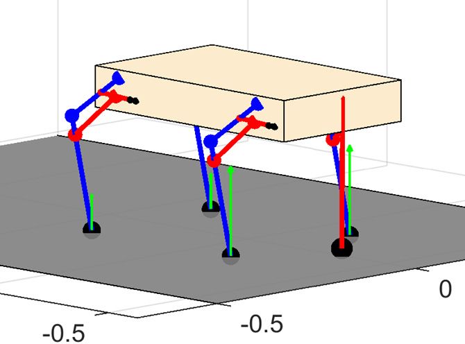
For the new locomotion paradigm, the core task of the tail              airborne dynamics (       ). Stability is also not guaranteed after
system is to balance the quadruped during locomotion so that                 the feet are touching the ground. Moreover, in PFL, limitations
the simplified legs could focus on propelling. Therefore, a                  on the tail range of motion are not applied.
closed-loop tail controller that can automatically adjust the torso
orientation is needed. Considering the high under-actuation                  4.1 Tail Orientation Controller (TOC)
characteristics of the system and the unnecessity of controlling                  When the quadruped is airborne, the control goal is to make
tail position, the input-to-output partial feedback linearization            sure that the robot lands on the ground at a desired orientation.
(PFL) controller [21] is found suitable for this task. The                   Therefore, using the PFL formulation, the TOC is derived by
“partial” here refers to the fact that this formulation only                 setting the state error of the torso roll and pitch as the output
linearizes the selected state dynamics, in this case, the torso              function, i.e.                            where      and the
orientation .                                                                are the desired pitch and roll angles, respectively. As discussed
     Firstly, the desired output is constructed as                           before, is invertible in this case and             . However, in
                                                                             some applications, the locomotion direction (yaw angle) may be
                                                                  (9)
                                                                             also a control objective. For these cases, the output could be
such that the selected states          follows the desired                   chosen as                                   and the least square
trajectory   and         / is the selection matrix, where                    solution                   maybe used to find the generalized
indicates the dimension of       . Then the desired output                   inverse of . As for the one-dimensional output cases (e.g., the
dynamics could be constructed as                                             only motion of interest is rolling), inverse is calculated as
                                                                                              .
                                                                 (10)
where              and                   with ,           0. Solving         4.2 Resting Damping Control (RDC)
for from Eq. (1) and extracting        from yields                                When the quadruped is on the ground and is in a stable
                                                                             position, the active tail motion may not be necessary. For these
                                                                 (11)        situations, the tail controller should simply let the tail go back to
Substituting Eq. (11) into Eq. (10) and solving for             , the        its natural position. Therefore, the RDC is formulated as a
feedback controller is derived as                                            simple pure damping system

                                                                 (12)                                diag                                    (17)
                                                                             where       ,      0 are the damping coefficients. Since this
in which                , and      indicates the Moore-Penrose
                                                                             controller is equivalent to introducing friction into the tail
inverse of .
                                                                             joints, the system maintains its stability after switching to this
    The stability proof of the controller is straightforward.
                                                                             controller. Note that this controller does not use the PFL
Substituting Eq. (12) back into the system dynamics yields
                                                                             formulation derived in the previous sections.
                                                                 (13)
                                                                                                TABLE 1. RCQ parameters
Multiplying             on both sides, Eq. (13) becomes
                                                                                    Para.              Value           Para.        Value
                                                                 (14)                                  12 Kg                      5E4 Nm-1
                                                                                 Torso Length          0.6 m                        0.75
which is further simplified to                                                   Torso Width           0.3 m              ,       3E4 Nm-1
                                                                 (15)            Tail Length        0.45-0.9 m            ,          0.01
                                                                                      p           diag([0.36 0.09
Therefore, if        2 (i.e.  is a square matrix),                                     Ib                                 ,            1
                                                                                                   0.45]) Kgm2
(assuming that    is away from its singularities). Then
                                                                                                       1 Kg                            1
                                                                 (16)
which is known to be exponentially stable (unforced damped                                            9.8 ms-2
harmonic oscillator). However, if          2 (i.e. is not square),
the stability may not be guaranteed. Specifically, if       1,      is
column independent (2 by 1 matrix) such that the null space of               5    SIMULATION
Eq. (15) is the same as Eq. (16). The output is still stable in                   All numerical computations were conducted in Matlab
this case. If     2,     is row independent such that the null               where the built-in function ode45 with 1E-6 relative tolerance
space of Eq. (15) is no more than just a zero vector, which could            and 1E-8 absolute tolerance, was used for numerical integration.
expand to a line or a plane. In this case, the output stability is no        For the PFL controller output dynamics, the differentiation gain
longer guaranteed. Note that the controller is derived based on                  is determined by setting the desired time constant to

                                                                         5                                          Copyright © 2021 by ASME
0.02 seconds so that the output could be zeroed in 5 0.1 5.2 Bounding
seconds (5 guarantees 0.5% error). The proportional gain Using the same setup as the pronking gait, a bounding
was determined by the critical damping condition that reduces simulation is conducted. The time response plots and the pitch
the oscillation. These two conditions yield angle phase portraits are presented in Fig. 6. It can be found
that due to the alternative foot contact, the bounding gait has
2/ 0.02 ⇒ 100 (18) two impact events (two nondifferentiable points in the z plot).
4 0⇒ 2500 (19) The phase portrait is also more chaotic than the pronking gait.
The GRF and the tail controller effort are also computed and
All the RCQ parameters used are collected in Table 1, except presented in Fig. 7 where the “FL” and “FR” stand for the front
for the leg dimensions which can be found in [15]. Tail torque left leg and the front right leg respectively. The “ ” and “ ”
saturation is set to 30Nm. are the two components of , in correspondence to the
joint and the joint of the tail, respectively. From the figure, it
5.1 Pronking can be found that the rolling joint is actually not used due to the
Due to its simplicity, the first set of simulations is for the fact that both the pronking and the bounding are essentially two
pronking gait where the quadruped is released in the air at a gaits in the sagittal plane. It can be also found that the actual tail
height of 0.5 meters and starts acting at 0.3 seconds. The controller uses saturated torque for the orientation re-righting.
simulation lasts 10 seconds and a longer tail (0.9 meters) is used
to achieve more robust performance. Figure 5 shows the
corresponding time response plots and the pitch angle phase
portraits. From the figures, the pronking gait achieves stable
locomotion and the phase portraits evolve in a bounded range.
FIGURE 7. Bounding gait test: GRF and control effort
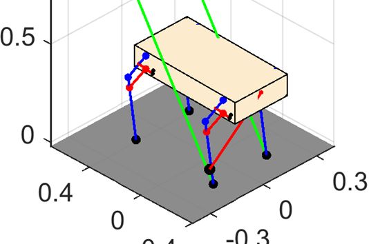
5.3 Maneuvering Case Study
As stated in Section 3.3, the two tail inputs are not able to
FIGURE 5. Pronking gait test: position information and fully control the three objectives in the maneuvering motion.
phase portrait (bottom right) Therefore, only a case study was performed, to observe the
usefulness of the tail on the maneuvering locomotion. Figure 8
shows the snapshots of the maneuvering case study where a
0.45 meters long tail is used without applying torque saturation
and is set to 15 degrees. Due to the least square solution (see
Section 4.1), the tail controller cannot exactly track the desired
control objective, which results in an actual turning angle of
16.45 degrees. This suggests that tails with more inputs should
be used for fully controlling the quadruped orientation.
5.4 Discussion
It is worth noting that for the RCQ, due to the single DOF
leg, if three legs touch the ground at the same time (equivalent
to adding spherical joints between the feet and the ground), the
mobility (the overall DOF) reduces to zero. Therefore, all gaits
requiring three legs touching the ground at the same time
FIGURE 6. Bounding gait test: position information and (except for pronking since the spherical constraints introduced
phase portrait (bottom right) by pronking are redundant constraints) are impossible, e.g.
walking and ambling. With help from the tail, all other gaits,
namely, trotting, pacing, cantering, and galloping, are
6 Copyright © 2021 by ASME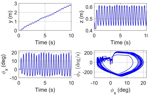
z(m)

     y(m)         x(m)
            0ms            50ms          100ms            150ms               200ms        250ms           300ms            350ms
                                        FIGURE 8. Snapshots for the maneuvering case study

theoretically possible.                                                 [3]  Hutter, M., Gehring, C., Jud, D., Lauber, A., Bellicoso,
     In addition, one main deficiency observed for the current               C.D., Tsounis, V., Hwangbo, J., Bodie, K., Fankhauser,
control strategy was that the tail motion range was not                      P., Bloesch, M., and Diethelm, R., 2016, “Anymal-a
restricted, which is not possible in practice. Therefore, one                Highly Mobile and Dynamic Quadrupedal Robot,”
focus for future work is to modify the tail controller such that             IEEE/RSJ International Conference on Intelligent Robots
the tail motion constraints could be introduced in the controller            and Systems, Daejeon, South Korea, Oct. 9-14, 2016, pp.
design stage, e.g. using numerical optimal control to impose                 38-44.
state constraints in the PFL framework. However, for many               [4] Seok, S., Wang, A., Chuah, M.Y.M., Hyun, D.J., Lee, J.,
applications such as the dynamics-based optimal design, the tail             Otten, D.M., Lang, J.H., and Kim, S., 2014, “Design
controller deficiency may not become a problem because these                 Principles for Energy-Efficient Legged Locomotion and
applications usually only consider the resultant whole robot                 Implementation on the MIT Cheetah Robot,” IEEE/ASME
performance, and the internal tail controller does not affect the            Transactions on Mechatronics, 20(3), pp. 1117-1129.
overall performance due to the conservation of momentum.                [5] Park, H.W., Wensing, P.M., and Kim, S., 2017, “High-
                                                                             speed Bounding with the MIT Cheetah 2: Control Design
6    CONCLUSION                                                              and Experiments,” The International Journal of Robotics
      This paper tackled the dynamic locomotion control                      Research, 36(2), pp. 167-192.
problem of a point-feet reduced complexity quadruped that               [6] Farshidian, F., Jelavic, E., Satapathy, A., Giftthaler, M.,
consists of four single DOF legs and one pendulum tail. Due to               and Buchli, J., 2017, “Real-time Motion Planning of
the special limitations on the legs, a tail is actively used to              Legged Robots: A Model Predictive Control Approach,”
balance the quadruped while the legs are only responsible for                IEEE-RAS 17th International Conference on Humanoid
propelling. To coordinate these two functions, a locomotion                  Robotics, Birmingham, UK, Nov. 15-17, 2017, pp. 577-
control framework that generates leg sequence, leg timing, and               584.
tail controller objective was proposed. The partial feedback            [7] Winkler, A.W., Bellicoso, C.D., Hutter, M., and Buchli, J.,
linearization technique was used to formulate the closed-loop                2018, “Gait and Trajectory Optimization for Legged
tail controller. Due to this special locomotion control strategy,            Systems        Through       Phase-based       End-effector
no trajectory optimization was required. Three sets of numerical             Parameterization,” IEEE Robotics and Automation
experiments including one pronking gait test, one bounding gait              Letters, 3(3), pp. 1560-1567.
test, and one maneuvering case study, were conducted to verify          [8] Patel, A., and Boje, E., 2015, "On the Conical Motion of a
the effectiveness of the tail controller and to evaluate the                 Two-degree-of-freedom Tail Inspired by the Cheetah,"
locomotion controller performance. The results validated the                 IEEE Transactions on Robotics, 31(6), pp. 1555-1560.
proposed control strategy.                                              [9] Libby, T., Moore, T.Y., Chang-Siu, E., Li, D., Cohen,
                                                                             D.J., Jusufi, A., and Full, R.J., 2012, "Tail-assisted Pitch
ACKNOWLEDGMENTS                                                              Control in Lizards, Robots and Dinosaurs," Nature,
    This material is partially based upon work supported by the              481(7380), p. 181.
National Science Foundation under Grant No. 1906727.                    [10] Briggs, R., Lee, J., Haberland, M., and Kim, S., 2012,
                                                                             "Tails in Biomimetic Design: Analysis, Simulation, and
REFERENCES                                                                   Experiment," IEEE/RSJ International Conference on
[1] Raibert, M., Blankespoor, K., Nelson, G., and Playter, R.,               Intelligent Robots and Systems, Vilamoura, Portugal, Oct.
    2008, “Bigdog, the Rough-terrain Quadruped Robot,”                       7-12, 2012, pp. 1473-1480.
    IFAC Proceedings, 41(2), pp. 10822-10825.                           [11] Chang-Siu, E., Libby, T., Brown, M., Full, R.J., and
[2] Semini, C., Tsagarakis, N.G., Guglielmino, E., Focchi, M.,               Tomizuka, M., 2013, “A Nonlinear Feedback Controller
    Cannella, F., and Caldwell, D.G., 2011, “Design of HyQ–                  for Aerial Self-righting by a Tailed Robot,” IEEE
    a Hydraulically and Electrically Actuated Quadruped                      International Conference on Robotics and Automation,
    Robot,” Proceedings of the Institution of Mechanical                     Karlsruhe, Germany, May 6-10, 2013, pp. 32-39.
    Engineers, Part I: Journal of Systems and Control                   [12] Heim, S.W., Ajallooeian, M., Eckert, P., Vespignani, M.,
    Engineering, 225(6), pp. 831-849.                                        and Ijspeert, A.J., 2016, “On Designing an Active Tail for
                                                                             Legged Robots: Simplifying Control via Decoupling of

                                                                    7                                      Copyright © 2021 by ASME
Control Objectives,” Industrial Robot: An International        [17] Liu, Y., and Ben-Tzvi, P., 2021, "Dynamic Modeling,
       Journal, 43(3), pp. 338-346.                                        Analysis, and Comparative Study of a Quadruped with
[13]   Rone, W.S., Liu, Y., and Ben-Tzvi, P., 2019,                        Bio-inspired Robotic Tails," Multibody System Dynamics,
       “Maneuvering and Stabilization Control of a Bipedal                 51(2), pp. 195–219.
       Robot with a Universal-spatial Robotic Tail,”                  [18] Mistry, M., Buchli, J., and Schaal, S., 2010, “Inverse
       Bioinspiration & Biomimetics, 14(1), p. 016014.                     Dynamics Control of Floating Base Systems using
[14]   Saab, W., Yang, J., and Ben-Tzvi, P., 2018, “Modeling               Orthogonal     Decomposition,”      IEEE    International
       and Control of an Articulated Tail for Maneuvering a                Conference on Robotics and Automation, Anchorage, AK,
       Reduced Degree of Freedom Legged Robot,” IEEE/RSJ                   USA, May 3-7, 2010, pp. 3406-3412.
       International Conference on Intelligent Robots and             [19] Hurmuzlu, Y., GéNot, F., and Brogliato, B., 2004,
       Systems, Madrid, Spain, Oct. 1–5, 2018, pp. 2695-2700.              “Modeling, Stability and Control of Biped Robots—a
[15]   Liu, Y., and Ben-Tzvi, P., 2020, “An Articulated Closed             General Framework,” Automatica, 40(10), pp. 1647-1664.
       Kinematic Chain Planar Robotic Leg for High Speed              [20] Azad, M., and Featherstone, R., 2014, “A New Nonlinear
       Locomotion,” Journal of Mechanisms and Robotics,                    Model of Contact Normal Force,” IEEE Transactions on
       12(4), p. 041003.                                                   Robotics, 30(3), pp. 736-739.
[16]   Grizzle, J.W., Chevallereau, C., Sinnet, R.W., and Ames,       [21] Spong, M.W., 1994, “Partial Feedback Linearization of
       A.D., 2014, “Models, Feedback Control, and Open                     Underactuated      Mechanical     Systems,”    IEEE/RSJ
       Problems of 3D Bipedal Robotic Walking,” Automatica,                International Conference on Intelligent Robots and
       50(8), pp. 1955-1988.                                               Systems, Munich, Germany, Sep. 12-16, 1994, pp. 314-
                                                                           321.

                                                                  8                                     Copyright © 2021 by ASME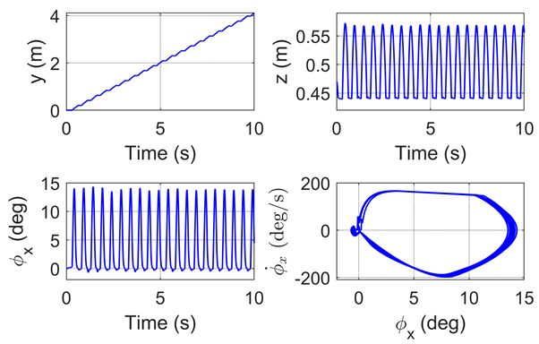
You can also read