Development of Separate Sensible and Latent Cooling System Using Electrochemical Compressor - Xergy Inc.
←
→
Page content transcription
If your browser does not render page correctly, please read the page content below
Development of Separate Sensible and Latent Cooling System
 Using Electrochemical Compressor
Omar Abdelaziza, Qu Minga, Xiaoguang Suna, Bamdad Baharb*, William Parmeleeb,
 Scott Facklerb, Richard Sherrerb, Jacob Zerbyb, Ashish Chouhanc, Ajay Prasadc
 a
 Oak Ridge National Laboratory, One Bethel Valley Rd.,Oak Ridge, TN 37831-6070, U.S.A
 b
 Xergy Inc, 105 Park Ave, Seaford, Delaware 19973, U.S.A
 c
 University of Delaware, Newark, DE 19716-3140, U.S.A.

Abstract

 Separate sensible and latent cooling systems offer superior energy efficiency performance compared to
conventional vapor compression air conditioning systems. In this paper we describe an innovative non-vapor
compression system that uses electrochemical compressor (ECC) to pump hydrogen between 2-metal hydride
reservoirs to provide the sensible cooling effect. The heat rejected during this process is used to regenerate the
ionic liquid (IL) used for desiccant dehumidification. The overall system design is illustrated. The Xergy
version 4C electrochemical compressor, while not designed as a high pressure system, develops in excess of 2
MPa (300 psia) and pressure ratios > 30. The projected base efficiency improvement of the electrochemical
compressor is expected to be ~ 20% with higher efficiency when in low capacity mode due to being throttleable
to lower capacity with improved efficiency. The IL was tailored to maximize the absorption/desorption rate of
water vapor at moderate regeneration temperature. This IL, namely, [EMIm].OAc, is a hydrophilic IL with a
working concentration range of 28.98% when operating between 25 – 75 °C. The ECC metal hydride system is
expected to show superior performance to typical vapor compression systems. As such, the combined
efficiency gains from the use of ECC and separate and sensible cooling would offer significant potential
savings to existing vapor compression cooling technology. A high efficiency Window Air Conditioner system
is described based on this novel configuration. The system’s schematic is provided. Models compared well
with actual operating data obtained by running the prototype system. Finally, a model of an LiCl desiccant
system in conjunction with the ECC-based metal hydride heat exchangers is provided.

© 2017 Stichting HPC 2017.
Selection and/or peer-review under responsibility of the organizers of the 12th IEA Heat Pump Conference 2017.

Keywords: electrochemical compressor; separate sensible and latent; ionic liquid; high efficiency; window air conditioner.

This manuscript has been authored by UT-Battelle, LLC under Contract No. DE-AC05-00OR22725 with the U.S. Department of Energy.
The United States Government retains and the publisher, by accepting the article for publication, acknowledges that the United States
Government retains a non-exclusive, paid-up, irrevocable, worldwide license to publish or reproduce the published form of this
manuscript, or allow others to do so, for United States Government purposes. The Department of Energy will provide public access to
these results of federally sponsored research in accordance with the DOE Public Access Plan (http://energy.gov/downloads/doe-public-
access-plan).
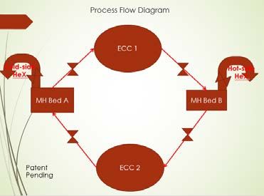
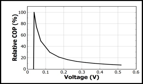
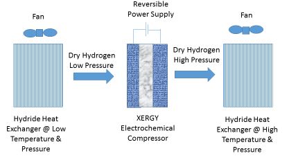
Author name / 12th IEA Heat Pump Conference00 (2017) 000–000

1. Introduction

 Heat pumps employing electrochemical compressors are a transformative and disruptive platform
technology. Electrochemical compression can serve as a basis for heat pumps in different ways; in virtually all
cases, ECC’s show high operating efficiencies and other benefits such as noiseless operation, and the ability to
operate without the use of Global Warming Potential (GWP) working fluids [1-3]. It is also important to
recognize that mechanical compressors, an incumbent technology with over 100 years of refinement, supports a
multibillion dollar global industry which has consistently improved the performance of these units’ year after
year, with large engineering and development teams. This paper explores the application of electrochemical
compressors for use in window air conditioning systems. The work has been supported by the Department of
Energy (DOE)’s BENEFIT program [4]. The program has the following 3 goals:
 • Achieve a COP > 4
 • Achieve an incremental installed price premium < $ 70/kBTU (when manufactured at scale)
 • Set up a high-volume supply chain to be able to provide low cost components to meet commercial
 unit targets

2. System Components

 The novel system configuration employs the following unique features: an electrochemical compressor, 2
metal-hydride heat exchangers, and the liquid desiccant latent cooling subsystem. Below are detailed
descriptions of the different system components.

2.1. Electrochemical compressors

 Electrochemical Compressors (ECC) can employ many different working fluids and thermodynamic cycles.
In their simplest form, the compressors can compress hydrogen, via proton pumping. With hydrogen as the
working fluid, an electrochemical hydrogen compressor is supplied with hydrogen to the anode, and
compressed hydrogen is generated at the cathode. When operated at low ‘voltages’, ECCs provide very high
compression efficiencies (Fig. 1). In one configuration, these compressors can be combined with metal hydride
heat exchangers to provide heating and cooling as shown in (Fig. 2).

 Fig. 1. ECC relative COP (COP/COPCarnot) at various cell voltage

 2

Author name / 12th IEA Heat Pump Conference00 (2017) 000–000

 Fig. 2. ECC combined with metal hydride heat exchangers

2.2. Metal Hydride Heat Exchangers

 Metal hydrides are metallic compounds, in which one or more hydrogen centers have nucleophilic, reducing,
or basic properties. For heat pumps, we utilize the reversible heat-driven reaction of a hydride-forming
metal/alloy, or intermetallic compound (IMC) with hydrogen gas:

 ( ) + 2 ( ) ⇄ ( ) + (1)
 2

 In Eq.1, M is a metal or alloy (e.g., V or a BCC solid solution based upon it), or an IMC (AB5, AB2, etc.);
(s) and (g) relate to solid and gas phases, respectively, and Q is the reaction enthalpy. The overall process
performance is strongly dependent on the intrinsic features of metal hydride reaction including its
thermodynamic and kinetic characteristics, as well as composition, structure and morphology of the solid
phases (M, MHx) involved in the process. These features are mainly related to fundamental aspects of hydride
materials. For a given compressor operating voltage (eg .05v/cell) system efficiency (COP) is linearly related to
the enthalpy of adsorption varying from 2 to 8 for hydride enthalpy of absorptions of 20 to 80 kJ/mole H2.

 Equilibrium of the metal hydride reaction is characterized by an interrelation between hydrogen pressure
(P), concentration of hydrogen in the solid phase (C) and temperature (T). PCT diagrams can be generated to
characterize specific hydride-forming materials. These provide the thermodynamics of its interaction with
gaseous hydrogen. At low hydrogen concentrations (0 ≤ C < a) hydrogen atoms form an interstitial solid
solution in the matrix per Henry–Sieverts law. When the value of C exceeds concentration of the saturated solid
solution, precipitation of the hydride (β-phase with hydrogen concentration) occurs. The system then exhibits a
first order phase transition at a constant hydrogen pressure, P = PP (a ≤ C ≤ b). This pressure is called the
plateau pressure in the metal–hydrogen systems. The process is almost exactly (100%) reversible, with slight
differences as the concentration changes. This is termed hysteresis, and is a source of efficiency loss (
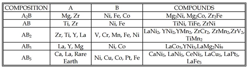
Author name / 12th IEA Heat Pump Conference00 (2017) 000–000

while significantly higher, >1 kbar, hydrogen pressures can be generated using AB2-type compounds. Indeed,
the AB2 compounds have significantly higher enthalpy of adsorption and higher percentage hydrogen storage
capacity, see Fig.3. Xergy has built systems with a wide range of commercial AB5 compounds. With AB2
compounds, a much higher thermal exchange capacity is feasible which would lead to smaller heat exchangers.

Fig. 3. Hydride and non-hydride forming elements in the periodic system of elements (top) and typical examples of intermetallic hydrides
 (bottom)[5].

 Proper hydride selection is critical to designing useful metal hydride heat exchangers. For durable
performance, hydride systems must remain dry. ECC-driven hydride heat exchangers are dual modular systems.
A schematic of a potential ECC-based Metal Hydride heat Exchanger (MHX) system is shown in Fig. 3a. Fig.
3b shows a prototype picture of a system with air heat exchangers. In Fig. 4a when using membranes that
require hydration to function, the valves would be an appropriately controlled parallel system for (1) water
removal and (2) water addition to the hydrogen stream, i.e. a desiccant bed for hydrogen pumped toward the
hydride bed and a humidifier for the hydrogen gas being pulled from the hydride bed. The system can also be
reduced to one ECC by appropriate plumbing and three-way valves.

 Xergy first pioneered the concept of an electrochemical compressor driven metal hydride system in 2014,
and the concept was demonstrated in collaboration with a team sponsored by Xergy at the University of
Delaware (U.D.). This work resulted in a publication by Fornari et al, in November 2014 at U.D. Since then
Xergy has built several advanced ECC-driven heat pumps and filed a family of patents based on this
technology.

 4
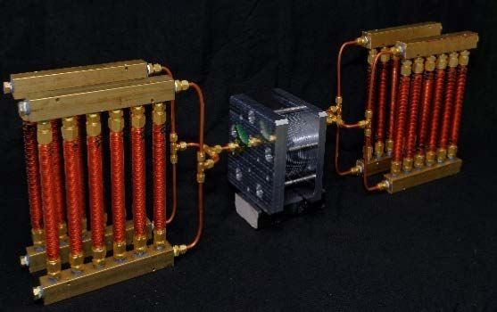
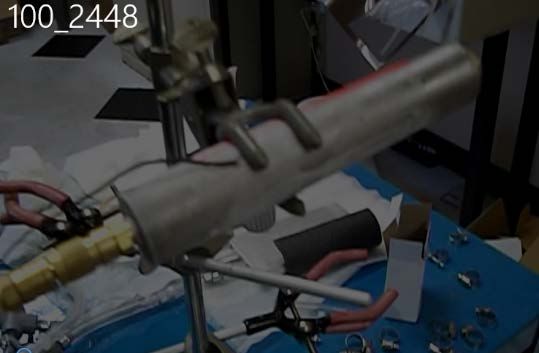
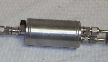
Author name / 12th IEA Heat Pump Conference00 (2017) 000–000

 Fig. 4. (a) A schematic for a potential ECC-based MHX. (b) Picture of prototype ECC-based MHX built by Xergy.

 Initial development of the electrochemical compressor-based metal hydride system was conducted with
commercially available hydride cylinders with heat exchanger capability. Two designs differing in the
placement of the heat exchanger coil and the aspect ratio of the units were tested: (1) exterior-wrapped tubes
brazed to the high aspect-ratio hydride containing cylinder (Fig.5a), and (2) a coiled tube placed inside a lower
aspect ratio hydride cylinder (Fig. 5b). Both designs showed significant deficiencies in heat exchange
capability. It is critical that good heat transport be achieved in order to eliminate hot or cold spots while the
hydride is sorbing/desorbing. On desorbing/sorbing H2 the heat exchanger gets very cold, -7.8°C (18°F), and
hot, 86.1°C (187°F), with materials we expect to use in the basic heat exchanger. We can employ more
expensive and less common materials for special very cold or very hot sink and source requirements and for
enhanced COP (higher enthalpy variants).

 As discussed earlier, the ECC-MHX consists of one or 2 ECC and 2 beds of MHX with associate valves and
control equipment. In the initial configuration that was investigated, the ECC pumped the hydrogen from MHX
bed A, thereby reducing its temperature and pressure, to MHX bed b, were H2 is being adsorbed resulting in
significant heat release. A heat exchanger between bed A and the room allows the bed A to provide the cooling
effect and another heat exchanger between bed B and water allows bed B to reject heat to the high temperature
reservoir. When the desorbing bed A pressure drops to the point that the hydrogen compressor shows signs of
insufficient hydrogen supply (approximately 138 kPa (20 PSIG)) all the valves are switched to the opposite
sense. Hydride bed B is now connected to the suction side of the ECC and accepts heat from the room air heat
exchanger, while hydride bed A is now absorbing hydrogen while dumping heat to the water tank.

 Fig. 5. Hydride cylinders with heat exchanger capability (a) high aspect-ratio hydride with potential for exterior wrap-around coil and (b)
 (b) a coiled tube placed inside a lower aspect ratio hydride cylinder.
 5
Author name / 12th IEA Heat Pump Conference00 (2017) 000–000

 Fig. 6 shows results for COP vs operating voltage. “G” represents the case for higher COP at low voltages
and currents (H2 flow) for steady state maintenance of temperature. Subsequently, we targeted faster heating
by operating at higher voltages represented by “T”. The calculated COPs, G=2.8 and T=1.4, are very close to
the expected values based on the model.

 Fig. 6. ECC-MHX Heat Pump Water Heater COP (heating COP) as a function of voltage.

2.3. Liquid Desiccant Subsystem

 Air conditioning is used to control both the temperature and the humidity of indoor air to provide the
preferred level of thermal comfort. In warm and humid climates, the latent load charged by a dehumidifier for
moisture removal could represent up to 88% of the total air conditioning load according to Harriman III [6].
Therefore, air dehumidification can be an energy-intensive process. Liquid desiccant air conditioning (LDAC)
has been investigated as a promising alternative to vapor compression (VC) technology because it has lower
electricity consumption, a higher system coefficient of performance (COP), a reduced condensate air flow rate,
and a reduced VC size [7-14]. LDAC separates the sensible cooling and latent cooling to meet the requirements
of humidity and temperature independently. LDAC uses the liquid desiccant to absorb the moisture in the air
driven by the difference between the vapor pressure at the surface of the liquid desiccant and that of the
surrounding air in order to eliminate the electrical demand of the VC system used for the dehumidification.

 In our design, we use the ECC-MHX to provide the sensible cooling and the liquid desiccant susbsystem
provides the latent cooling. The systems are to be designed such that the waste heat from the ECC-MHX be
used as the heat source to regenerate the deiccant solution. The liquid desiccant subsystem consists of 2 heat
and mass exchangers (dehumifier and regenerator) and 4 heat exchangers (solution cooler, solution heater,
internal heat exchanger, and air heat recovery). The solution heater and cooler can be combined with the
regenerator and dehumifier respectively to reduce cost. The internal heat excanger is important to minimize
internal heat loss and maintain high efficiency and the ambient air heat recovery heat exchanger can be made of
low cost polymer materials to reduce cost. Fig. 7 below shows a schematic of a possible configuration of the
liquid desiccant subsystem integrated with the ECC-MHX. In this design, the sensible cooler is cooled by the
ECC-MHX and the solution heater is heated by the waste heat of the ECC-MHX.

 6
Author name / 12th IEA Heat Pump Conference00 (2017) 000–000

 Exhaust Air
 80% RA + 20% OA
 Dehumidifier

 Regenerator
 Internal HX
 Solution Outdoor Air
 Cooler Solution Heater
 Sensible
 Cooler

 ECC-MHX

 Supply Air

 Fig. 7. Schematic of a system configuration of separate sensible and latent cooling employing liquid desiccant subsystem

 The case study of the system design in this paper was for a 5.4 kW (18,000 Btu/hr) system with 0.189 m3/s
(400 cfm) air volume operated at standard AHRI rating conditions. Twenty percent (80 cfm) of the total air
volume was from outdoor air (OA) and was mixed with the 80% return room air (RA) from the space. In a
typical vapor compression system, the mixed air (MA) should be cooled down to the dry bulb temperature at
12.78°C (55°F) with the wet temperature at 12.2 °C (54°F), which represents a 0.68 sensible heating ratio
(SHR). The total cooling load is approximately 5.4 kW (1.54 cooling tons) while the vapor compression system
required 5.856 kW to meet the same load due to the overcooling and reheating process. To provide the same
amount of cooling at 5.4 kW, the LDAC system can supply air at the same condition as the typical system or at
a higher temperature at 18.3°C (65°F) with relative humidity at 65.8%, if the air volume flow rate is increased
to 0.25m3/s (528 cfm).

2.3.1. Ionic Liquid

 Historically ordinary (hydroscopic) salts such as NaCl, LiCl, LiBr have been used in HVAC applications as
liquid desiccants. Ionic liquids, which are salts comprised of organic cations and inorganic anions or organic
anions, become liquid when exposed to room temperature and atmospheric pressure. They have high thermal
stability, negligible or no vapor pressure, varied solubility in water, low or no corrosion to metals, and low
driving temperatures to achieve dew point temperatures. ILs, therefore, can be used as desiccant materials to
remove humidity from environment. A few research groups investigated ILs as potential alternatives to
 7
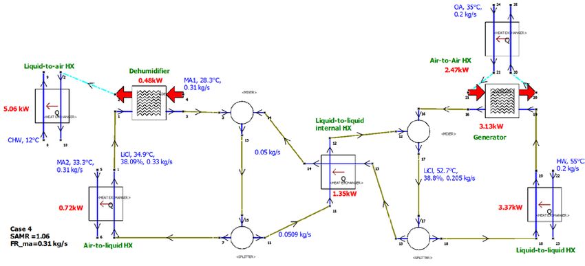
Author name / 12th IEA Heat Pump Conference00 (2017) 000–000

traditional desiccant liquids used in LDAC [15-17]. There are in fact, bulky, asymmetric organic cations that
provide better performance than traditional salt solution in HVAC applications. Organic salts can also be
tailored and optimized for specific operating conditions. There are very few other publications available about
the ILs used as desiccant liquids. We synthesized 13 different ILs, and performed absorption & desorption
evaluations for these candidates. All tests were performed under thermodynamic equilibrium conditions. The
objective of the research was to identify an ideal substitute for traditional desiccant liquids among the identified
ILs that have good thermal stability, high solubility in water, low or no corrosion to metals, and potential for
low cost when manufactured at scale and system performance for the applications of LDAC. First, screening
tests were conducted with all 13 candidates for identifying the most promising candidate(s) that can provide the
highest vapor adsorption and desorption. Among the 13 different ILs, 1-Ethyl-3-methylimidazolium acetate
exhibited the highest capability of absorbing vapor and desorbing water and was identified as the most
promising substitute. Its molecular formula is C8H14N2O2 and its molar-mass is 170.21 g/mol. It can be
abbreviated as [EMIM][OAc] / [emim][OAc] or [C2MIm][OAc].
 A large number of studies were found in the literature that investigated the properties of pure [EMIM][OAc]
or the solution with little water [18-23]; however, only a few addressed the properties for the aqueous solution
of 1-Ethyl-3-methylimidazolium acetate [24]. Based on the literatures, we summarized the data of the thermos-
physical properties for the aqueous solution of [EMIM][OAc] and generated the calculation formulations for
predicting the thermos-physical properties of the aqueous solution of [EMIM][OAc] by using both
thermodynamic principles and statistical methods. The calculation formulations were generated to predict the
following thermos-physical properties of the aqueous solution of [EMIM][OAc]:vapor pressures, specific heat
capacity, density, and dynamic viscosity.

2.3.2. Results of Liquid Desiccant Subsystem

 For our system study and analysis, we used LiCl aqueous solutions as the working fluid in order to make
sure we have reliable fluid data for our simulations. After careful study of several components size impact and
potential cycle modifications to enhance performance, we concluded that the best system configuration is that
shown in Fig. 8. The system consists of seven heat exchangers: two liquid-to-liquid HXs, two air-to-liquid
HXs, one air-to-air HX, one liquid desiccant dehumidifier, and one liquid desiccant generator. In this system,
MA1 = MA2 = 0.31 kg/s (528 cfm). However, MA1 has 80% RA and 20% OA while MA2 has 20% RA and
80% OA. MA1 is the air flow that goes through the dehumidifier, the sensible cooler and eventually provides
the space cooling. MA2 is the air flow used for solution cooling. Another 0.2 kg/s of OA are used for the
generator from the entering air-to-air heat recovery HX. Hot water at 54°C (129°F) from ECC-MHX waste heat
is used to heat the liquid in the liquid-liquid HX. The chilled water at 12°C (54°F) from the ECC-MHX is used
to cool the dehumidified air to the desired temperature of 18.3°C (65°F). The air in the dehumidification
process is very close to an adiabatic process. The heat gain during dehumidification is only about 0.48 kW. The
temperature, flow rate, and concentration of each stream for the dehumidifier and regenerator are summarized
in Tables 1 and 2. The heat exchanger capacity for the system components is summarized in Table 3. The
LDAC system shown in Fig. 8 only required 5.06 kW of sensible cooling at 12°C compared to the VC system.

 8
Author name / 12th IEA Heat Pump Conference00 (2017) 000–000

 Fig. 7. Hydride cylinders with heat exchanger capability (a) high aspect-ratio hydride with potential for exterior wrap-around coil and (b)
 (b) a coiled tube placed inside a lower aspect ratio hydride cylinder.

Table 1 Dehumidifier performance assuming NTU = 2.2
 Variable Value Unit
 Solution inlet temperature 34.88 °C
 Solution outlet temperature 35.51 °C
 Solution flow rate 0.33 kg/s
 Solution inlet concentration 38.08 %
 Solution outlet concentration 37.97 %
 Air inlet temperature 28.3 °C
 Air outlet temperature 34.28 °C
 Air flow rate 0.31 kg/s
 Air inlet humidity ratio 0.0116 kg/kgdry air
 Air outlet humidity ratio 0.0086 kg/kgdry air

Table 2 Regenerator performance assuming NTU = 2.2
 Variable Value Unit
 Solution inlet temperature 52.76 °C
 Solution outlet temperature 46.99 °C
 Solution flow rate 0.2 kg/s
 Solution inlet concentration 38.79 %
 Solution outlet concentration 38.97 %
 Air inlet temperature 46.93 °C
 Air outlet temperature 50.41 °C
 Air flow rate 0.2 kg/s
 Air inlet humidity ratio 0.0142 kg/kgdry air
 Air outlet humidity ratio 0.0189 kg/kgdry air
 9
Author name / 12th IEA Heat Pump Conference00 (2017) 000–000

Table 3 Heat exchangers duty
 Heat Exchanger Duty, kW
 Dehumidifier 0.48
 Regenerator -3.13
 Internal heat exchanger 1.34
 Solution cooler 0.72
 Solution heater 3.38
 Outdoor heat recovery 2.46
 Sensible cooler 5.06

3. Overall System Result

 This study used an electrochemical compressor to produce chilled water at; and the heat generated during
electrochemical compression was used as the heating source in the generation loop. Therefore, electricity was
consumed only to compare the recommended LDAC system to the conventional VCR. The COP of the
electrochemical compressor for producing chilled water at 12°C (54°F) was assumed to be 5. Therefore, the
total electricity demand for generating 5.06 kW chilled water at 12°C (54°F) was 1.02 kW of electric power.
Comparably, if a VCR system was used to provide the 5.4 kW of cooling, as discussed in earlier, the electricity
demand was 1.677 kW to provide 5.856 kW of total cooling and moisture removal by using 3.5 as the COP
(EER = 12) of typical VC system. In addition, the power to be used for the fans and pumps in LDAC which are
additional to those used in a typical VCR shall be included in the system performance analysis. The
recommended LDAC system primarily consists of two fans for the dehumidifier and the regenerator, and two
pumps in the dehumidification and regeneration loops. The fan for the regenerator and the two pumps are
assumed as the devices in the LDAC additional to those in the VC system. According to ASHRAE/IES
Standard 90.1-2013, fan power rate is 365 W/1000 cfm. To provide a 0.2 kg/s (340 cfm) air flow, the fan power
is 0.124 kW. According to ASHRAE 90.1, pump power rate is 22 W/gpm. To provide a 0.33 kg/s (5.23 gpm)
of water flow in the dehumidification loop and a 0.21 kg/s (3.33 gpm) of water flow in the regeneration loop,
the total pump power is 0.188 kW. As such, the overall energy consumption for the LDAC/ECC-MHX would
be 1.332 kW; and the expected energy savings compared to best in class window unit (EER 12) is 21%.

4. Conclusions

 A basic framework for a highly efficient, noiseless, vibration free heat pump system without GWP working
fluids, and utilizing liquid desiccant to avoid latent heat loads has been provided for a window air conditioner.
This concept can clearly serve as a basis for larger heating and cooling applications – where the savings can be
significantly larger.

 The study presented in this paper identified a system configuration for LDAC coupled with electrochemical
compression. The rationale and the process of identifying the system configuration were discussed and
illustrated. Five cases of different system configurations were studied and simulated in Sorpsim. The final
recommended system configuration was determined based on its 21% energy savings compared to a
conventional VC system. The findings in this paper will be the foundation for the upcoming next phase of this
study, which includes prototype design, fabrication, testing, and analysis.

 10
Author name / 12th IEA Heat Pump Conference00 (2017) 000–000

Acknowledgements

 This research was supported by the U.S. Department of Energy Office of Building Technologies, BENEFIT
program.

References

[1] HFCs: A Critical Link in Protecting Climate and the Ozone Layer retrieved from
 http://www.unep.org/publications/ebooks/hfc-report/
[2] Fortems-Cheiney, A., M. Saunois, I. Pison, F. Chevallier, P. Bousquet, C. Cressot, S. A. Montzka, P. J.
 Fraser, M. K. Vollmer, P. G. Simmonds, et al. (2015), Increase in HFC-134a emissions in response to the
 success of the Montreal Protocol, J. Geophys. Res. Atmos., 120, 11,728–11,742,
 doi:10.1002/2015JD023741.
[3] Bloomfield, D. P., June 10, 1986, Electrochemically driven heat pump, U.S 4,593,534
[4] BEETIT_ProgramOverview.pdf https://arpa-
 e.energy.gov/sites/default/files/documents/files/BEETIT_ProgramOverview.pdf
[5] Dornheim, M., Thermodynamics of Metal Hydrides: Tailoring Reaction Enthalpies of Hydrogen Storage
 Materials, 2011, Thermodynamics - Interaction Studies - Solids, Liquids and Gases, Dr. Juan Carlos
 Moreno Piraján (Ed.), InTech, DOI: 10.5772/21662. Available from:
 http://www.intechopen.com/books/thermodynamics-interaction-studies-solids-liquids-and-
 gases/thermodynamics-of-metal-hydrides-tailoring-reaction-enthalpies-of-hydrogen-storage-materials
[6] Harriman III, L. G., Plager, D. and Kosar. D., Dehumidification and cooling loads from ventilation air."
 ASHRAE Journal, pp. 37–45, 1997.
[7] Dai, Y. Wang, R. Zhang, H. and Yu, J., Use of liquid desiccant cooling to improve the performance of
 vapor compression air conditioning, Applied Thermal Engineering, Vol. 21, pp. 1185-1202, 2001.
[8] Rafique, M. M. Gandhidasan, P.and Haitham, M. B., Liquid desiccant materials and dehumidifiers – A
 review. Renewable and Sustainnable Energy Reviews, No. 56, pp. 179-195, 2016.
[9] Lowenstein, A., Review of liquid desiccant technology for HVAC applications, HVACR Res.14 (2008)
 819–839.
[10] T.M. Abdulrahman, B.M. Sohif, M. Sulaiman, K. Sopian, and A.A. Abduljalil, Review: Survey of the
 control strategy of liquid desiccant systems, Renewable and Sustainable Energy Reviews 58 (2016) 250-
 258.
[11] Waugaman, D.G. Kini, A. Kettleborough, C.F., A review of desiccant cooling systems, Journal of Energy
 Resources Technology 115, no. 1 (1993) 1–8.
[12] Fumo, N. and Goswami, D., Study of an aqueous lithium chloride desiccant system: air dehumidification
 and desiccant regeneration, Solar Energy, Vol. 72, No. 4, pp. 351-361, 2002.
[13] Stevens, D. Braun, J. E. and Klein, S. A., An effectiveness model of liquid desiccant system heat/mass
 exchangers. Solar Energy, Vol. 42, No. 6, pp. 449-455, 1989.
[14] Liu, X. Yi, X., and Jiang, Y., Effect of regeneration mode on the performance of liquid desiccant packed
 bed regenerator, Renewable Energy, Vol. 34, No. 1, pp. 209-216, 2009.
[15] Luo, Y. M., Shao, S. Q., Qin, F., and Tian, C. Q., Investigation on feasibility of ionic liquids used in solar
 liquid desiccant air conditioning system, Solar Energy, 86 no. 9 (2012) 2718- 2724.
[16] Zegenhagen, M. T. Ricart, C. Meyer, T. Kühn, R., and Ziegler, F., Experimental Investigation of A
 Liquid Desiccant System for Air Dehumidification Working With Ionic Liquids, Energy Procedia 70
 (2015) 544-551.
[17] Kudasheva, A. Kamiya, T. Hirota, Y., and Ito, A., Dehumidification of air using liquid membranes with
 ionic liquids, Journal of Membrane Science 499 (2016) 379-385.
 11
Author name / 12th IEA Heat Pump Conference00 (2017) 000–000

[18] Ma, X. X., Li, L., Wei, J., Duan, W. B., Guan, W., and Yang, J. Z., Study on Enthalpy and Molar Heat
 Capacity of Solution for the Ionic Liquid [C2mim][OAc] (1-Ethyl-3-methylimidazolium acetate), Journal
 of Chemical & Engineering Data, 57 no. 11 (2012 ) pp. 3171-3175.
[19] Ahmadi, A., Haghbakhsh, R., Raeissi, S., and Hemmati, V., A simple group contribution correlation for
 the prediction of ionic liquid heat capacities at different temperatures, Fluid Phase Equilibria, 403 no. 15
 (2015) 95-103.
[20] Freire, M.G., Thermophysical Characterization of Ionic Liquids Able To Dissolve Biomass, Journal of
 Chemical & Engineering Data 56, no. 12 (2011) 4813-4822.
[21] Niazi, A. A. , Rabideau, B. D., and Ismail, A. E., Effects of Water Concentration on the Structural and
 Diffusion Properties of Imidazolium-Based Ionic Liquid–Water Mixtures, The Journal of Physical
 Chemistry B 117, no. 5 (2013) 1378-1388.
[22] Radhi, A., Le, K. A., Ries, M. E., and Budtova, T., Macroscopic and Microscopic Study of 1-Ethyl-3-
 methyl-imidazolium Acetate−DMSO Mixtures, The Journal of Physical Chemistry B 119, no. 4 (2015)
 1633-1640.
[23] Almeida, H. F. D., Passos, H., Lopes-da-Silva, J. A., Fernandes, A. M., Freire, M. G., and Coutinho, J. A.
 P., Thermophysical Properties of Five Acetate-Based Ionic Liquids, Journal of Chemical & Engineering
 Data 57, no. 11 (2012) 3005-3013
[24] Römich, C., Merkel, N., Valbonesi, A., Schaber, K., and Sauer, S., Thermodynamic Properties of Binary
 Mixtures of Water and Room-Temperature Ionic Liquids: Vapor Pressures, Heat Capacities, Densities, and
 Viscosities of Water + 1-Ethyl-3-methylimidazolium Acetate and Water+ Diethylmethylammonium
 Methane Sulfonate, J. Chem. Eng. Data, 57, no. 8 (2012) 2258-2264.

 12
You can also read