Dilatometer Series DIL 402 Expedis Select and Supreme - Method, Instruments, Applications
←
→
Page content transcription
If your browser does not render page correctly, please read the page content below
Dilatometer Series
DIL 402 Expedis Select and Supreme
Method, Instruments, Applications
Dilatometry

2
The Method for Determination of Dimensional Changes
Each time a material is exposed to temperature changes – it shows a variation in its dimension.
Whether it is in the course of its regular thermal expansion, by passing a phase transition or
while it undergoes sintering, the substance will either be shrunk or elongated.
Dilatometry is the method of choice to study length change phenomena of ceramics, glasses,
metals, composites, and polymers as well as other construction materials, thus revealing infor-
mation regarding their thermal behavior and about process parameters or sintering (and
curing) kinetics.
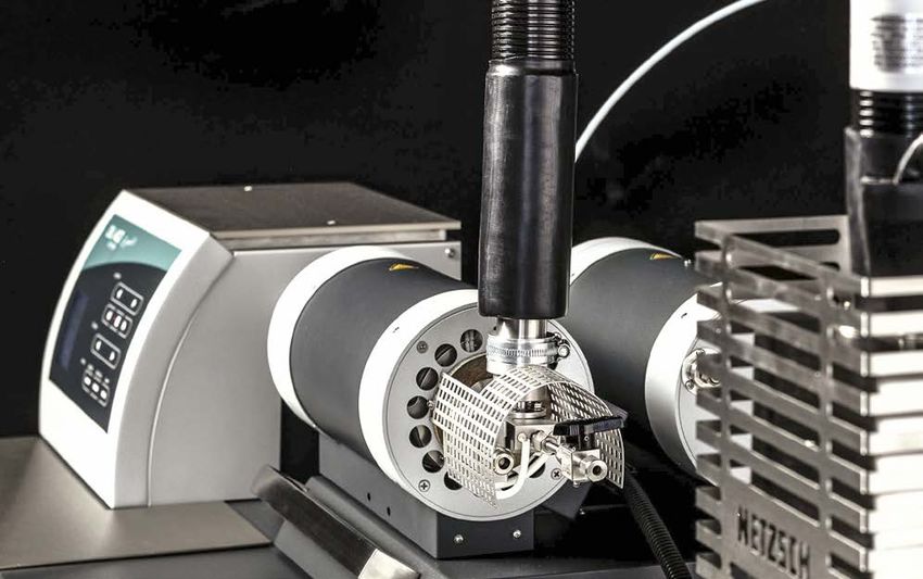
For preparing a dilatometer measurement, the defined sample is inserted into a sample holder
and brought into contact with the pushrod. After closing the furnace, the experiment can be
started.
Thermal expansion of the sample during heating is detected by the displacement system
which the pushrod is connected to.
Results obtainable
by DIL measurements
∙∙∙∙ Linear thermal expansion
Coefficient of thermal
∙∙∙∙
expansion (CTE)
Volumetric expansion
∙∙∙∙
Shrinkage steps
Softening point
∙∙∙∙
Moisture expansion
Glass transition temperature
∙∙∙∙
Phase transitions
Sintering temperature and step
∙∙
Density change
Influence of additives and raw
∙∙
materials
Decomposition temperature
∙∙∙∙
of e.g., organic binders
Anisotropic behavior
∙∙∙∙
Optimizing of firing process
Caloric effects by using c-DTA®
Displacement System
∙∙
Rate-Controlled Sintering (RCS)
Sample Holder Thermokinetics
Furnace
Pushrod
Sample
3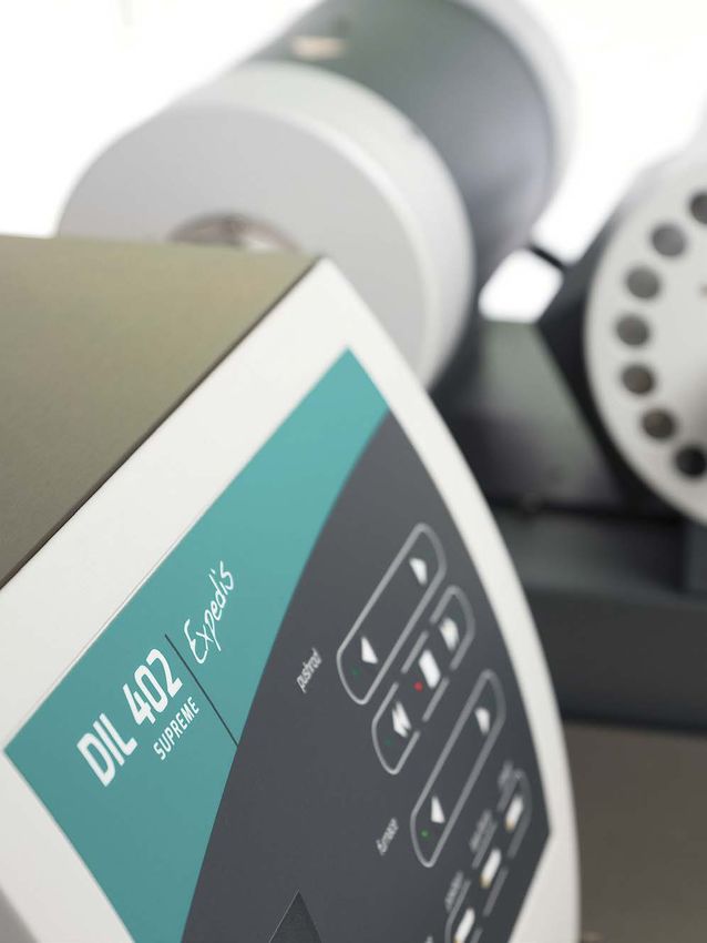
Dilatometry Redefined

    MAXIMUM                                                     UTMOST
    FLEXIBILITY   The double furnace sliding carrier         VERSATILITY   Due to the wide dynamic range
                  creates the opportunity to cover the                     of the measurement system, it
                  entire temperature range from -180°C                     is possible to measure both soft
                  to 2000°C or, alternatively, to increase                 and hard samples without
                  the sample throughput by having two                      impairment of the properties.
                  furnaces available for use.                              Additionally, it enables force
                                                                           modulation and builds a bridge
                                                                           to thermo-mechanical analysis
                                                                           (TMA).

4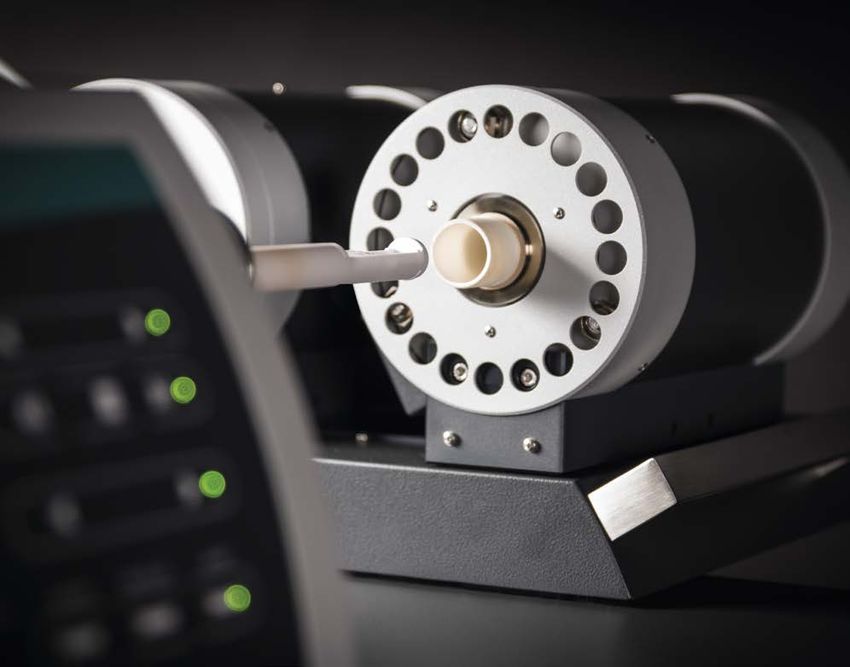
NanoEye – LARGEST MEASURING
  RANGE, HIGHEST RESOLUTION
                 The new, pioneering opto-electronical
                 NanoEye displacement system features
                 perfect linearity and maximum resolution
                 over a measuring range which was
                 impossible to realize until now.

  Instrument
               Resolution         Measuring Range
     Type

    Select        1 nm                ± 10 mm)
   Supreme       0.1 nm                ± 25 mm

USER-OPTIMIZED
        DESIGN   A wide force range for more fragile
                 samples, built-in mass flow controllers
                 and electrical thermostatting of the
                 measuring cell to suppress any temper-
                 ature influence from the surrounding
                 provide for ease-of-use and maximum
                 operational safety.

                                                            55
NanoEye
                         A New Dimension in Measuring Range and Accuracy

                       In classical dilatometry, the two parameters measurement range and resolution
                       mostly seem diametrically opposed. If the resolution goes up, the measuring range
                       usually goes down and vice versa.

                       NanoEye, the novel opto-electrical displacement system, is able to overcome this conflict
                       and offers highest resolution associated with an unmatched measuring range.

                                                                                 Functional Principle

                                                                                 During a test run, if the sample
                                                                                 expands, all green components in
                                                                                 the graphics move backwards with
                                                           pushrod
        optical encoder
                                    scale
                                                                                 the help of a linear guide (marked
                                                                                 in blue). The optical encoder
                                                                                 determines the corresponding
                                                                                 length change directly on the
                                                                                 appropriate scale.

                                                                force sensor

                                                                                 The NanoEye consists of:

                                                                                 ∙∙an actuator which applies a
                                                                                   controlled contact force and
                                                                                   moves the pushrod for adjusting

                                                                                 ∙∙
                                                                                   variable sample lengths
                                                                                   an elastic force sensor which
                                                                                   detects the contact force
                                                                                   subsequently enabling a force

                                                                                 ∙∙
                                                                                   control cycle
            actuator                linear guide          base plate
                                                                                   an optical encoder (plus scale)
                                                                                   which measures the initial
                                                                                   sample length and determines
                                       Schematic of the NanoEye measuring cell     the length change of the sample

6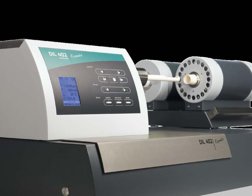
Advantages using NanoEye

Perfect Linearity
compared to conventional transducer systems – for measurements with large thermal expansion and
unmatched linearity.

Wider Measuring Range Than Ever Before
up to a factor of 10 compared to traditional dilatometers – for measurements on a large variety of different
sample lengths with different thermal expansion behavior without manual adaption of measuring range.

Friction-Free Construction
without sliding or rolling friction and stick-slip effects – for highest reproducibility of results.

Displacement Determination with Sub-Micrometer Resolution
over the entire measuring range – for detecting even the smallest effects at every temperature.

Controlled Contact Force During the Entire Measurement
for measurements on small, delicate, fragile or foamed samples without risk of non-reproducible
deformation.

Extremely Small Forces
adjustable for measurements on green bodies or soft samples.

Maintenance-Free

                                                                                                               7
Two versions of the DIL 402 Expedis are specially designed for both
                research & development and sophisticated industrial applications:
                The comprehensive, fully-equipped Supreme model and the upgradable
                Select type (for a detailed comparison between the two models see
                page 21).

Designed to Master the Challenges of the Future

                Optimum Adaptability                 High Sample Throughput
                One or two furnaces, manual or       The combination between the
                motorized furnace operation,         double furnace design and a dual
                single or dual sample holders,       sample holder used in dual mode
                tube type or rod type sample         increases the number of possible
                holders … these are only some of     measurements tremendously and
                the features the Expedis Select or   boosts the instrument’s efficiency.
                Supreme provide to match nearly
                all application scenarios.

8
Greatest Variability in            Widest Temperature Range
Contact Force                      from -180°C to 2000°C
The DIL 402 Expedis series is      To cover this temperature
the first horizontal dilatometer   range, different furnaces are
series on the market which         available and can be used
allows for force modulation        both in the single furnace and
and, by this means, bridges the    double furnace format.
gap between dilatometry and
thermomechanical analysis
under oscillatory load.

For test runs under static
force conditions, different            Furnace Type/Heating Element         Temperature Range
contact forces can be selected.
Therefore, both models are                                      Copper      -180°C … 500°C
ideally suited to measure not                            Stainless Steel    -150°C … 1000°C
only soft samples but also
rigid, fragile materials.                             Fused Silica (SiO2)   RT … 1150°C
                                                   Silicon Carbide (SiC)    RT … 1600°C
                                                               Graphite     RT … 2000°C

                                                                                                9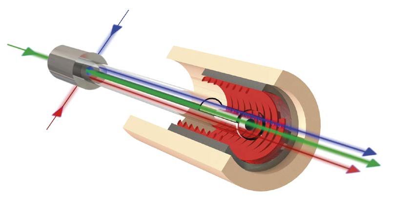
Smart Usability
 Means More Than
 Just “Easy to Use“

 Automatic Sample Length                 Large Measurement Range               Perfect Temperature Stability
 Detection                               with Constant Resolution              of the Measuring System

 Measuring the sample length with        In the past, it was often necessary   Thanks to the elaborate electrical
 a caliper runs the risk of result       to adapt the measuring range          temperature control of the
 scatter, especially for soft samples.   to the expected expansion or          NanoEye, the measurement signal
 The DIL 402 Expedis is capable of       shrinkage of the sample to avoid      is not affected by environmental
 detecting the initial length of a       signal overflow. With the new DIL     temperature fluctuations.
 sample automatically prior to the       402 Expedis, this is no longer the
 start of a test run under condi-        case. There is just one measuring
 tions identical to those during the     range which is wide enough to
 measurement itself.                     quantify even the largest dimen-
                                         sional changes with a constant
                                         high resolution .

10
Temperature Measurement
at the Right Spot
In order to conveniently measure
various sample lengths , the
thermocouple is adjustable. A
guiding rod accommodates the
thermocouple to place it in the
desired position without bending.
MultiTouch
A stable position of the sample inside
the sample holder is a deciding factor
for successful measurement results.
The MultiTouch feature places the
sample into the optimum position
using a unique, tail-like motion.
11Outstanding Conditions
for Pure Atmospheres
Separate Gas Paths for Protective and Purge Gases
When using the three mass flow controllers (MFC, optional), the gas flow
paths inside the instrument are split: the protective gas first passes through
the measuring cell and then enters the sample chamber, whereas the purge
gas(es) are directly fed into the sample chamber. All protective and purge
gases leave the instrument together via the furnace exhaust. In the standard
version, if only one MFC is integrated, the gas takes the same path as the
protective gas mentioned above.
Purge Gas 2
Protective Gas
Purge Gas 1
Schematic of the gas paths inside the instrument when using
one protective gas and two purge gases
12Silicon-Carbide Furnace with transfer line connected for evolved gas analysis
Vacuum-tight Design for Oxygen-Free Measurement Identifying by
Best Sample Conditions for Investigating Metals and Evolved Gas Analysis
Alloys
The instrument can be equipped During the test run, in order to The vacuum-tight design of the DIL
with evacuation systems such as keep the residual oxygen concen- 402 Expedis is ideally suited for
AutoVac for fast evacuating and tration at the lowest possible level, connection to a QMS or to an FT-IR
gas-refilling as well as measure- the OTS® (Oxygen Trap System) via capillary coupling to the SiC
ments under vacuum. can be applied. A getter ring on a furnace. Outgassing of impurities,
ceramic substrate is mounted in additives, organic binders and/or
the sample carrier tube and traps decomposition products can thus
all oxygen residue within the inert be studied.
purge gas.
13Proteus® Software
Best Practice for Measurement and Evaluation
The unique Proteus® 7 dilatometer software offers everything a user could Density Determination
ever want and need: It runs smoothly, provides reliable results, and it is fast
and efficient. It provides a large range of functions, but – at the same time This program add-on allows
– offers a clearly-arranged user interface. Additionally, it is intuitive and determination of the density
thus easy to learn. change of samples with varying
consistency, i.e., solids, viscous
But … that’s not all. There are some more options inside which impress materials such as pastes, liquids or
even the most experienced operators – particularly the Density Determi- melts as well as the volumetric
nation, the patented c-DTA® and the new, innovative Identify software expansion of isotropic materials.
features. (More about Identify on pages 16/17).
Patented* c-DTA®
The c-DTA® signal gives the
opportunity for simultaneous
analysis of length changes and
endothermal/exothermal effects.
It can also be used for temperature
calibration.
* DE102013100686
14Special Features of the Proteus® Software for
DIL 402 Expedis Select and Supreme at a Glance*
Software-controlled force adjustment
(incl. constant forces, ramps, steps)
Force modulation
Density Determination
c-DTA® for temperature calibration or determination of
caloric effects
RCS Rate-Controlled Sintering
Identify identification of unknown ΔL/L0 curves through
database comparison
Advanced Software
(for extended evaluation of the measuring data)*
Thermokinetics
PeakSeparation (for processing the 1st derivative)
* for information which software features are included as standard
and which ones are optionally available, please see page 21
15Identify
Built-In Thermal Analysis Expertise
The unparalleled Identify, for the identification and interpretation of DIL measurements includes
several NETZSCH libraries with hundreds of entries from the ceramic, inorganic, metal, alloy, and
polymer or organic fields. Additionally, user-specific libraries can be created. They can be shared
with other users within a computer network.
Identify allows the identification of unknown samples from the absolute values, the slope or the
shape of a measured curve. This will also open up the opportunity to compare known samples
against a variety of other samples, enabling one to make a statement about material quality.
Finally, all measurements can be stored in the extensive database and are always available for
identification or quality comparison.
16Identify provides all information with one single click
Identification
of unknown measurement curves
Quality Control
via agreement between the current measurement
and selected database entries
Archiving functionality
for present measurements and existing
database entries
17Applications
Thermal Behavior of Carbon Fiber-Reinforced Carbon up to 2000°C
Photo: SpaceX
Comparison of two expansion measurements of a C/C material, measured 45° (black)
and 0° (red) relative to the fiber direction; heating rate: 5 K/min, He atmosphere, constant
contact force: 225 mN, graphite sample holder. Displayed are the relative length changes
(solid lines) and the mean coefficients of thermal expansion (m. CTE) based on 20°C
(dashed lines).
Bild: SpaceX
This composite material is At 2000°C, the relative length
composed of a matrix of pure change (dL/L0 in %) as well as the
carbon to which carbon fibers are corresponding mean CTE of the
added. It exhibits high mechanical specimen cut out with a 45° angle
strength associated with high relative to the fiber direction
temperature stability. Originally (black) are just about 7% higher
used in aerospace engineering, it is (0.155% and 0.781 x 10⁻⁶ 1/K)
nowadays also applied in furnace than that of the sample cut out
and equipment manufacturing, with a 0° angle (red, 0.144% and
hollow glass or the semiconductor 0.727 x 10⁻⁶ 1/K). This suggests a
industry. quite low dependency of the
material properties within these
The thermal expansion of C/C spatial directions.
materials depend on their fiber
architecture. In the present case,
experiments with angles of 45°
(black) and 0° (red) relative to the
fiber orientation were conducted.
Both curves depict a characteristic
behavior of such fiber-reinforced
composites: passing a length
change minimum between
approx. 300°C and 400°C
followed by expansion.
18Volumetric Expansion of an Aluminum Alloy into the Melt
The behavior of an aluminum- While the volume increases, the
based alloy during heating is initial density drops down for
illustrated here. Displayed are the about 10% (from 2.66 g/cm3 to
volumetric expansion (dV/V0, 2.40 g/cm3) until the end of the
black) and the density change measurement.
(red) which can both be calculated
from the measured thermal The c-DTA® curve (blue) clearly
expansion data by using the shows the melting range by
NETZSCH Density Determination endothermal effects.
software.
After an initial linear expansion,
the aluminum alloy starts to melt
at 559°C (extrapolated onset
temperature of the c-DTA® signal dV/Vo/% Density/(g/cm3) c-DTA®/K
in dashed blue). For realizing such Density:
↓ exo 2.70
10
an experiment, a special container 12 2.66 g/cm3
(here alumina, see photo) is 621.8 °C 2.65 8
necessary. 10
6
2.60
During melting, a strong
8
expansion occurs representing the 4
mushy region in which liquid and 2.55
2
solid state are present together. 6
559.0 °C
Above 622°C, the entire sample is 2.50 0
molten. 4
-2
2.45
2 -4
2.40
2.40 g/cm3
-6
0
100 200 300 400 500 600 700
Temperature/°C
Thermal behavior of an aluminum-based alloy, heating rate: 5 K/min, He atmosphere,
constant contact force: 250 mN, alumina sample holder, alumina container. Displayed
are the volumetric expansion (black solid line), the curve of the calculated density
change (red solid line) as well as the c-DTA® curve (blue dashed line).
19Applications
Without Oxidation to the
Highest Temperatures!
Tungsten is a metal very sensitive dL/Lo /%
to oxidation. But due to the
vacuum-tight design of the
m. CTE(20.0 ... 1500.0°C)
Expedis Supreme, the material can 0.8 5.143E-06 1/K
be measured in pure He atmos-
phere (in combination with OTS®
– Oxygen Trap System) to get its 0.6
true expansion behavior. There is
no need of reducing atmosphere 0.4
m. CTE(20.0 ... 1500.0°C)
to suppress superficial oxidation Measurement 5.129E-06 1/K
(which would change the color of
the sample). 0.2
Comparison of Measurement 0.0 Theoretical data
and Literature
200 400 600 800 1000 1200 1400 1600
measured CTE Temperature /°C
between 20°C and 1500°C
5.143 x 10⁻⁶ 1/K Thermal behavior of tungsten, sample length: 25.00 mm, heating rate: 5 K/min, He
atmosphere, constant contact force: 250 mN, alumina sample holder. Displayed are
Literature values the length change of the sample (black solid line) together with the tabulated theore-
(NIST standard table) tical data (red dashed line, NIST standard table).
5.129 x 10⁻⁶ 1/K
Difference between Tungsten sample
measurement and literature
1.4 x 10⁻⁸ 1/K
OTS® (Oxygen Trap System)
The picture on the left site illustrates two tungston samples after the experiment.
The used tungsten samples were measured up to 1640° C. The right sample is corroded
because of non-oxygen free atmosphere during measurement. The left sample,
also shown in the picture above, is still shiny due to a measurement in oxygen free
atmosphere.
20Configurations
Feature Supreme Select
Temperature range -180°C … 2000°C -180°C … 1600°C
Measuring range 50 mm (± 25 000 µm) 20 mm (± 10 000 µm)
Δl Resolution (over entire measuring range) 0.1 nm 1 nm
Double furnace sliding carrier
Motorized furnace operation
Vacuum-tight design
Automatic Evacuation System – AutoVac
Mass Flow Controller (MFC) – single/triple / /
Available Cooling Devices Vortex, LN2 Vortex, LN2
Electrical temperature control of the measuring cell
Force change (ramp, step at each new segment)
Force modulation
Single/double DIL / /
Automatic sample length detection
Softening Point detection
Density Determination
c-DTA®
RCS (Rate-Controlled Sintering)
Identify
Evolved gas analysis (coupling with GC-MS/QMS
and/or FT-IR) – for SiC furnace
Both instrument models work on the basis of DIN 51045, ASTM E228, ASTM D696 or DIN EN 821.
Included in standard configuration
Optional
21Key Technical Data
Key Technical Data – DIL 402 Expedis Supreme and Select
Design Pushrod dilatometer, as single or as dual system
Different types, interchangeable: Steel, copper, SiO2,
Furnaces
SiC, graphite (details see on page 9)
Depending on furnace type:
Heating rates ··
Steel, copper, fused silica, silicon carbide -
0.001 ... 50 K/min
··
Graphite - 0.001 … 100 K/min
Cooling systems Vortex, liquid nitrogen, air compressor (SiC furnace)
SiO2, Al2O3, graphite, user exchangeable
All sample holders are available as
Sample holder systems ··single systems
··dual/differential systems
SiO2 and Al2O3 sample holders can be purchased as tube or rod design
Expansion and penetration mode:
Initial length: 0 to 52 mm (0 to 25 mm for 2000°C graphite furnace)
Sample dimensions
Diameter (single): 12 mm standard, optional 19 mm
Diameter (dual): 8 mm
Displacement system NanoEye
Temperature accuracy 1K
Temperature precision 0.1 K
Temperature resolution 0.001 K
Thermal stability (isothermal) ± 0.02 K
Displacement method (by using metal references and protective disks)
Temperature calibration
or via c-DTA®
± 10000 µm (Select)
Measuring Range
± 25000 µm (Supreme)
1 nm/digit (Select)
Resolution
0.1 nm/digit (Supreme)
Accuracy 0.003%, inter alia, dependent on the sample length
Repeatability 0,002 %, inter alia, dependent on the sample length
Force Range (load at sample) 10 mN ... 3 N, in steps of 0.2 mN
Force resolution 0.001 mN
Gas atmosphere Inert, oxidizing, reducing, vacuum
MFC
Gas control ··
Standard: 1 x protective gas
··
Optional: 1 x protective gas, 2 x purge gas
Oxygen Trap System (OTS®) Optional, for single and for dual sample holder systems
Windows 7 32/64 bit Professional®, Windows 7 32/64 bit Enterprise®,
Software
Windows 7 32/64 bit Ultimate®, Windows 8.1 Pro® and Enterprise®
22Expertise in Service
All over the world, the name NETZSCH stands for comprehensive ∙∙∙∙ Installation and commissioning
∙∙∙∙
support and expert, reliable service, before and after sale. Our qualified Training
personnel from the technical service and application departments are Hotline service
∙∙∙∙
always available for consultation. Preventive maintenance
Individual maintenance services
∙∙∙∙
In special training programs tailored for you and your employees, you Calibration service
will learn to tap the full potential of your instrument. To maintain and IQ / OQ
protect your investment, you will be accompanied by our experienced On-site repairs with emergency
∙∙∙∙
service team over the entire life span of your instrument. service for NETZSCH components
PC supported diagnostics
∙∙∙∙
The NETZSCH applications laboratories are a proficient partner for E-mail reporting
nearly any Thermal Analysis issue. You will receive high-precision Moving / exchange service
∙∙∙∙
measurement results and valuable interpretations from us in the Technical information service
shortest possible time. This will enable you to precisely characterize Spare parts assistance
∙∙∙∙
new materials and components before actual installation, minimize Accessories catalogue
risks of failure, and gain decisive advantages over your competitors. For Software update service
∙∙
production problems, we can work with you to analyze concerns and Application support
develop solutions. Environmental instrument recycling
23The NETZSCH Group is a mid-sized, family-owned German company
engaging in the manufacture of machinery and instrumentation with
worldwide production, sales, and service branches.
The three Business Units – Analyzing & Testing, Grinding & Dispersing and
Pumps & Systems – provide tailored solutions for highest-level needs. Over
3,000 employees at 210 sales and production centers in 35 countries across
the globe guarantee that expert service is never far from our customers.
When it comes to Thermal Analysis, Calorimetry (adiabatic & reaction) and
the determination of Thermophysical Properties, NETZSCH has it covered.
Our 50 years of applications experience, broad state-of-the-art product line
and comprehensive service offerings ensure that our solutions will not only
meet your every requirement but also exceed your every expectation.
NGB · Dilatometer Series DIL 402 Expedis Select and Supreme · EN · 0915 · NWS · Technical specifications are subject to change.
NETZSCH-Gerätebau GmbH
Wittelsbacherstraße 42
95100 Selb
Germany
Tel.: +49 9287 881-0
Fax: +49 9287 881 505
at@netzsch.comYou can also read